I have a newbie electronics question.
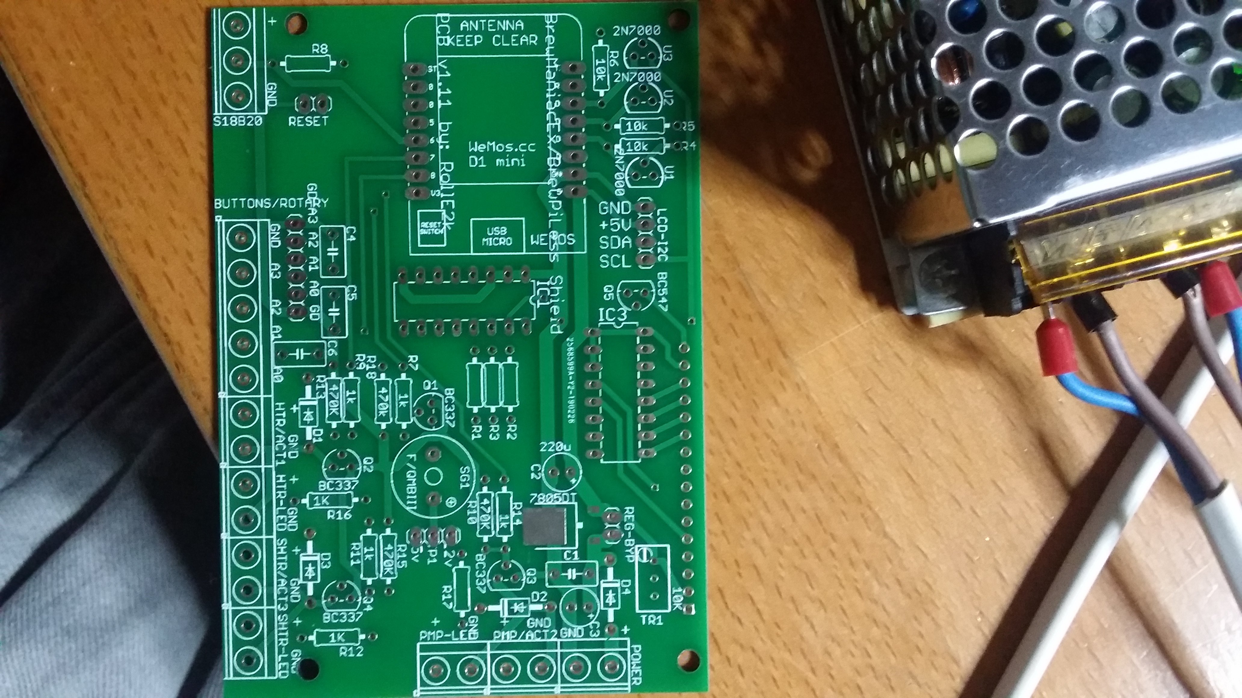
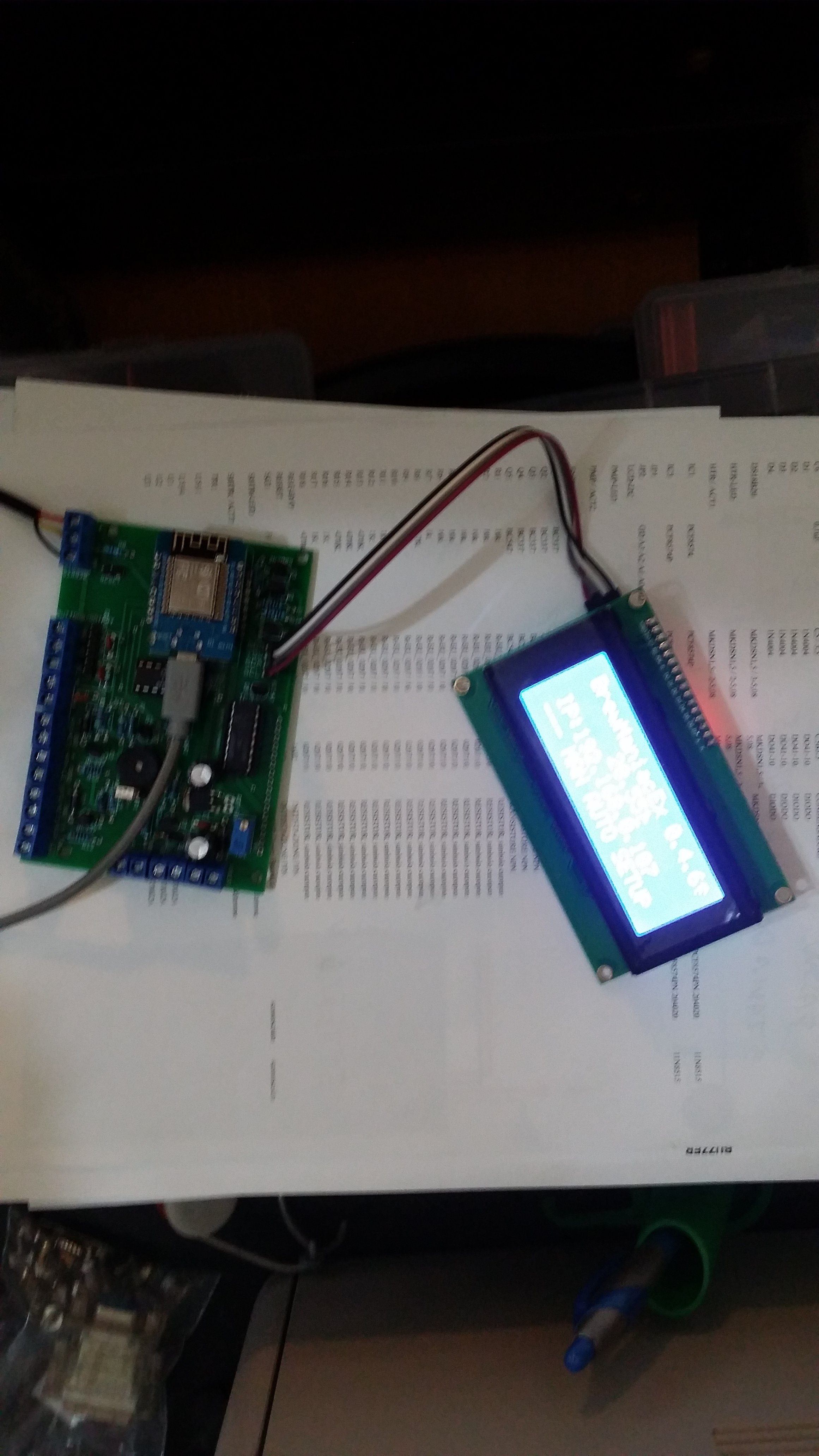
I have wired up a BrewManiac on my breadboard, and in an attempt to keep it as simple as possible, I have mixed 3v3 and 5v to the components.
Instead of using level shifters, I feed the PCF8574P with 3v3 on Vdd, the LCD is getting 5v on Vcc, but get SCL and SDA directly from the D1 mini. The relay module is getting 5v on JDvcc and 3v3 on Vcc, and is contolled directly by the D1 mini from D5.
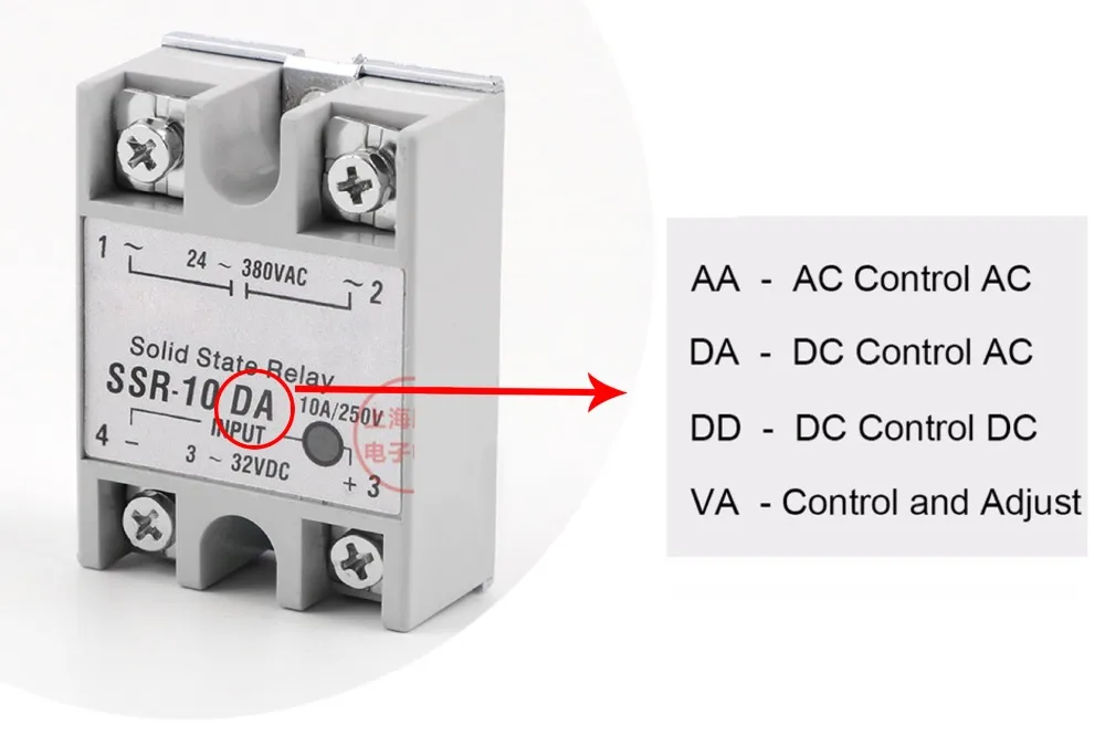
I plan on controlling the SSRs for the heaters with 3v3, directly from the D1 mini as the SSRs have 3-24v input range.
All of this is working fine on my breadboard (well, I havent connected the SSRs yet, since they are of Zero Crossing DA type, I need some 230VAC connected so I can actually see that it works. I need to clear my workbench for that, so it may take some time
")
)
First question is if I'm doing something stupid, if we imagine that the D1 mini has unlimited current. Will anything break in the long run, because I mix voltages like I do, or is it OK to do?
Second question is if the SSRs and the rest of the components will pull more current than the D1 mini can deliver? I have searched a bit on the net, and it seems the GPIOs can deliver 12 mA each, and the SSRs are specified to pull 13 mA@12V. Can I then assume the SSRs will pull 3,6 mA@3v3? (I did the U=R*I math). If this is correct, I guess I should be able to control the SSRs without any transistors between the pins and the SSR?
Or, is this bad practice and should not be done in "production" even if it works on my experiment breadboard?


![Craft A Brew - Safale S-04 Dry Yeast - Fermentis - English Ale Dry Yeast - For English and American Ales and Hard Apple Ciders - Ingredients for Home Brewing - Beer Making Supplies - [1 Pack]](https://m.media-amazon.com/images/I/41fVGNh6JfL._SL500_.jpg)