• Please visit and share your knowledge at our sister communities:
  • If you have not, please join our official Homebrewing Facebook Group!

    Homebrewing Facebook Group

Pressuremon, DIY pressure monitor for kegs

Homebrew Talk

Help Support Homebrew Talk:

This site may earn a commission from merchant affiliate links, including eBay, Amazon, and others.
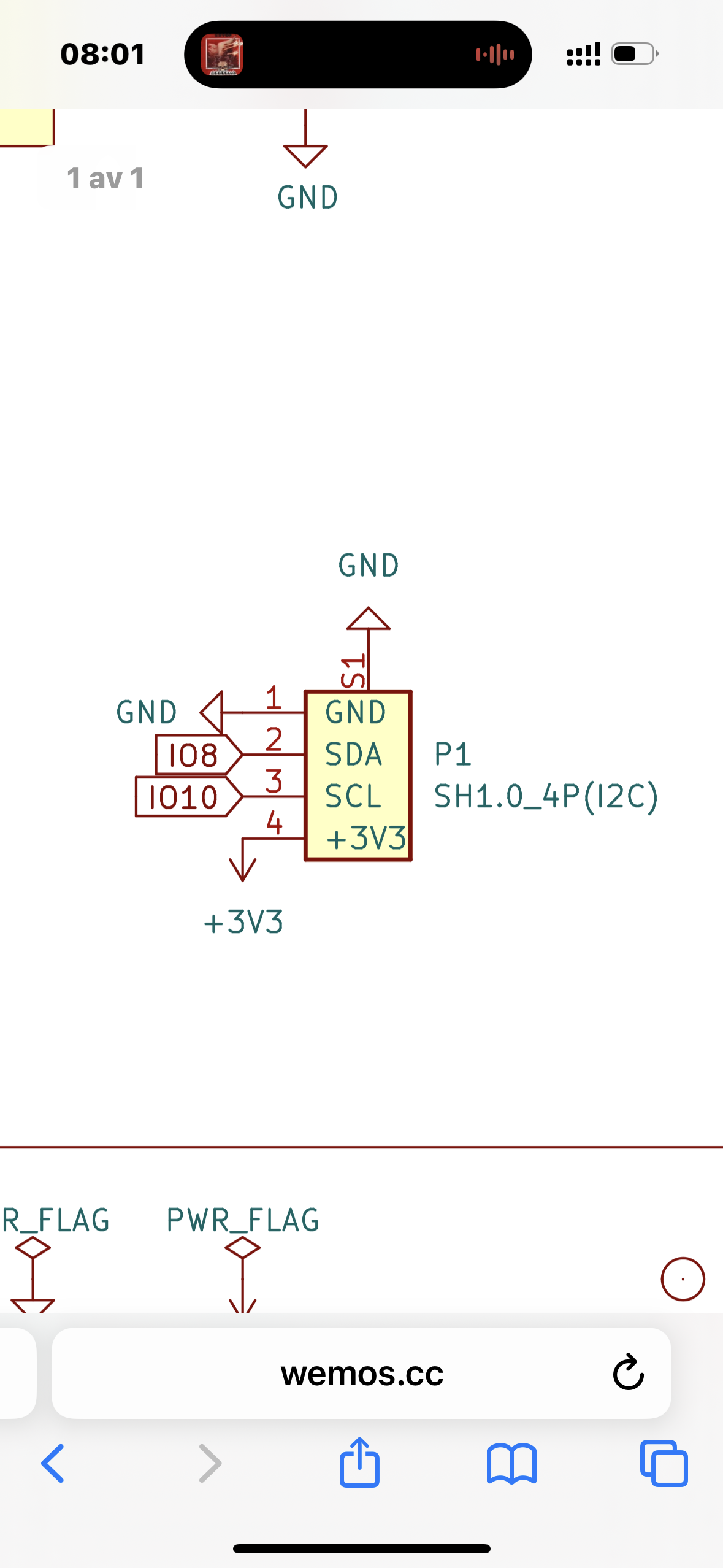
on I2C devices the power supply is not transferred to the data and clock lines as these are open drain so they only switch low and need to be pulled high via a pullup resistor, some modules have these on board so if you wish to use 5V they should be removed and replaced with resistors to the 3V3 supply, to be sure just check the resistance between supply and signal wire.
 
A few words of caution for any new builders.

I never managed to get the ADC and analogue pressure sensor to work.

So when the I2C sensor arrived I thought I was all good to go.

I had also bought the 1mm spaced connector to wire onto the pressure sensor straight into the I2C socket top left of board.

BEWARE this circuit pin diagram below is WRONG

Pico wiring.png


GND is wired into the Left
3.3 V is on the far right.

SDA is next to ground
SCL is next to 3.3V


If you wire your sensor up as per the circuit diagram you'll cook the PICO as I found out and also @nzm who kindly has helped me sort this out.

Is it very difficult to get a 1.3 OLED as opposed to a 0.96 OLED working on the pressuremon? I would be keeping my pressuremon powered all the time, or powered on periodically when I'm in the bar area.
 
A few words of caution for any new builders.

I never managed to get the ADC and analogue pressure sensor to work.

So when the I2C sensor arrived I thought I was all good to go.

I had also bought the 1mm spaced connector to wire onto the pressure sensor straight into the I2C socket top left of board.

BEWARE this circuit pin diagram below is WRONG

View attachment 883760


GND is wired into the Left
3.3 V is on the far right.

SDA is next to ground
SCL is next to 3.3V


If you wire your sensor up as per the circuit diagram you'll cook the PICO as I found out and also @nzm who kindly has helped me sort this out.

Is it very difficult to get a 1.3 OLED as opposed to a 0.96 OLED working on the pressuremon? I would be keeping my pressuremon powered all the time, or powered on periodically when I'm in the bar area.
The pinout in the official schematic is correct.

Adc is still work in progress and with the current design you will need a 3.3v sensor. 5v is not tested and would require a new design with voltage divider that would decrease the accuracy further.

I would recommend the i2c sensor.

Using the i2c will work if you power it always, if you run it on battery it will drain that quickly
 

Attachments

  • IMG_1137.png
    IMG_1137.png
    742.3 KB
I've changed to the I2C sensor.

I'm not sure if you mean the schematic I showed or as on your attachment.

But if you wire the I2C plug the way it appears on the mischianti.org it is wrong and you will cook the pico.

Never managing to get the adc and analogue working was an overstatement, it record a reading but was unable to send further readings.
I will use the analogue sensor on my Brewpiless pressure spunding setup which is what I bought it for so no loss at all other than a learning experience.
The schematic is from wemos homepsge and shows the correct pins for the connector. I would not trust any 3rd party documentation.

I have only tested the adc with a xidebei analog sensor of 3.3v so as i stated that option is experimental.

What was the sensor you used?
 
The schematic is from wemos homepsge and shows the correct pins for the connector. I would not trust any 3rd party documentation.

I have only tested the adc with a xidebei analog sensor of 3.3v so as i stated that option is experimental.

What was the sensor you used?
I'll have a look at the analogue sensor when I get home.
I do remember it was 5 to 12V rated.
I used 5V on a separate circuit for supply.
 
Back
Top