YABC-Yet a Brew Controller: BrewManiacEx

Homebrew Talk - Beer, Wine, Mead, & Cider Brewing Discussion Forum

Help Support Homebrew Talk - Beer, Wine, Mead, & Cider Brewing Discussion Forum:

This site may earn a commission from merchant affiliate links, including eBay, Amazon, and others.
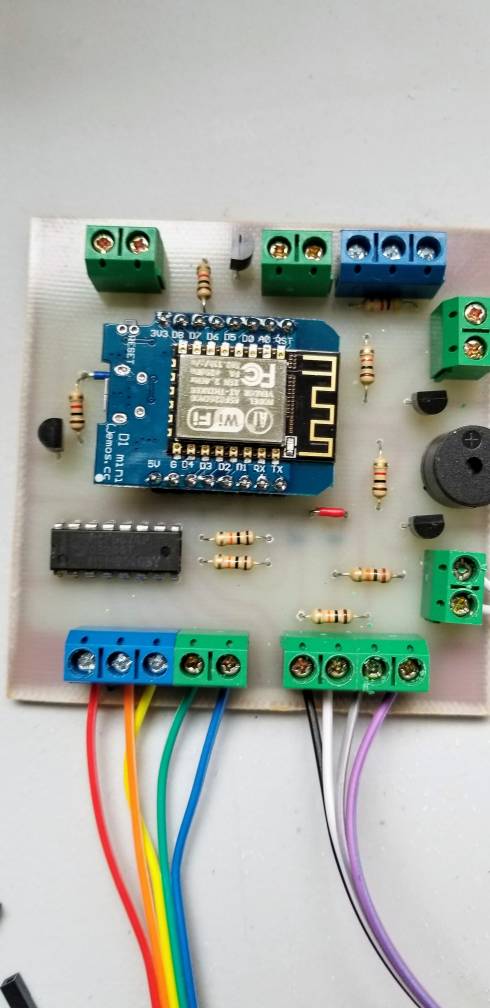
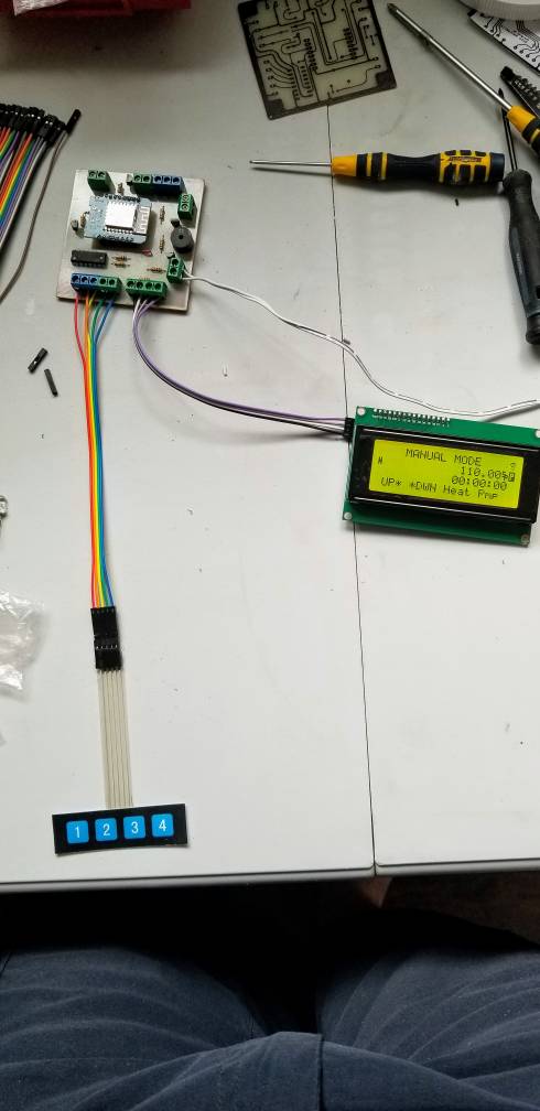
Just an update, I am finally working on the toner transfer PCB I designed to test if it works. I did the transfer the other day and I just gave it a bath in ferric chloride. I will drill holes and go nuts soldering the parts this weekend. If everything works I will release the .BMP of the printable circuit board and the component silkscreen orientations for the other side. this is a single sided board that should be fairly doable for the average DIYer.
 

Attachments

  • 20180918_181651.jpg
    20180918_181651.jpg
    384.5 KB · Views: 247
  • 20180918_181658.jpg
    20180918_181658.jpg
    437.9 KB · Views: 245
  • 20180918_183155.jpg
    20180918_183155.jpg
    448.4 KB · Views: 266
Is there any advantage on making a fully functional PCB with transistors driving the outputs vs connecting multiple modules and stuff to MCU outputs?

I find doing it the sound way much compact and simpler, than otherwise welding many different components..
 
Hi fellows
Solder Dallas temp sensor directly to NodeMCU D6, +3.3v, GND, Pull-up 4K7R from 3.3V to D6 but the software do not detect it. Any ide why not?
 
Is there any advantage on making a fully functional PCB with transistors driving the outputs vs connecting multiple modules and stuff to MCU outputs?

I find doing it the sound way much compact and simpler, than otherwise welding many different components..

The output of ESP8266 is 3v3 level. If the SSR/Relay you choose need higher driving voltage, you are out of luck. Also, the maximum current is around 150mA, you will need to make sure the SSR/Relay won't need more to drive.
By using the transistor, the limit is on the power supply.
BTW, ESP8266 is said to be 5v tolerant, which accepts 5v signal.
 
Is it possible to scan an initialize sensor(s) without display and knots. And a hint for getting OLED support, if possible
 
Is it possible to scan an initialize sensor(s) without display and knots. And a hint for getting OLED support, if possible

All my OLED lcds are broken, so I didn't apply latest change to OLED option for not being able to verify. It can be done, though.

With latest LCD mirror display on web page, you can scan the sensors on browsers.
 
With latest LCD mirror display on web page, you can scan the sensors on browsers.

That was good news! I tryed, in the doc, to find how to scan the sensors but could not find it. Could someone give me a hint how to scan for sensors. Maybe there is a setup page i missed since I also is unable to find the start of autothune PID.. Ed. Found it!
 
Last edited:
Last edited:
If there is enough interest I will order a batch of boards from DirtCheap PCB of this board https://www.homebrewtalk.com/forum/...oller-brewmaniacex.596907/page-2#post-7903360
I need to sell at least 5 boards to start order.
Boards are Five dollars a piece and include shipping to the USA
I have to check postal rates for International shipping.
I will provide a board to both Pocketman and Rolle2k

I am intrested if it`s possible for you to send it to Norway? I can buy 2 if that helps, or even 3 - heck I even throw in the same US for pocketmon as the boards cost.
 
I am intrested if it`s possible for you to send it to Norway? I can buy 2 if that helps, or even 3 - heck I even throw in the same US for pocketmon as the boards cost.
I sent a few boards on another project to Norway a while back w/o out a problem.If you order 3 boards I'll send in the order. You can even pick the color of the solder mask
 
I sent a few boards on another project to Norway a while back w/o out a problem.If you order 3 boards I'll send in the order. You can even pick the color of the solder mask
Do they come with everything soldered on?
Or is it just the PCB?
 
I will provide a board to both Pocketman and Rolle2k

No need to provide me with board, i already have 7pcs laying around, i'm just happy somebody is using the board :)
Let me know if you wonder anything about components and/or building the boards, since there are a few different setup possibilities.
 
No need to provide me with board, i already have 7pcs laying around, i'm just happy somebody is using the board :)
Let me know if you wonder anything about components and/or building the boards, since there are a few different setup possibilities.
The 7805dt power reg.. is that through hole or surface mount?
EDIT: I figured it out
 
Last edited:
The 7805dt power reg.. is that through hole or surface mount?

Surface mounted. It's the only part that is surface mounted on the whole board. For cooling purpose, and I think most people can solder such a chip even if you are not used to smd soldering.

I tried make the board as much through hole as possible, so everybody can solder this themselves. If I did it only for myself, smd would have been good.
And for those not used to smd soldering, just tin the large pad first, then put the regulator there with tweezers, while still keeping the pad hot.
 
I like your design. Is it still current? If so, it's kind of buried in this thread.

As far as I know nothing have changed output wise since i made the board, and if it would i could always update the design. I tried make it quite universal but still have compact footprint.
Let me know if you try it out, myself I run it both for BrewmaniacEX and BrewPiLess.
 
As far as I know nothing have changed output wise since i made the board, and if it would i could always update the design. I tried make it quite universal but still have compact footprint.
Let me know if you try it out, myself I run it both for BrewmaniacEX and BrewPiLess.
I would like to see an SMD version and a smaller footprint.
 
As far as I know nothing have changed output wise since i made the board, and if it would i could always update the design. I tried make it quite universal but still have compact footprint.
Let me know if you try it out, myself I run it both for BrewmaniacEX and BrewPiLess.
That's great. Just ordered 10 PCBs from JLCPCB for less than $13AUD ($9.02US) with postage. I have no need for that many boards but they only charge $2US for the PCBs and the rest of the cost is postage.
 
Last edited:
I would like to see an SMD version and a smaller footprint.

Sorry to say, but i won't be making SMD version. It wouldn't really be much smaller either, since transistors still need to be larger for possible dissipation. A change of connection terminals to some smaller ones, that would make a bigger difference.
But why would you need smaller board? Best way to use this one is to piggyback behind the LCD, and it is really not much bigger than the LCD-board itself. The shield/board is 70x100mm, and 20x4 LCD's are approx 60x98mm.
 
My ex-neighbor (I’ve moved out) is a freelancer hardware engineer. He has all necessary equipment to design a PCB and solder all required SMD components. But he will not do it for free. So the question is – how much you are willing to pay for such a board and how many boards can be sold?
 
My ex-neighbor (I’ve moved out) is a freelancer hardware engineer. He has all necessary equipment to design a PCB and solder all required SMD components. But he will not do it for free. So the question is – how much you are willing to pay for such a board and how many boards can be sold?
I'm fine with the board as is. SMD soldering is not all that hard to do if you have the correct materials- the biggest being paste solder and flux. Tons of instructional videos out there on YouTube. I can't design the PCB yet and I'm always appreciative of people like RollE2k that have that ability and share with us.
 
froot: They are all connected to what they should...
R10/R13 is between ground (red thick trace) and the base of the corresponding transistors (Q3/Q2)..
C6 is between A0 button and ground... and these small caps is not needed for buttons, but for rotary encoder.
I added the caps, because this board is possible to use with pocketmon's brewpi-style fermenter controller also..

It would be possible to make everything more compact if going for surface mounted stuff, but i like to make this as DIY-friendly as possible - and also, space is not an issue when you mount it behind the display, because it's kind of the same size. And you still have output pins for off-board display mount.

I'll let you know how it works when i have finished a first board..
Hey RollE2k. There's not a lot of chatter about your board or this project. In regards to the rotary encoder, how does it interact with the LCD menu system? Did you make any changes to the code to make it work?
 
Hey RollE2k. There's not a lot of chatter about your board or this project. In regards to the rotary encoder, how does it interact with the LCD menu system? Did you make any changes to the code to make it work?

I have nothing to do with the code, that is Vito (pocketmon). As far as i know, it is not possible to use rotary with BrewManiacEx, but it is with BrewPiLess (which is possible to run with the same board)
I only made the board as to the output specifications, because i wanted a piggyback board to use myself.
Then when i started designing i tried to make it a bit more universal, and shared it so that other people shouldn't have to put down time making a design themselves.
It's kind of an updated and alot better "open ardbir" which you probably can find more users running.
 
I have built an 'open ardbir' and love it's functions but wished it had more funtionality. I stumbled across brewmaniacex when I googled 'open ardbir esp8266'. The documentation from pocketmon is great but I have only seen a couple of hints about the rotary encoder. I have ordered your PCB and parts and wasn't sure if I should stick with buttons or use a rotary encoder. I'll obviously stick with buttons.

On a seperate note regarding the IO expander. I had trouble finding the PCF8574 IC but found PCF8574P on Aliexpress (Australian suppliers had other options). Couldn't confirm whether the 2 ICs were identical as the data sheets weren't crystal clear. I am assuming it is the same I2C address but will change if it doesn't work?
 
pbezza: the PCF8574P is correct, i think the P is only for packageing which is DIP16. there is also a PCF8574A (or PCF8574AP) which does have alternative i2c adress, so if using that one one may have to edit the adress in the code before flashing. I found out this the hard way, because i'm a hardware guy, with pretty much no knowledge of coding at all.
The PCF8574-chip for piggyback display should work if it's either PCF8574P or PCF8574AP, because the code in default configuration automaticly scans for that adress.

If you already use Open Ardbir, you will instantly find this an upgrade. Both possible to change settings and such with computer/phone/pad, but also the menu is better and the system is alot more responsive. Also there is better resolution with temperature and such. And i like that it is possible to use up to 5 different temperature sensors at the same time.
 
Sounds like I'll enjoy this project. I ordered 10 PCF8574P ICs from Aliexpress and plan on using 2 of them on your board. I have a whole new suite of brew gear being put together out of the cheapest parts I could find (WAF Budget). New gear gives me a a volume upgrade from 30L to 58L urn and a reconfigure of the mash recirculation system. Old pot can be used as a HLT. Should work with 'open ardbir' nicely until I receive and populate one of your PCBs. Cheers for the design/files which made it real simple to upload and purchase from JLCPCB.
 
Ciao ragazzi, sto scrivendo dall'Italia per il progetto, sarei interessato anche io al progetto
 
Last edited:
I am intrested if it`s possible for you to send it to Norway? I can buy 2 if that helps, or even 3 - heck I even throw in the same US for pocketmon as the boards cost.

I'm interested in getting a board.........
The boards arrived today and I will ship them out on Monday check your PM for more info. I still have more boards available if anybody else is interested.
 
Back
Top