simple control panel

Homebrew Talk - Beer, Wine, Mead, & Cider Brewing Discussion Forum

Help Support Homebrew Talk - Beer, Wine, Mead, & Cider Brewing Discussion Forum:

This site may earn a commission from merchant affiliate links, including eBay, Amazon, and others.
back to the OP, why not go biab? you can get many of the benefits, easier to justify cost, and do it for 1/3 the price or so of a 3 pot system. it's approximate obviously

That's what I would do if on a budget but wanting some control elements.
 
bad news: I only am planning on one pump. I fly sparge now, because I have two coolers (one sparged into the other while I heat my pot). I am thinking of trying Bobby's NMODBS method, in which case I would switch the connections for the pump. Everything will be camlock, so it won't be that inconvenient.

knub: I thought about BIAB, but since I'm used to a 3 stage system, I'm comfortable that way, plus I haven't experimented with BIAB enough to fully commit to it. Although, I am sewing a bag for my mash tun just to see how that is, even though my manifold works great. Without my manifold I would get EVERY last drop from my tun. And If i went BIAB, I'd definitely need PID controls to monitor the temps as I mash. I've also heard that hoisting grain bags out of kettles doesn't always fare well due to the smaller opening, although I think I cut cut that out. If I did any sort of BIAB, I'd do he Brutus 20 style with two pots. Keggle as mash tun holding grain bag and my 40 qt pot as HLT/BK. Recirculate HLT into MT then at mash out, Pump from MT to HLT/BK. But dammit now you're piquing my interest.
 
understood. what is the current system?

one thought, take a look at this http://www.highgravitybrew.com/productcart/pc/Electric-Kettle-Controller-306p3084.htm

all you need then is to install elements in your kettle, run some cable, voila (assuming you have gfci and all of that in place)

hmm. I''m assuming that knob is a PWM to control the rate of heating, would take some getting used to compared to PID on/off cycles. Interesting though.

Current system is this:
two 36 qt coolers, HLT and MT. HLT has a 90 elbow and valve drains into silicone tube to MT manifold in lid. Manifold on bottom of MT drains via silicone into pot. My pot is the smaller one on the left burner, aluminum 40 qt behind the stainless one. This was a 10 gallon day at my friend's house. We doubled up on burners for water but his keggle handled the whole boil.

thought occurred to me after your last post... Keep my pot as HLT/BK, keep my MT cooler with grain bag (not yet made) and use the manifold on the pot for recirculation of wort for a two vessel system. I'd need a coil in my pot (or use my immersion chiller) but my one pump system (still need to decide on pump) would work that. I figure IF I go into BIAB, might as well go RIMS since I'll have a pump. This way, I only need one element/housing, one outlet (so maybe this time spring for a 220V) and an uber simple CP with one PID for maintaining HLT temp and one button for on/off.

That might be a simple parts list than making a three stage system. My friend is giving me a blank keg, so I was going to make that into my system as well, but that's one more thing to drill into, plus its 15 gallons.

am I missing anything?

View attachment 2013-05-12 14.18.17.jpg
 
mendozer,
i think the big thing is deciding exactly what you want and then lay out a plan. for example, when talking about biab, you wouldn't have it as rims. the two techs are different and if doing biab, you would have a single pot setup. i know there is a lot, but decide exactly what you want and we'll help.

as for what i linked, yes, that is a pwm. what do you mean 'get used to' vs a pid? the pwm will simply function like your stove and you will have to use a thermometer to monitor mash temp and/or boil. a pid you literally set the temp and forget about it. the two techs are very different but have the same result.
 
let me correct myself a little, you could do a rims for biab, but idk why you would. i'd just install an element in the kettle and if you want to recirculate, install a valve in the lid...
 
Hmm I was just going to upgrade my 3 pot setup with a pump, but now all these ideas are making me hesitate about it. I like my setup b/c I hit 70-80% every time. I could use a little more clarification with my beer, sure, but it's still damn good beer. Since RIMS sometimes take a hit with efficiency, maybe I could RIMS, but also batch sparge after to get the last of the sugars out.
 
I still don't understand how you'll fly sparge single-tier with only one pump. You have to move liquid from HLT to MLT, and simultaneously from MLT to BK. That's two pumps if you fly sparge. Batch sparging, sure, 1 pump. I batch sparge, hit 80% every. single. time.
 
I still don't understand how you'll fly sparge single-tier with only one pump. You have to move liquid from HLT to MLT, and simultaneously from MLT to BK. That's two pumps if you fly sparge. Batch sparging, sure, 1 pump. I batch sparge, hit 80% every. single. time.

maybe everything is on a table and just stacked? it seems impossible to me as well.
 
Hmm I was just going to upgrade my 3 pot setup with a pump, but now all these ideas are making me hesitate about it. I like my setup b/c I hit 70-80% every time. I could use a little more clarification with my beer, sure, but it's still damn good beer. Since RIMS sometimes take a hit with efficiency, maybe I could RIMS, but also batch sparge after to get the last of the sugars out.

i had a very similar setup and while i wasn't concerned about efficiency, my problem was consistency. it was the variability from batch to batch that bothered me. if i always hit 60%, at least i can account for it. however, 65% on one and 80% on another was driving me nuts and was a big motivator for me as well.

a 10% range is pretty big and is a decent reason to change your method.
 
I've been hitting 80.0% every time the last several months. I crush my own grain and haven't changed it at all, nor my mash tun. Mash temps, sparge temps, speed of runoff, these things change all the time for me but my efficiency never does. I grind VERY fine and do have some slow runoffs, but I keep doing what I'm doing because of the consistency.
 
yup i have that chart thanks. I'm thinking one BK 3500-4500K with a PWM or PID, whatever ends up being cheaper
 
i had a very similar setup and while i wasn't concerned about efficiency, my problem was consistency. it was the variability from batch to batch that bothered me. if i always hit 60%, at least i can account for it. however, 65% on one and 80% on another was driving me nuts and was a big motivator for me as well.

a 10% range is pretty big and is a decent reason to change your method.
sorry for vague info. I was batch sparging and hitting 77-80% on LHBS grain crush. I switched to fly sparging once I equipped the second cooler with hopes of increased efficiency. I either didn't figure the flow rate right or sparge with enough water (always seemed like too little with 5 gallon batches)
but I was getting 70-75% with erratic results. So for simplicity's sake, I'm going back to batch sparging, possibly Bobby's double sparge method. I'll try that out one batch and see how it goes. As for crush, I've been having the LHBS grind it twice and I'm going to line my MT with a grain bag just to make cleaning and draining easier.
 
Reviving the thread here:

after much thought, I'm sticking with three stage system because I like my batch sparges. I recently received a keg and am receiving another from a friend. Despite the keg's 15 gallon limit, I'll use these for my 5 gallon (and rare 10 gallon batches).
Because now I want two, I'll be using two elements (my current rental has two spare 220 fuses) one on each fuse (30 A fuse?)

I think something like 4500W should be sufficient (about 21 A draw) for each the BK and HLT.

So with this in mind, could the electrically inclined offer a helping hand for making a wiring diagram? What I'll do is make a double outlet box on the wall next to the fuse panel so it can be removed when i leave this place. So for a brew box, I would need two outlets and let's just say we'll use a PID for the hell of it with simple lighted buttons to turn on/off (one button's fine).

I'll mount this box to the frame when I make it.

Untitled.jpg
 
bump. any plans, even simple. never used a PId before. I can figure out setting up the boxes probably connecting basic three wires. Would it be power -> PID -> button?
 
DSC00452.jpg

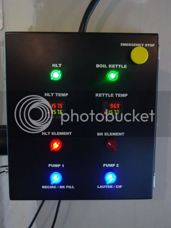
This is almost EXACTLY what I want for a panel, copied the pic from Tiber Brew's build. two elements (Bad news convinced me to go 220) each with a PID and simple on/off switches. I like the emergency kill switch. I don't understand the HLT switch AND the HLT element switch though. Does one act as a failsafe? I'll only have one pump at first, but that simple panel does it all.
And since I'm a noob at this, I have to get this right:
from breaker panel, reserve two 220V slots (30A) and make connections to a "spa panel" which is basically a two outlet box with GFCI features (getting warm?).

Then my control panel, whether wall or brew stand mounted acts as the 220 "middle man" to the spa panel and the keggles in terms of connections.


Also, ebrewsupply has DIY kits for 180 bucks for 2 element kits here
Can the individual parts be had for less? I don't need the 20 or so buttons the kit comes with. All i need (assuming I'm right) are 5 on/off switches assuming I do it just like Tiber's without an extra pump, 2 PIDs, 2 SSRs, one kill switch, and 2 thermocouple hookups.
 
I'm reviving this thread because after days of agonizing over my current propane setup and me wanting to do NG as a stepping stone over to electric (bc it's in my garage) I just said F it after hours of looking at burners and said "I'LL GO ELECTRIC ALREADY!!!!"

I've been fighting it for so long but today I got a nice fat check from Uncle Sam for my tax return and it's going towards this.

I still want to keep it simple though.

to review: 3 stage brewing process (and it's staying that way because I love my little cooler and all it's wonders). I mainly brew 5 gallons, once in a blue moon a 10 gallon.
Equipment has changed a bit:
10 gallon aluminum HLT (soon to be outfitted with sight glass and therm, thanks Bobby)
10 gallon cooler MT with manifold (soon to be grain bag to take advantage of pump and double ground grain)
15 gallon keg BK
One 12v DC pump in a box with PWM to control flow
Brewspace will be in the middle of the garage maybe 10 feet from my wall (fuse panel)

My thoughts for the panel are:
Simple enclosure with on/off switches for elements.
PID for HLT, SSVR for BK
RTD to HLT. Manual therm with sightglass on keggle
Emergency stop

After thought, I'll go with a 4500W element. The difference heating x gallons for me was like 3-5 minutes, but this keeps me under 40A. Since the 50A spa panel is pretty universal here, that gives me 10A of wiggle room in case I want to put my pump's power through this CP, or whatever else

pdf shows my gear projections (ignore the gas stuff on the left)

So because I'm no electrician, am I missing any parts (ANY AT ALL) or the theory behind what I want to do?


Questions:
If a SSVR controls voltage, how can I do that with a switch? I was thinking it'd be like my PWM with rotates. I couldn't find a switch like this on Auberins.

View attachment Gear.pdf
 
Thats how I was planning to do the boil element with this ssr. For the hlt I could do the same and just switch power cords back and forth. But since I plan to install two elements why not go for two controls? But that is a very cheap baby step
 
I am willing to make the panel at this point. I just need help double checking my parts list, what to do (wiring, etc) and overall setup tips
 
I am willing to make the panel at this point. I just need help double checking my parts list, what to do (wiring, etc) and overall setup tips

which panel are you building? I am trying to built a simple panel too,
basic on/off capabilities and either a SSVR or PID/SSR combo, not pumps necessary etc.... no fancy light up buttons and volt/amp displays etc...

It seems hard to find a list of what is needed just for this like the kit at http://www.stilldragon.com/diy-controller.html seems like it missing quite a few things still such as cables and outlets.
 
exactly yeah. I just want an enclosure with a Master On/Off button (or Emergency Kill Switch), Basic on/off switches for each element, PID with RTD for HLT, SSVR for BK (PID would be good too, but I think SSVR is enough and hopefully it's cheaper b/c no thermocouple. Both 4500W elements attached via Bobby's tri-clamp fitting unit.

MAYBE I'll add a 120V outlet to power my pump (otherwise my pump box will be powered by ext cord).
 
Since spa panels seem to be cheaper than actual breakers, I'll go that route, plus I can just unwire it from my fuse panel when I leave this house.
The basic 50A panel was $72 on Home depot's site, but I saw this one for $78

It has 70 amps plus a 4 prong plus a 120V outlet

So my pump's wiring could go into the 120V side and my two elements could go into a single plug into the 4 prong. Less wiring is better for looks.

Thoughts?
 
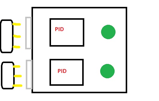
OK this is a P-J diagram I found from a thread and modified it to what I THINK I need.
PJCopy.jpg

This is what I envision when I think of a control panel I want if I wire a 120 V outlet into it for my pump's AC adapter
Idea.jpg
 
OK this is a P-J diagram I found from a thread and modified it to what I THINK I need.
PJCopy.jpg

This is what I envision when I think of a control panel I want if I wire a 120 V outlet into it for my pump's AC adapter
Idea.jpg

I am very interested in this, my question is how do you plan on supplying 70 amps to that spa sub panel? Also, you will need a couple SSRs and then heatsinks in there from what I remember.
 
Yes the SSRs are the white square things above the PIDs in the diagram.
I was going to do just 50 Amps, but since they have that 70 amp panel, why not?

I was thinking the spa panel acts like the breaker, so wouldn't that just be wired into the house circuit? Otherwise I would just wire it into the panel with a 50 (or 70) breaker
 
Spa panel is to provide GFCI protection. Panel circuit breaker is to provide circuit protection. You could have the spa panel provide circuit protection too, or have a GFCI circuit breaker in your main panel and only need one or the other.

The circuit breaker needs to be rated to exceed your maximum expected current draw, and your electrical wiring needs to be sized to match your circuit breaker size. If you install 50a rated wire and a 70a rated breaker, and you get a short, you could melt your wire and burn down your house before the 70a breaker trips.

In your hand sketch - the power supply from your spa panel should end in a female end, and your panel must have a male receptical. Just like you'd see on a normal extension cord. Having a male end on that side of your cord coming from the spa panel means you'd have exposed, powered conductors - not safe.
 
How would I make the spa panel be my panel protection? That way its plug and play and removable
 
Since spa panels seem to be cheaper than actual breakers, I'll go that route, plus I can just unwire it from my fuse panel when I leave this house.
The basic 50A panel was $72 on Home depot's site, but I saw this one for $78

It has 70 amps plus a 4 prong plus a 120V outlet

So my pump's wiring could go into the 120V side and my two elements could go into a single plug into the 4 prong. Less wiring is better for looks.

Thoughts?

That panel won't work. The 50A breaker isn't GFCI. There's just a 20A GFCI outlet installed in the box. This is the one a lot of people use and it's listed at $66: http://www.homedepot.com/p/Midwest-...el-Disconnect-with-GFI-UG412RMW250P/100686230

To make mine removeable, I had a 50A breaker installed in my main panel and then had a regular 50A outlet installed in the garage. Then I installed another 50A outlet in the spa panel with a 6' cord attached. My control panel will plug into the spa panel and then the spa panel will plug into the garage outlet.
 
Why not just wire the spa panel straight into the panel? Doesnt the spa panel have a breaker?

EDIT: If you have to plug the spa panel into another 50A outlet then wire that into a 50A breaker in the panel, wouldn't it be cheaper just to wire an outlet to a GFCI breaker in the panel? Otherwise it seems redundant

For some unexplained reason the cost of a 50a regular breaker plus a 50a GFCI spa panel (that has a 50a GFCI breaker) usually runs less than a 50a GFCI breaker. Also, the "pluggable" solution is portable, not part of your permanent house wiring, and technically then does not require a permit or an electrical inspection.
 
Oh so you NEED both a regular 50A breaker in the panel plus the GFCI breaker in the spa panel?

I was thinking you only needed one breaker between control panel and house panel
 
I'd like to get this started in the next week or two. Can anyone explain why some people have random fuses between here and there? Also, what is the "coil" in the wiring diagram? A resistor?
 
I'd like to get this started in the next week or two. Can anyone explain why some people have random fuses between here and there? Also, what is the "coil" in the wiring diagram? A resistor?

I'm not an electrician so take this for what it's worth.

The fuses are intended to protect the components (i.e. your PIDs). The breakers like a 50A GFCI are there to protect your wiring. GFCI adds some additional protection when working in wet locations like a brewery.

The coils act as relays for high current. Think of it this way, the heating elements require significant amounts of electricity. In a traditional light switch you make a physical connection from open to closed to turn on the light. With a coil/relay/contactor you run a smaller amount of current from your source through a switch into the coil to activate the "coil" for your high current device. Activating the coil causes the circuit to close and provide power to your element. One benefit of a coil/relay/contactor is that you can use a switch that isn't designed to carry all of the current required for your heating elements. If you look at the switches commonly being used on e-builds they are usually rated for 1A of current. However, a 5500W element will draw roughly 23A. In order to use the 1A switch, you need to use coil/relay/contactor that can handle the applicable load.
 
Ok thats clear now. Do these coils come from auber or are these hardware store buys?
 
I'm not sure you'll find contactors at your local Home Depot. You can get them from Auber, Amazon, or a number of other places. I wouldn't endorse any specific vendor. You need to make sure that it is rated to carry enough current for your heating elements and that the coil side of it is applicable to your circuit. The contactors that you find vary in how much voltage is applied in order to close the circuit.
 
Is there anything wrong with using the SPA panel as the box to place everything else in?

By that I mean, you could have your PID/SSR, heatsink out the side etc.... then your main on/off would be the spa panel shutoff right?
 
Back
Top