• Please visit and share your knowledge at our sister communities:
  • If you have not, please join our official Homebrewing Facebook Group!

    Homebrewing Facebook Group

RIMS for Dummies

Homebrew Talk

Help Support Homebrew Talk:

This site may earn a commission from merchant affiliate links, including eBay, Amazon, and others.
Interesting information on thread type.

Where did you find a 1" NPSM pipe tap? I can't imagine who would have one. And would guess the cost would be too high for a single use to buy one.
 
I built mine with all npt fittings and could not get my heater element to catch more than the first thread, so I bought a cheap tap on ebay to re-cut the bushing for the heater element to nps. I did not worry about buying a high dollar tap since I would only need it once. It definitely has a few more rims tubes in it.
 
Interesting information on thread type.

Where did you find a 1" NPSM pipe tap? I can't imagine who would have one. And would guess the cost would be too high for a single use to buy one.

A local fabrication shop has one. They quite often make handrails out of pipe and the 1" nominal pipe (1.315" diameter) is used for secondary supports.

An alternative would be to get an NPT tap from a plumbing shop and simply cut the threads one or two turns deeper. This would make the end of the thread a bit loose, but there is still sufficient engagement to make the mechanical joint, allowing the gasket to make the seal.
 
Check Ebay
fcb_electronics-item#360227864158
this is what I got and a lot cheaper
Cheers
Paul;)
 
Could someone tell me the difference between the

Auberins syl-2352 and the syl-43x2

Is size the only difference or are there some control features that I'm missing?

Edit: I see you can use the alarm out on the syl-43x2 to run an SSR. That being said is the 2352 suitable for this RIMS setup?
 
Could someone tell me the difference between the

Auberins syl-2352 and the syl-43x2

Is size the only difference or are there some control features that I'm missing?

Edit: I see you can use the alarm out on the syl-43x2 to run an SSR. That being said is the 2352 suitable for this RIMS setup?

The SYL-XX52 have SSR outputs, SYL-XX42 have Relay outputs. Other than that, for our purposes the difference is size.
 
I built mine with all npt fittings and could not get my heater element to catch more than the first thread, so I bought a cheap tap on ebay to re-cut the bushing for the heater element to nps. I did not worry about buying a high dollar tap since I would only need it once. It definitely has a few more rims tubes in it.

Could you provide a link for the tap you bought? I'd like to get one, too. Thanks.
 
I was able to screw my element into NPT fittings. A little teflon tape. I put the tee into my vice and used some elbow grease. Thankfully it worked. I'm not sure why yours gave you such a hassle!
 
I was able to screw my element into NPT fittings. A little teflon tape. I put the tee into my vice and used some elbow grease. Thankfully it worked. I'm not sure why yours gave you such a hassle!

+1. Gasket squeezed tight all the way around. No leaks during a 90 minute test.
 
Sawdustguy,

I was reading some of your post over on the brewtroller page and I had a few questions.

Am I correct in thinking that you cannot use an RTD in the brewtroller setup? If this is the case, can you use the brewtroller thermocouple with a PID? I just want to make certain that I have components that can be easily swapped between systems if I choose to go to a brewtroller setup.

Also, is there any way to automate using PID, and SSR's. Some PID’s have dual output (using the alarm) could this be used to control an electric valve? If not, is this RIMS for dummies completely manual in terms of turnings pumps on.

I know I'm kinda all over the place on this but I just want to get an idea of what to purchase instead of buying components and then realizing they will not do what I want them to do.
 
There is a prototype board for RTD temp sensors that CodeRage is working on, I know he had it functioning but I believe he is still working on the code. Brewtroller doesn't use thermocouples; it utilizes OneWire digital sensors. They won't work with a PID.

Sawdustguy,

I was reading some of your post over on the brewtroller page and I had a few questions.

Am I correct in thinking that you cannot use an RTD in the brewtroller setup? If this is the case, can you use the brewtroller thermocouple with a PID? I just want to make certain that I have components that can be easily swapped between systems if I choose to go to a brewtroller setup.

Also, is there any way to automate using PID, and SSR's. Some PID’s have dual output (using the alarm) could this be used to control an electric valve? If not, is this RIMS for dummies completely manual in terms of turnings pumps on.

I know I'm kinda all over the place on this but I just want to get an idea of what to purchase instead of buying components and then realizing they will not do what I want them to do.
 
Yeah I saw the OneWire digital sensor, how accurate are they? I've read some other forums where people were having issues with them reading ambient temps correctly.

How do you calibrate them, and how are they implemented in the system? I see they can be placed into a thermowell, do you them fill the well with silicone?
 
Steelers77,

Sawdust hope you dont mind if I field this one real quick. Pt100 RTDs are going to be an option very soon. Its an external module with inputs for 4 RTDs that will interface with the BrewTroller. Once complete it the firmware for the BT will need to be modified but the guys over there are very good about supporting new hardware quickly.

Theres a thermocouple version too that is working to some degree but it is way out on the back burner.

Edit- Damn you pickles, waited all day to answer this and you jump right in front of me :p j/k

The Dallas one wire sensors are calibrated from the factory. You could write your own calibration curves and offsets, personally I prefer not to use them. People have had problems with their one wire networks that are either too long or have too many devices attached. We've always been able to work through it and get folks running but it can be a headache. To be fair, some people have had great success with them and find them a reliable option.
 
They are very accurate. I haven't had to calibrate any of the eight I use. They fit perfectly snug into a 1/4 thermowell no need for silicone and transmit data very quickly.
 
If there is a prototype in the works for an RTD based system I may just go ahead with my rims tube build and expand from there.

I work with a controls specialist who has a PHD in process engineering and he has offered to help me with my build build I like to get the input of the community so I don't bother him too much with my Sh*t.

Sad thing is I have an electronics engineering degree but I have not used in 10+ years. You tend to forget a lot of things when you don't use them often. Damn Environmental Engineering position!
 
I have modified Sawdustguy's original drawing to suit my build (and this post has been a great help - thanks all).

Main thing I did is use a newer PID from Auberins and a different sensor. I want to be able to switch my pump on separately so I can use it after the mash for moving wort around. But - I also want to make sure that the heater cannot come on unless the pump is running - as a safety issue. I put in a single pole isolation relay with a 125V coil - and 20A contact rating.

I'm not sure how to wire the coil. So, my question is, for any tech savvy brewers out there - should I run the relay coil (4K4 ohm resistive load) down to neutral as per this diagram, should I run it in series with the pump? Any help much appreciated.

RIMS2.jpg


Ian
 
...
I'm not sure how to wire the coil. So, my question is, for any tech savvy brewers out there - should I run the relay coil (4K4 ohm resistive load) down to neutral as per this diagram, should I run it in series with the pump? Any help much appreciated.
How about doing it this way. It will require a DPDT Center Off switch. It should give you the control you want. If the element is energized the pump is also. The switch in the other position energizes the pump and disconnects power to the element. (BTW -With a 120V system you do not need to switch the neutral.)


RIMS3.jpg


Hope this helps.
 
How about doing it this way. It will require a DPDT Center Off switch. It should give you the control you want. If the element is energized the pump is also. The switch in the other position energizes the pump and disconnects power to the element. (BTW -With a 120V system you do not need to switch the neutral.)

Hope this helps.

I thought about doing that way - actually, just using one pole of the DP/ST switch to switch the pump, the other to switch the heater feed. The reason I didn't is because these are illuminated switches. I assumed there had to be a neutral at the switch for them to illuminate. I'm not sure thought as there is no iring explanation for the illumination...
 
I thought about doing that way - actually, just using one pole of the DP/ST switch to switch the pump, the other to switch the heater feed. The reason I didn't is because these are illuminated switches. I assumed there had to be a neutral at the switch for them to illuminate. I'm not sure thought as there is no iring explanation for the illumination...
If you can do it with a DP/ST switch I'd like to see that. I cannot even begin to imagine how you would be able to control the element and the pump, the way you want, using it.

For the switch illumination you do need the neutral at the switch, however, you do not need to switch it. It is there only to complete the circuit for the lamp.
 
Well this seems to be the right place to ask. I'm putting my first build together and want to go RIMS.

I seem that most are using 120 ULW elements. I have 220/50A available and plane to do an electric BK as well. Does anyone have experience running this style of RIMS with a 220 say 5500w or 6000w element? I have read all 57 pages now and seems that most people feel the PID can switch the element on and off fast enough to keep the set point without scorching.

I am debating building one with this style or just buying one of brewersequipment.com ones (made longer for the larger element) but I don't like how the temp sensor seems to be out of the flow path with the brewersequipment one.

What do you think?
 
What do you think?

I think the PID will do a fine job of switching the element on and off to maintain your temps w/o scorchng. The key is to tune the system so it doesn't overshoot the temperature. Most PIDs have an auto learn feature that will tune the PID based on the system it is controlling.
 
I cannot even begin to imagine how you would be able to control the element and the pump, the way you want, using it.

QUOTE]

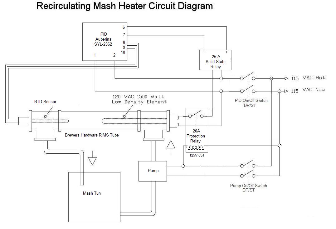
I'm not following what you mean. There's no real difference between what you re-drew and my original in term of energizing the protection relay. Good point about not switching the neutral - but is there a down side to doing so?

When the pump switch is closed - the pump will run and the protection relay will be energized, completing the circuit from the PID output relay, allowing the PID to switch the heating element based on the PID settings. If the pump is not turned on, the element cannot heat - which I see as a safety feature for not being able to heat wort that is not moving.

My original question was - should I have the protection relay coil in parallel to the pump as per my original drawing the the following one (with the DP/DT)?

The reason for this question is - if the protection relay coil was in series with the pump, and were the pump circuit to fail, the the heater would not be able to be energized. This seems that it would provide greater protection, but I don't know if I can put the resistive load (4K4 ohms) of the coil in series with he pump and have both the pump and coil function correctly.

Ian
 
I think the PID will do a fine job of switching the element on and off to maintain your temps w/o scorching. The key is to tune the system so it doesn't overshoot the temperature. Most PIDs have an auto learn feature that will tune the PID based on the system it is controlling.

My PID does a good job, it does not overshoot and heats a 10 gallon mash about 3 degrees per minute in a 10 gallon round cooler. I ran it on the auto tune function with just water in the mash tun. It heats to the point where the water passes the set temperature, then let's it cool - it does this three times and depending on the response time, the AI will calculate when to turn off the heater so that it will not then rise above the set temperature. It is very easy to use.

I currently have a long 240V heater running at 115V. I have just bought a Stout Tanks 20g mash tun with RIMS tri clamp fittings and the tri-clamp RIMS tube from Brewershardware.com.

Consequently, I am re-doing my control box in a newer box and adding a DIN timer to time the steps. I want to add a protection relay and interlock the heating element to the pump to prevent heating when the wort is not pumping - hence the diagram and question a few posts ago.

My current RIMS tube is soldered copper and not really easy to clean - I'm looking forward to using the SS tri-clamp one.
 
I am debating building one with this style or just buying one of brewersequipment.com ones (made longer for the larger element) but I don't like how the temp sensor seems to be out of the flow path with the brewersequipment one.

What do you think?

I went with the brewersequipment on and it works quite well...have two brews under my belt with it already.

The newer versions that he is putting out has the outlet more towards the temp sensor...so a 4 inch sensor will be in the flow, no problem.
 
...
The reason for this question is - if the protection relay coil was in series with the pump, and were the pump circuit to fail, the the heater would not be able to be energized. This seems that it would provide greater protection, but I don't know if I can put the resistive load (4K4 ohms) of the coil in series with he pump and have both the pump and coil function correctly.
Short answer - You cannot put the coil in series with the pump. With that wiring setup, neither will work and both will fail.
 
Great read, only took me like 3 hours lol.

I'm about to go from 3 gallon BIAB batches to 10 Gallon batches and I'm definitely going to use a RIMS setup similar to this. I have plenty of questions spread across the site, but this one I think belongs here.

Is anyone using 2 heat exchangers (RIMS Tubes, whatever)? My idea is basically heat HLT with #1, Mash with #2 while heating sparge with #1, Fly sparge, Boil with 1. And as I get used to the process I can begin heating the HLT for a second batch.

They will both be 240V elements with PIDs, I'll use manual mode for the boil.

Any problems with this?

I don't know of anyone that's boiling with a RIMs tube and I think it would cause you some problems...

1. - Typical magnetic pumps we use don't work so well with boiling liquid, they tend to cavitate.

2. - You can certainly generate enough power to boil the small amount of liquid in the RIM's tube, but I think you'd have a hard time controlling it. In a closed vessel, the RIMS tube, you'd generate steam which means pressure.

Why not just mount an element in your HLT/BK and use RIM's for maintaining the mash temps as it was designed?
 
Back
Top