I cannot even begin to imagine how you would be able to control the element and the pump, the way you want, using it.
QUOTE]
I'm not following what you mean. There's no real difference between what you re-drew and my original in term of energizing the protection relay. Good point about not switching the neutral - but is there a down side to doing so?
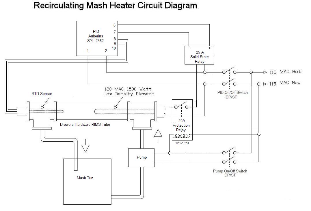
When the pump switch is closed - the pump will run and the protection relay will be energized, completing the circuit from the PID output relay, allowing the PID to switch the heating element based on the PID settings. If the pump is not turned on, the element cannot heat - which I see as a safety feature for not being able to heat wort that is not moving.
My original question was - should I have the protection relay coil in parallel to the pump as per my original drawing the the following one (with the DP/DT)?
The reason for this question is - if the protection relay coil was in series with the pump, and were the pump circuit to fail, the the heater would not be able to be energized. This seems that it would provide greater protection, but I don't know if I can put the resistive load (4K4 ohms) of the coil in series with he pump and have both the pump and coil function correctly.
Ian


![Craft A Brew - Safale BE-256 Yeast - Fermentis - Belgian Ale Dry Yeast - For Belgian & Strong Ales - Ingredients for Home Brewing - Beer Making Supplies - [3 Pack]](https://m.media-amazon.com/images/I/51bcKEwQmWL._SL500_.jpg)


