iSpindle - DIY Electronic Hydrometer

Homebrew Talk - Beer, Wine, Mead, & Cider Brewing Discussion Forum

Help Support Homebrew Talk - Beer, Wine, Mead, & Cider Brewing Discussion Forum:

This site may earn a commission from merchant affiliate links, including eBay, Amazon, and others.
Forgive me, but side question with Ubidots. My dashboard has a widget for gravity. Can I create a widget that gives me specific gravity instead of Plato?

Yes you can. You just need to create a new variable on the device page with a derived expression formula that converts the Plato reading to S.G. Then, add that widget to the dashboard.

Below is what my derived expression looks like

Screenshot_2020-09-28 Ubidots Devices.png
 
Yes you can. You just need to create a new variable on the device page with a derived expression formula that converts the Plato reading to S.G. Then, add that widget to the dashboard.

Thank you! I take it I should add a Synthetic variable? For your expression, you're using tilt and not gravity?
 
Last edited:
I'm using Ubidots which seems to work great, although I would prefer an app on my mobile device (especially since someone on this thread suggested Ubidots will be going away from education)
Theses app do not work by itself. They just show the data on Ubidots.
You may have yuur own server at home, a Raspberry with Craftbeerpi, frementrack or other soft.
 
Thank you! I take it I should add a Synthetic variable? For your expression, you're using tilt and not gravity?

It's been so long since I set it up, I would have to go back and think about the way I organized the expression. But, yes it converts the tilt variable to S.G.

It's actually the Degree 1 polynomial that is provided by this spreadsheet. Since, I just use a 2 point calibration every time I brew. I do the following:
  1. Write down the tilt in plain water
  2. Sanitize the iSpindel
  3. Throw the iSpindel in fermenter
  4. Take a gravity reading
  5. Use the tilt angles @ 1.000 and O.G. in the spreadsheet linked above to get the Degree 1 Polynomial.
  6. Enter that Polynomial in the Derived Expression field in Ubidots to get the S.G. Variable.
Hope that helps.

Also, this is another reason why I am going to be moving to Fermentrack. I believe it has the calibration procedure as a built in function.
 
After bragging about just how reliable and accurate my iSpindle is and in the midst (2nd day) of making my third batch since building it, yesterday lunch it stopped reporting from inside my FV. It is configured to report every 15minutes, to Ubidots, from my batch of red wine.

I opened up the FV, took it out, rinsed it, switched it off and back on, tried pressing reset, went into the configuration and checked that, off and back on again, lots of waiting to see if it was reporting and nothing. 15 minutes is a long time to wait for it to flash and a long time to wait for an update to Ubidots, so then I thought best change the report interval to 60 seconds. At that it sprang back into life, so I changed the reporting back to 15 minutes (900 sec), waited and watched to make sure it carried on reporting then yesterday evening put it back in the FV. It has worked fine overnight.

I may have found out what happened, because it just happened again - I powered it up and no data appeared in Ubidots, until I went into the iSpindel config and simply saved the config without making any changes....

My home network is quite busy with around 30 items on it, though not all needing use of it at the same time. I had several items on static IP's, but many more relying on the DHCP of my main router, to allocate temporary IP's. I think the iSpindel must remember the temporary IP it was allocated and tries to reuse the same IP once powered up. A router will ignore the iSpindel's attempts to send data, if its IP has been reallocated to something else. Even a couple of laptops were tending to lose their temporary IP's and be unable to connect to the Internet.

I have now set everything on my network to be allocated static IP's, by the router, including the iSpindel. All is working well at the moment.

I will just add, that the way I built my own V4 it has proven to provide very stable with predictable values of tilt and calculated SG, since calibrating, once it had settled. Just to remind how I built mine....

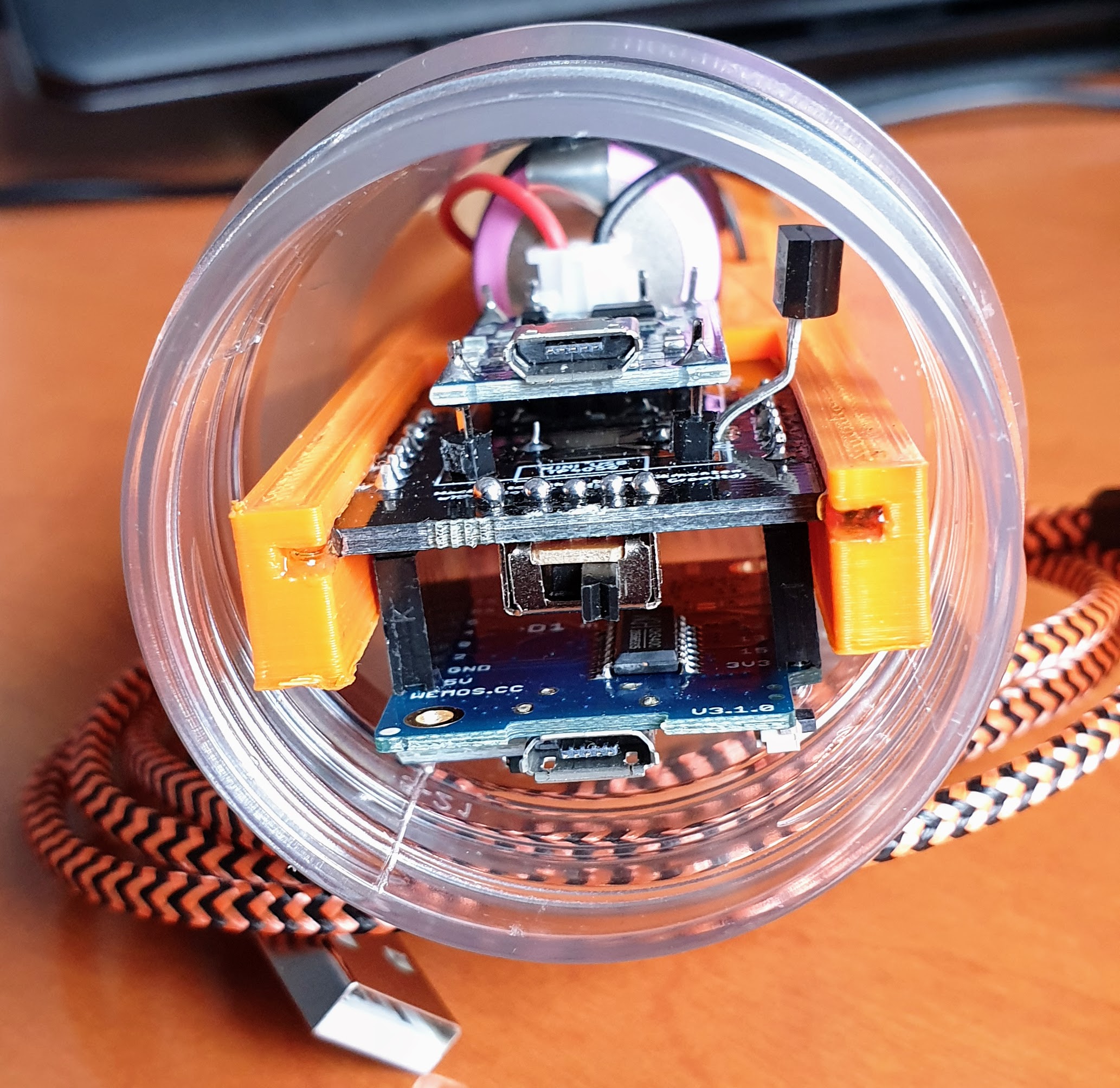
I didn't use a battery holder, I stuck the battery to the PCB with strong double sided tape, mounted as low on the PCB as possible, then soldered wires to it, kept reasonably short so they cannot move. The weights to calibrate it, again I stuck on with double sided tape either side of the battery, again as low down the PCB as possible. Aside from using the weights for calibration, I also adjusted the weights side by side, so the PCB would lie horizontally side to side, with battery below the PCB. My PCB is not a tight fit in the container, in is able to move very slightly, but the major weights are quite firmly fixed to the PCB, so there is no possible variation in the relationship between them and the CofG.

My assumption is, that the PCB always flops neatly into the relationship in which I calibrated it.
 
I still would be interested if the cap design could be improved at all.

Look for drinks in your local supermarket, with the identical cap - hopefully you can enjoy the contents, before repurposing the cap. Remember the petlings are sold commercially to be heated and blown up to be used by manufacturers as drinks bottles. I have found a few spare caps, since building my iSpindle, though I haven't needed to use one yet.
 
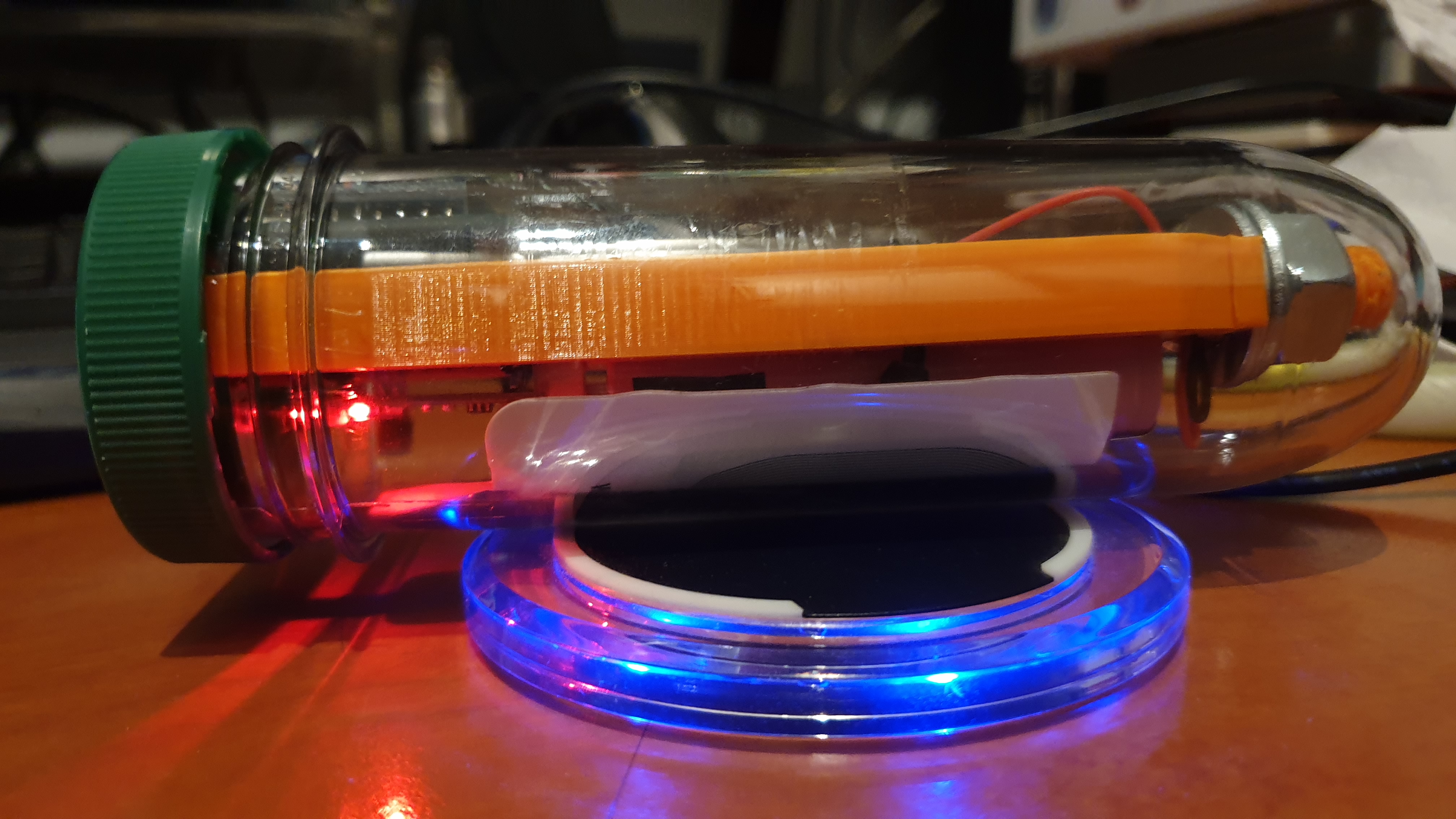
Just a thought, might the reed switch not be triggered by wireless charging?
I have really bad experiences with wireless charging. After 5 to 10 minutes of wireless charging the thing became so hot that the tape on the lids of the battery started to melt. So no wireless charging for me anymore.
20190629_014051.jpg
20190629_182653.jpg
 
Diode removal - Wemos D1 mini pro

I bought a set to solder the ispindel yourself from someone containing all parts. I have the cherry phllip 4.0 board and the Wemos d1 mini pro (brand: rainsun), this is where my question is.
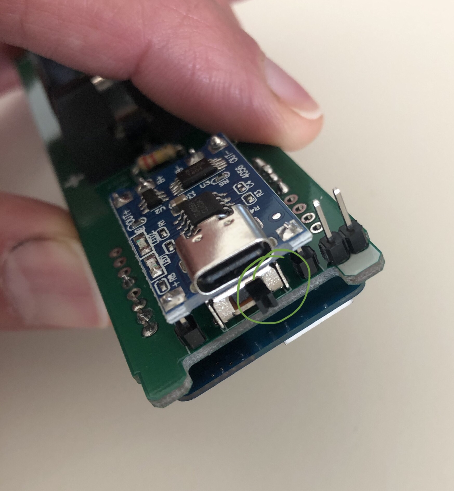
I want to remove the diode, but it is somewhere else than on the other d1 boards. Can you tell me which is the diode to remove to prevent charging with 5v
094AE1E0-E3B2-4A4C-A8FD-A2FE7BA25C4C.jpeg
 
Last edited:
Diode removal - Wemos D1 mini pro

I bought a set to solder the ispindel yourself from someone containing all parts. I have the cherry phllip 4.0 board and the Wemos d1 mini pro (brand: rainsun), this is where my question is.
I want to remove the diode, but it is somewhere else than on the other d1 boards. Can you tell me which is the diode to remove to prevent charging with 5v

According to iSpindel Assembly | Open Source Distilling, follow the leftmost trace from the USB port, which looks like it puts your diode just up and to the right of the USB oddly enough. That first piece the trace hits on the left is a capacitor. Also, if you follow the trace on the other side of that diode, you'll see it hits another capacitor and then heads to the 5V post, so that should be further confirmation it's the right one.
 
According to iSpindel Assembly | Open Source Distilling, follow the leftmost trace from the USB port, which looks like it puts your diode just up and to the right of the USB oddly enough. That first piece the trace hits on the left is a capacitor. Also, if you follow the trace on the other side of that diode, you'll see it hits another capacitor and then heads to the 5V post, so that should be further confirmation it's the right one.
Thank you, I read something similar, but wanted to post my specific picture so someone could tell me I am correct (in this case the red component to remove). I don’t want to try out and come to the conclusion it was something else.
Si it should be the one circled in red, comming from from the yellow usb spot to the red ‘diode’ to the green marked 5.0v.

4378360D-6D23-44AB-A58D-A3D9EFB55382.jpeg
 
Hmm, you've got a D1 Mini Pro there not a D1 Mini and for the iSpindle that may not be the best choice. It might work, but works best with an external aerial, hence the connector in the top left corner. I've used a Pro in another project without an external aerial and it was fine but it might limit your range.

Regarding the removal of the diode, unless it on the other side of the PCB then it's just above the right hand corner of the USB port on the D1 Mini. I don't have easy access to my D1 Mini Pro to check until the begining of next week I'm afraid.


Chris
 
Thank you.

Can anyone tell me if the board is currently in the on or off position (green circle on the first picture)? In that case I won’t need to remove the part before ChrisThomas can confirm it is indeed this part and proceed with charging and flashing the Wemos.

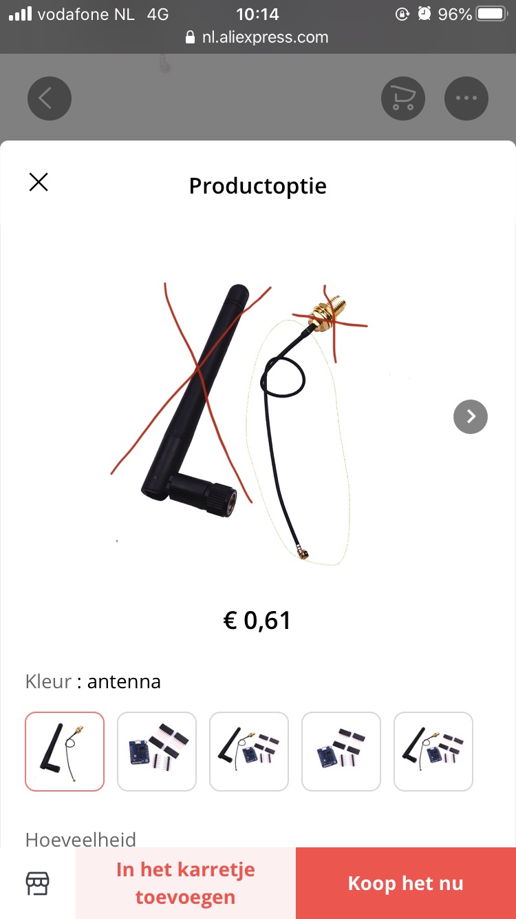
Second, I receive a message the antenna of the mini pro is not that good compared to the mini, I should resolver the 0 ohm resistor and place it in the green position so I can make use of the external antenna, which I will need to buy (picture attached). Has somebody experience on this part? Can I cut of the large golden connector and only use the wire and the small connection to fix it to the board?

A lot of questions and I hoping on a lot of positive replies, thank you for replying!

8FF83426-BFC3-4EAA-837D-A397CDE88B88.jpeg
BF3C042C-55E3-4DBC-A75B-9582A956C8B5.jpeg
794D32BA-8717-45D0-BD77-3317762A7EE6.jpeg
 
Your switch is in the off position. Nearest the two reset pins = off.

The antenna you are suggesting buying is of no use at all to you. If you intend mounting the iSpindle in a pet bottle. the antenna needs to be inside the pet. If I were you, I would look at trying to solder a few inches of tiny, insulated wire to the centre terminal of the plug on the pcb, to act as an antenna. 31.2mm is the calculated length needed for wifi.

That is 31.2mm of unscreened, but insulated wire length. For instance you could use that plug and its screened antenna lead, by cutting the antenna off and cutting back the outer screening of the coax to expose 31.2mm of the inner core to act as the antenna. However, why bother when a simple piece of thin insulated wire, 31.2mm will work just as good?
On the pcb's with integrated antenna, the antenna can be seen as a zig-zag track on the pcb, total length of the zig-zag track will be 31.2mm.
 
Thank you HarryB,

In that case I will still need to reposition the 0 ohm resistor or remove it and place some solder to make a bridge like the green proposed.
Do you really foresee problems with the ceramic antenna? Otherwise it is better for me to reorder a Wemos d1 mini and replace it, the 31,2 mm is strict I assume not sure if I can cut and mount it in that precision.
Understood correctly the cable of the antenna with to coupling which can be used for mounting to the pcb is screaned against radiation, exact opposite as we want to achieve?
I think I will start charging the batterij in this off position with the usb c (battery charger pcb) and than flash it with the other micro usb side on the Wemos.
Will see how the WiFi is as I plan to place a router in the near (old one still lying around).

You are also convinced the red component is the entrance diode which should be removed (as a security to not over charge)? If I only use the usb c charger for charging, will I be at risk when sticking usb in my computer when trying to flash?

Thank you.
 
1. ....diode which should be removed (as a security to not over charge)? 2. If I only use the usb c charger for charging, will I be at risk when sticking usb in my computer when trying to flash?
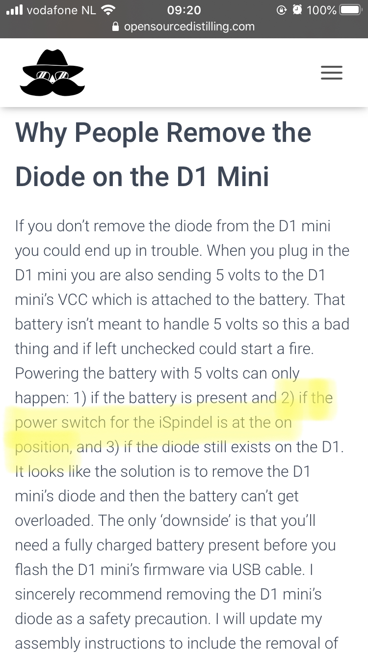
1. The diode is to be removed, not to prevent overcharging, it is to be removed to prevent the battery getting 5V directly when flashing thru the usb on the wemos. So you'll have to remove the diode before flashing, otherwise you'll probably blow up the wemos and have a serious danger of fire and/or an exploding battery. I don't know if you can flash it that way with the battery out and the diode still on there however.
2. You can charge the battery that way, yes, no risk there, but whatever you do don't flash it with the diode on there and the battery attached!!!

I flashed my wemos(mini) before soldering it together. Once the iSpindel is put together you can flash it OTA thru your wifi connection with the iSpindel in configuration mode. So I didn't remove the diode but I don't use the usb port on the wemos anymore, in fact I closed it up with a rubber plug so I can't make the mistake of plugging a charger in it, both ports are on the same side, I only use the usb port on the TP4056 charging port to charge it.
I am using the original design, not the one you have, with an iSpindel @Mikmonken v2 pcb from pcbs.io(which they don't sell anymore) I also have the @gromitdj iSpindle_V21 based on the Mikmonken V2. Planning to solder a few together in the coming weeks.
20190510_190420.jpg
20190510_194229.jpg
).
 
1. The diode is to be removed, not to prevent overcharging, it is to be removed to prevent the battery getting 5V directly when flashing thru the usb on the wemos. So you'll have to remove the diode before flashing, otherwise you'll probably blow up the wemos and have a serious danger of fire and/or an exploding battery. I don't know if you can flash it that way with the battery out and the diode still on there however.
2. You can charge the battery that way, yes, no risk there, but whatever you do don't flash it with the diode on there and the battery attached!!!

I flashed my wemos(mini) before soldering it together. Once the iSpindel is put together you can flash it OTA thru your wifi connection with the iSpindel in configuration mode. So I didn't remove the diode but I don't use the usb port on the wemos anymore, in fact I closed it up with a rubber plug so I can't make the mistake of plugging a charger in it, both ports are on the same side, I only use the usb port on the TP4056 charging port to charge it.
I am using the original design, not the one you have, with an iSpindel @Mikmonken v2 pcb from pcbs.io(which they don't sell anymore) I also have the @gromitdj iSpindle_V21 based on the Mikmonken V2. Planning to solder a few together in the coming weeks.View attachment 701905View attachment 701906).

Thank you for your support, according to this threat I could flash without removing, only need to make sure it is powered off:
Do you agree on this?

BF86EE7D-14AA-483F-BA0E-160E3EC26C5D.jpeg


Hereafter I will use the WiFi to update my Wemos and plug off the usb mini part and will only charge via de usb c.
 
I flashed my wemos(mini) before soldering it together. Once the iSpindel is put together you can flash it OTA thru your wifi connection with the iSpindel in configuration mode.

I have heard that can be done, but can you suggest where I can find a 'how to' please, for OTA updating. I don't need to update yet, I'm running the current version, but for the future please.
 
I have heard that can be done, but can you suggest where I can find a 'how to' please, for OTA updating. I don't need to update yet, I'm running the current version, but for the future please.

The same way you connect to change settings, there's an option in there for uploading a new firmware.bin file.
 
Thank you for your support, according to this threat I could flash without removing, only need to make sure it is powered off:
Do you agree on this?
Well I wouldn't risk it. But maybe someone else can clear this up?

However, I saw one flaw in that thread, you can in fact flash the iSpindel firmware onto the d1 mini right out of the box thru usb with nodemcu before assembling the iSpindel.
 
However, I saw one flaw in that thread, you can in fact flash the iSpindel firmware onto the d1 mini right out of the box thru usb with nodemcu before assembling the iSpindel.

That is how I flashed mine - just the bare d1, on its own before I began assembly, just connected to USB and flashed.
 
Thank you, I read something similar, but wanted to post my specific picture so someone could tell me I am correct (in this case the red component to remove). I don’t want to try out and come to the conclusion it was something else.
Si it should be the one circled in red, comming from from the yellow usb spot to the red ‘diode’ to the green marked 5.0v.

View attachment 701793
@Enkie Yes, I've have a look at my D1 Mini Pro and that is the diode to remove. Regarding the aerial, I'd suggest to try it first without making any modifications. For my application it's range has been not nearly as good as a D1 Mini, at least I assumed that was the difference? If you get a limited range then look at the possibilities.

Chris
*edit: put the correct logic in!
 
Last edited:
Just build me a new one, but I made an error with the epoxy I pour in the tube to fixate the sled in there, I poured in 20 ml instead of 10 ml. Now the angle in plain water is 9.3 degrees. Anyone knows if this is an issue or is it still good to go?
20201016_164435.jpg
 
Hi Breebrew,

Depending on the answers, I think there was a range in which the sensor worked best, you could always try to ‘drill out weight‘ from the bottom..
Just make one or more holes from the bottom up into the tube and the epoxy, and stop before you go through all the epoxy, in that case the board with all components is still water tight.
However could difficult to clean out the small holes and potential contamination.
And you won’t win the beauty contest with this solution.

Good luck, hope you don’t have to make any changes.
 
However could difficult to clean out the small holes and potential contamination.
Thanks for a quick reply Enkie.

Yeah, well that's the thing, I am obsessed when it comes to contamination, don't want it and will do anything to prevent. I think I just try the thing out in my next batch, I can't think of anything why this angle in water is so important that it should be around 25 degrees other than that it may be too heavy, at 9.3 in plain water, to alter the angle in wort enough.
 
Rather than make holes, I would suggest grinding or filing it, followed by polishing it with finer and finer wet and dry paper - then at least you would have flat surface at the bottom and less susceptible to retaining contamination. I think the angle is important, to ensure that in a brew, it has an angle which is at its most sensitive and produces best accuracy where it is needed.
 
I made another one, with the exact same parts as the other one above and added 10 ml of epoxy, instead of 20 ml. The angle in plain water came out at 41 degrees:ghostly: So now I just added 3.5 ml of epoxy with a syringe so I could inject it below the hardware and not pour on it, now dry for 24 hours and measure again.
20201020_142820.jpg
 
Last edited:
I made another one, with the exact same parts as the other one above and added 10 ml of epoxy, instead of 20 ml. The angle in plain water came out at 41 degrees:ghostly: So now I just added 3.5 ml of epoxy with a syringe so I could inject it below the hardware and not pour on it, now dry for 24 hours and measure again.

That did the trick, angle comes out at a nice 20.5 degrees.

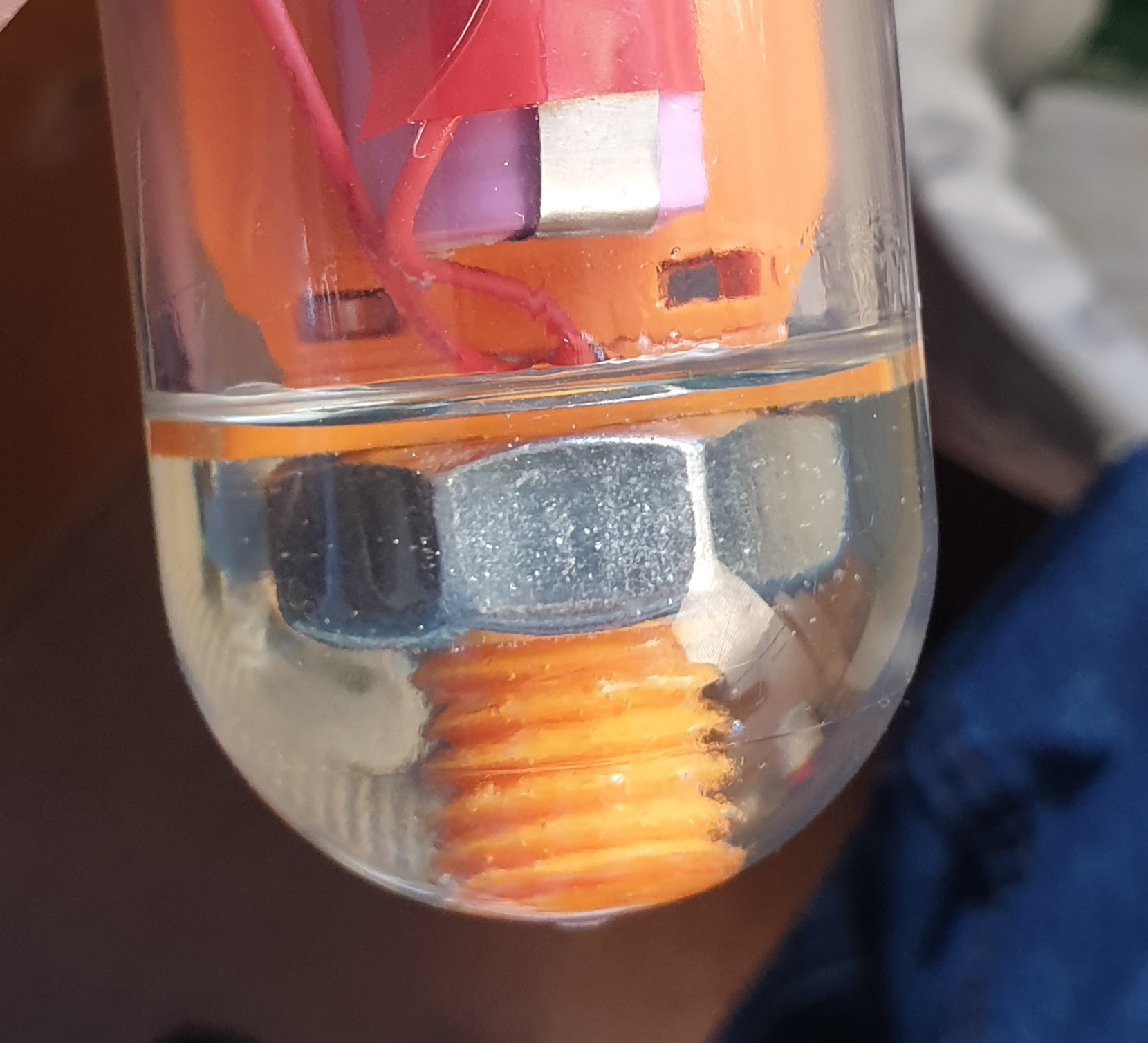
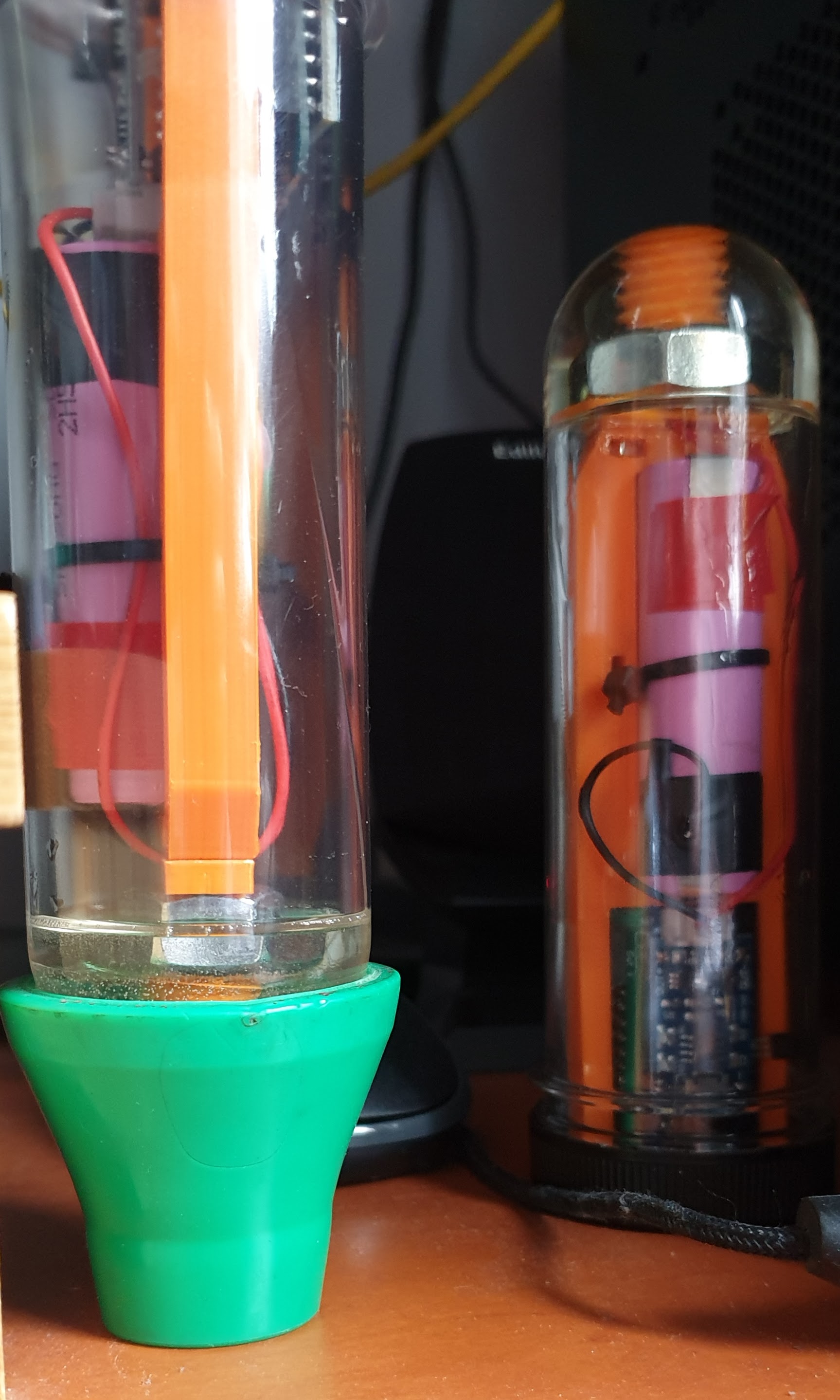
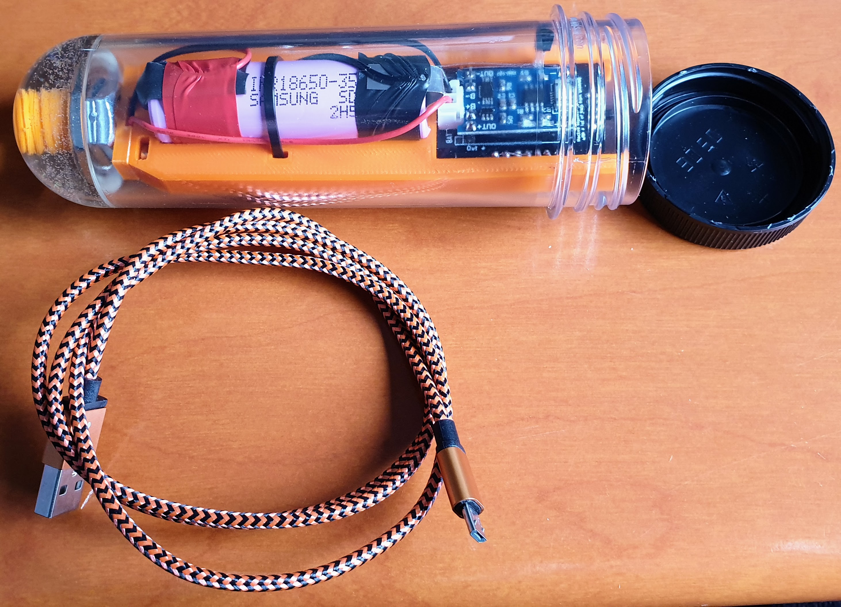
So I put this fully assembled and functional iSpindel up for sale for Europe based members.(I think it doesn't make much sense to ship it to the US because that would cost 30 euro on shipping alone).
Calibration on a flat surface and in plain water is done and I have a calibration excel sheet to come with it(by email or DM) where the angle in plain water is filled in along with a step list on how to go from there.
A 1m micro usb cable is included.

Price is 40 euros excluding shipping. Shipping within NL is € 6,75, in the rest of Europe it depends to which country and varies from € 13 - € 20 with track and trace. If interested DM me for details.

Parts a.o.:
  • Lolin ESP8266 D1 Mini V3.1.0
  • 3500mAh Samsung INR18650-35E
  • Petling 3DM1 with black lid from 3d-mechatronics.de
  • iSpindel @Mikmonken v2 circuit board from pcbs.io
  • DS18B20 temp sensor
  • GY-521 3 Axis gyro sensor
  • TP4056 5V 1A Micro USB 18650 battery charging board
  • Schottky BAT43 Diode 200mA 30 V (so no deep sleep issues)
  • mwx edition sled
  • 1 meter micro usb cable
The sled is fixed in the tube with epoxy to prevent the sled moving within the tube when for example you pull out the usb cable after charging the battery or even put it on/off with the switch. Otherwise you would have to calibrate every time the sled moved a bit, in this manner there is no need for that.

It needs to be said that I did not remove any diodes or leds, so firmware upgrades must be done over the air. (Some say you can do it thru the micro usb of the ESP8266 D1 mini as long as the iSpindel is switched off, but I wouldn't risk it).
According to the documentation the led on the GY-521 should be removed to save battery power but with a 3500 mAh battery you don't need to worry about that, plenty of juice. A big plus of not removing the led is that you can see if the iSpindel is on or off.

20201021_130657.jpg

20201021_130722.jpg

20201021_130757.jpg

20201021_130819.jpg

20201021_140925.jpg
 
A Brewspy question, for those using it please...

I have just begun using it and I am confused as to the graph updates. It is listing when the last data was received, all the past data, all up to date, but the graphs often lag well behind the data and I cannot see how to get the graphs up to date.

Are the graphs updated, when the server gets around to updating them, or is there some process by which I can force an update? Not complaining, just curious..
I actually asked that question to the developer a while ago, this was his answer:

"The graph shows the average gravity per hour so that's why the latest value does not exactly match the latest raw data value.

I do this so that the graph comes out smooth and does not end up with lots of spikes since the data from the spindel tends to fluctuate (and sometimes on very active fermentations these fluctuations are very big)
"
 
That did the trick, angle comes out at a nice 20.5 degrees.

So I put this fully assembled and functional iSpindel up for sale for Europe based members.(I think it doesn't make much sense to ship it to the US because that would cost 30 euro on shipping alone).
Calibration on a flat surface and in plain water is done and I have a calibration excel sheet to come with it(by email or DM) where the angle in plain water is filled in along with a step list on how to go from there.
A 1m micro usb cable is included.

Price is 40 euros excluding shipping. Shipping within NL is € 6,75, in the rest of Europe it depends to which country and varies from € 13 - € 20 with track and trace. If interested DM me for details.

Parts a.o.:
  • Lolin ESP8266 D1 Mini V3.1.0
  • 3500mAh Samsung INR18650-35E
  • Petling 3DM1 with black lid from 3d-mechatronics.de
  • iSpindel @Mikmonken v2 circuit board from pcbs.io
  • DS18B20 temp sensor
  • GY-521 3 Axis gyro sensor
  • TP4056 5V 1A Micro USB 18650 battery charging board
  • Schottky BAT43 Diode 200mA 30 V (so no deep sleep issues)
  • mwx edition sled
  • 1 meter micro usb cable
The sled is fixed in the tube with epoxy to prevent the sled moving within the tube when for example you pull out the usb cable after charging the battery or even put it on/off with the switch. Otherwise you would have to calibrate every time the sled moved a bit, in this manner there is no need for that.

It needs to be said that I did not remove any diodes or leds, so firmware upgrades must be done over the air. (Some say you can do it thru the micro usb of the ESP8266 D1 mini as long as the iSpindel is switched off, but I wouldn't risk it).
According to the documentation the led on the GY-521 should be removed to save battery power but with a 3500 mAh battery you don't need to worry about that, plenty of juice. A big plus of not removing the led is that you can see if the iSpindel is on or off.

View attachment 703322
View attachment 703323
View attachment 703324
View attachment 703325
View attachment 703327
SOLD
 
Thank you for your support, according to this threat I could flash without removing, only need to make sure it is powered off:
Do you agree on this?

View attachment 701912

Hereafter I will use the WiFi to update my Wemos and plug off the usb mini part and will only charge via de usb c.
Well I wouldn't risk it. But maybe someone else can clear this up?
....
I have to come back at my words there. I just build a couple of new iSpindels and measured the voltage at the pins that go to the battery with the Wemos usb of the fully build iSpindel attached to a PC. When the switch is in the off position I measure zero Volts, when in on position I measure a fluctuating voltage between 3.9 and 4.3 volts. So I think it is safe to say you can flash the wemos of a fully build iSpindel thru usb with a battery present AND the switch is in the off position.

However, if you make the mistake to attach the usb of the Wemos to a PC with a battery present and the switch in the on position you can end up blowing up the Wemos or in worst case scenario if left unattended for a while, set your house on fire.
 
I am having problems with flashing the ispindel,It does nothing after you push the flash button in the Flasher.
Can wait for an hour after reading the Log, came to the conclusion it is waiting for something..

The logg shows:
Note:Detect serial port changed.
Note:Auto MAP serial port.Port-->COM3

Note:Serial port connected.
Note:Begin find ESP8266.

the following message appears as a sequience during the 'flashing' but does not come to an end.
connect.world()
require("wifi")
require("gpio")


Capture GPIO.JPG
Capture wifi.JPG


Capture connect world.JPG
Log.JPG


Tried multiple USB cables, similair for the software, latest release but also some of the versions that was shown in a youtube movie explaining how to flash.
Hope somebody can help me out.

Kr. Pieter-Paul
 
Anybody using the ispindel in a sanke keg?

I have had bad luck with the Tilt. I can get a signal when the spear is removed, but once I cover up the opening to the keg with the spear or a 2" tri clamp fitting I don't get any signal.
 
It is very difficult any RF device works in a keg.
A completely closed steel can is a "Faraday jail" and no electromagnetic signal will go in or out.
You will have to drill the top and install a passive repeater antenna, a short length of coaxial cable with 3cm of the shield removed on each end.
 
I understand the whole faraday cage, but people use these with conicals... I guess the conicals have more gaskets for the signal to get out?

I could use a 2" sight glass in between the keg and the tri clamp fitting. That would be easier to sanitize than some coax cable. However that would make it too tall to fit in my fermentation chamber.
 
Last edited:
I am having problems with flashing the ispindel,It does nothing after you push the flash button in the Flasher.
Can wait for an hour after reading the Log, came to the conclusion it is waiting for something..

The logg shows:
Note:Detect serial port changed.
Note:Auto MAP serial port.Port-->COM3

Note:Serial port connected.
Note:Begin find ESP8266.

the following message appears as a sequience during the 'flashing' but does not come to an end.
connect.world()
require("wifi")
require("gpio")


Capture GPIO.JPG
Capture wifi.JPG


Capture connect world.JPG
Log.JPG


Tried multiple USB cables, similair for the software, latest release but also some of the versions that was shown in a youtube movie explaining how to flash.
Hope somebody can help me out.

Kr. Pieter-Paul

Gents and Ladies,

I received a new Wemos D1 mini Pro from the guy I bought the whole set from.
Inmediately before desoldering and soldering I tried to flash this Wemos, with a positive result.

It was apparently a faulty Wemos causing me problems flashing.
After it was in pace on the board, I calibrated (to horizontal) and then placed it in water of 25 degree Celsius, tilt: 19 degree...

Found the following solution to come to a 24,12 degree tilt, adding two mini nuts and some hot glue.


IMG_3239.jpg
IMG_3240.jpg


IMG_3241.jpg


Next step during the weekend will be a calibration on sugar water.

Thank you all for thinking along and I am glad it works!!

Kr. Pieter-Paul
 
Back
Top