Fermentrack: Fermentation monitoring & BrewPi-www Replacement for Raspberry Pi

Homebrew Talk - Beer, Wine, Mead, & Cider Brewing Discussion Forum

Help Support Homebrew Talk - Beer, Wine, Mead, & Cider Brewing Discussion Forum:

This site may earn a commission from merchant affiliate links, including eBay, Amazon, and others.
No LCDs? Oh no! I need to make everything as difficult on myself as possible.

I definitely know I want to go the RJ-45 Route. I ordered your SMD w/LCD and RJ-45 PCB this morning. So, when it’s time...I will solder a RJ-45 Jack to the “main” board. I need to purchase the RJ-45 breakout board you just linked. When I receive it, I will solder an RJ-45 Jack on that too. I can also connect up to 3, in my case, 3Meter DS18B20, 3-wire probes to that breakout board. Using an Ethernet Cable, I connect the breakout board to the “main” board. Will the 4.7K resistor come into play for me? If so, where does that get soldered in?

Hah. Two PSUs it is, then. Redundancy!

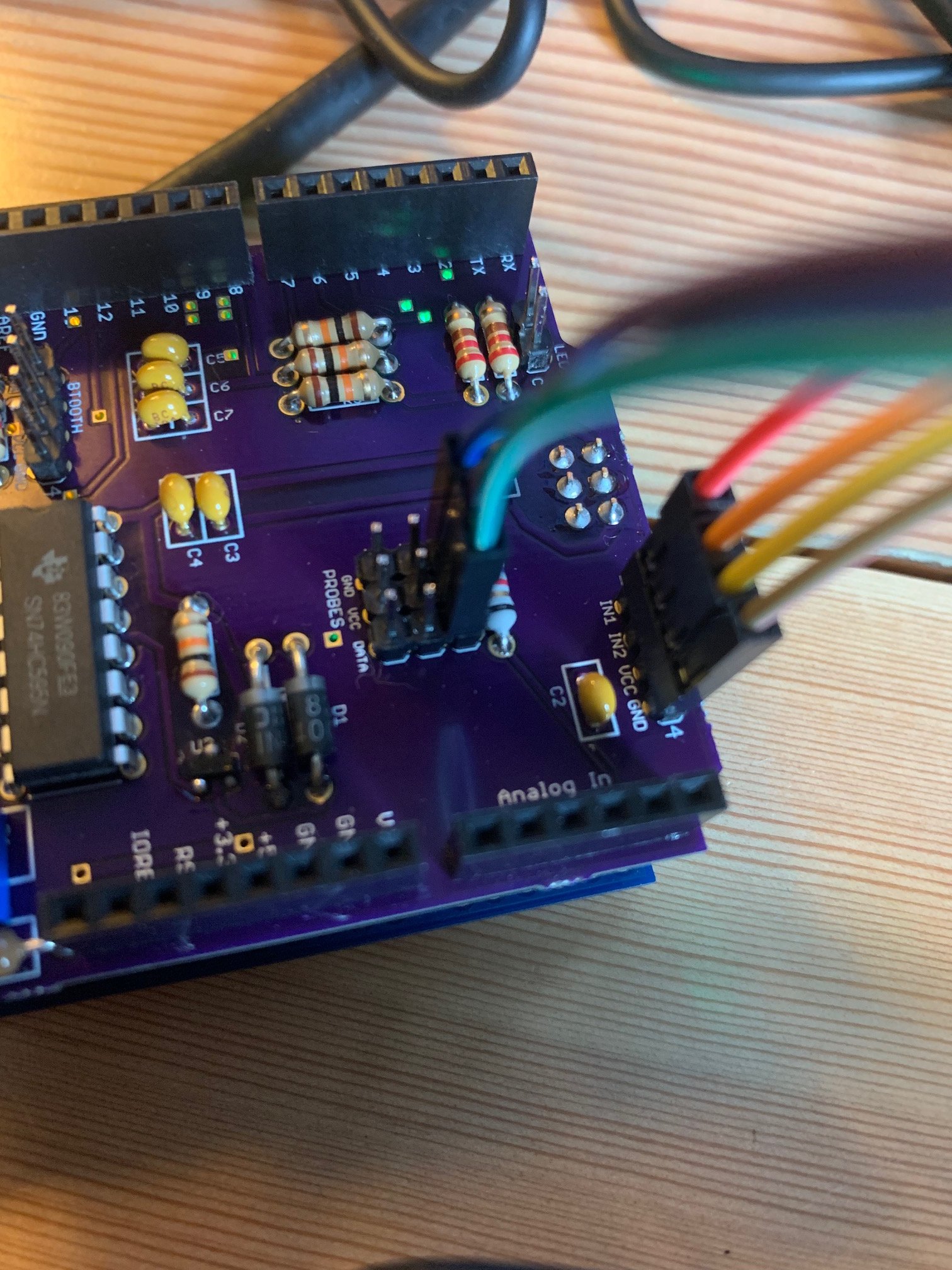
The 4.7k resistor is actually mounted on the "main" PCB as one of the SMD resistors. It can be either 4.7k or 10k if you want to cut back on parts - but if you go 10k, you may end up only being able to support 2 temperature sensors if you're doing 3m cables. The specific resistor you care about is labeled R1.

In Fermentrack, I got readings from both of them during the calibration process, and then put them in sanitizer to get ready for the batches. The last readings I have in Fermentrack are from them floating in the sanitizer. After switching to 30 minute update periods and putting in the fermenters, they've gone missing. I'm trying to not open them up and fish them out, but it's probably my only option at this point.

Unfortunately, it doesn't sound like a Fermentrack issue then in this case given what you're describing :(. It might be impossible, but would you potentially be able to move your wireless router closer to your fermenters to see if that causes them to get picked up?
 
Grab the sketch (below), save it as an .ino file, and load that into the Arduino IDE, then use the IDE to burn the Arduino. You may have to install one or both libraries (find them via Google) as I don't remember if either/both come with the IDE kit.

Hook up one probe and see what the sketch thinks it is.
Note you'll probably need to add a pull-up resistor...

Cheers!


Code:
#include <OneWire.h>
#include <DallasTemperature.h>


#define ONE_WIRE_BUS 18
OneWire oneWire(ONE_WIRE_BUS);

// Pass our oneWire reference to Dallas Temperature.
DallasTemperature sensors(&oneWire);

void setup() {


Serial.begin(9600);

sensors.begin();
}

void loop() {

Serial.print("Parasiter is: ");
if (sensors.isParasitePowerMode())
Serial.println("ON\n");
else
Serial.println("OFF\n");

Serial.print ("Detected ");
Serial.print(sensors.getDeviceCount(), DEC);
Serial.print(" devices\n");

byte deviceAddress[8];

for (int i = 0; i < sensors.getDeviceCount(); i++) {
sensors.getAddress(deviceAddress, i);
Serial.print("Device
Serial.print(i);
Serial.print(" is a ");
switch (deviceAddress[0]){
case DS18S20MODEL:
Serial.print("DS18S20\n
break;
case DS18B20MODEL:
Serial.print("DS18B20\n
break;
case DS1822MODEL:
Serial.print("DS1822\n
break;
case DS1825MODEL:
Serial.print("DS1825\n
break;
default:
Serial.print("Unknown\n
}
}
delay(1000);


sensors.requestTemperatures(); // Send the command to get temperatures
delay(750);

for (int i = 0; i < sensors.getDeviceCount(); i++) {
float temp = sensors.getTempCByIndex(i);

Serial.print ("Sensor ");
Serial.print (i);
Serial.print (" ");
Serial.print(temp);
Serial.print("\n
}
Serial.print("\n

}

I uploaded the Parasitic Test in IDE, plugged in my temp sensors, clicked Verify (not sure if this is the right thing) and got this message:

Sketch uses 5900 bytes (18%) of program storage space. Maximum is 32256 bytes.
Global variables use 354 bytes (17%) of dynamic memory, leaving 1694 bytes for local variables. Maximum is 2048 bytes.

Don't know where to go from here to determine if this sensor is parasitic or not. I tried playing around with different configurations on the shield, and still not seeing any reading in Fermentrack. EDIT: I now am not getting any text from the Arduino in Fermentrack after uploading these libraries, not sure if that had any effect.
 
Last edited:
I uploaded the Parasitic Test in IDE, plugged in my temp sensors, clicked Verify (not sure if this is the right thing) and got this message:

Sketch uses 5900 bytes (18%) of program storage space. Maximum is 32256 bytes.
Global variables use 354 bytes (17%) of dynamic memory, leaving 1694 bytes for local variables. Maximum is 2048 bytes.

Don't know where to go from here to determine if this sensor is parasitic or not. I tried playing around with different configurations on the shield, and still not seeing any reading in Fermentrack. EDIT: I now am not getting any text from the Arduino in Fermentrack after uploading these libraries, not sure if that had any effect.
In the Arduino IDE, you need to compile and upload the sketch to the UNO. Then plug in your sensors and run the script in the IDE.

When you've figured out your sensors with the sketch, you will have to go back and reprogram your UNO because the sketch overwrites everything on the board. That's why you are not seeing anything in Fermentrack.
 
Also, after you've connected your sensors to the UNO, leave the UNO connected to the computer via USB and inside the arduino IDE, turn on the serial monitor. You should get a display showing the script running, listing all connected sensors and whether they are running in parasitic mode.
 
I uploaded the sketch, when done I opened Serial Monitor, and plugged in the temp sensor pins. I get the following message on repeat:

Parasite power is: OFF
Detected 0 devices

I tried all combinations of the temp sensor wires into the VCC, DATA, and GND ports on the shield, same thing. Tried all of this with my other shield, and another temp sensor, just in case I made some error during the assembly.
 
On my second batch now, and beer temperatures seem to be rock solid on Linux Mint.

Kind of cool seeing how the temperatures adjust depending on the stage of fermentation, and the brew. Thanks for this awesomeness.

Screenshot at 2019-03-04 13-16-48.png
 
I uploaded the sketch, when done I opened Serial Monitor, and plugged in the temp sensor pins. I get the following message on repeat:

Parasite power is: OFF
Detected 0 devices

I tried all combinations of the temp sensor wires into the VCC, DATA, and GND ports on the shield, same thing. Tried all of this with my other shield, and another temp sensor, just in case I made some error during the assembly.

How about a picture of your wiring? What pin are they connected to? You may have to change the pin number in the sketch to the same one used on the uno and re-upload.
 
I am using cadibrewer's BrewPi shield design, temp probes plugging into the pins labeled Probes. It appears the Data pin has a circuit leading to the analog pin 4 on the Arduino, if I am not mistaken.
 

Attachments

  • IMG_0472.jpg
    IMG_0472.jpg
    547.3 KB · Views: 61
That sketch should find something if the probe is wired correctly, whether it's a ds18b20-par or a legit ds18b20.
What wire colors do your probes use?

Cheers!
 
I agree with day_trippr, if they are wired correctly it should see them because the correct pin should be 18, which the sketch posted is using. I would verify the probe wire colors and check the wiring again. Your picture doesn't show the connections to the probes. Are they getting (or did they get) hot?

Edited to ask: Is that a 4.7k resistor? I can't see all of the bands. If it's a lower value and you are using a longer cable, I believe it may not see the sensors.
 
Last edited:
This is a good one. Fermentrack stopped working and I couldn't figure out why turns out my RPI0W is dead. I had it set up in the family room on the floor to monitor room tempts near a window. Well, the dog thought it looked like a great place to take a pee. My question to the group, anybody knows what components I should check on the RPI to find the short? I took a toothbrush soaked in alcohol and scrubbed it clean and can't see any effects, no corrosion or burn marks on the PCB. It seems like his target area was the green led next to the power input.SD card looks uninfected. It could just be onboard led that is fried.
 
Errm...

In theory, all of the components are hermetically sealed. That said, the parts I'd consider most vulnerable to moisture are the inductor (far right), the crystals, and that antenna filter just above the USB receptacle...

pizerow.jpg
 
That sketch should find something if the probe is wired correctly, whether it's a ds18b20-par or a legit ds18b20.
What wire colors do your probes use?

Cheers!

Probe has red, black (in the middle) and yellow. I wired to randomly colored jumper wires, as I didn't have matching colors on hand.

I agree with day_trippr, if they are wired correctly it should see them because the correct pin should be 18, which the sketch posted is using. I would verify the probe wire colors and check the wiring again. Your picture doesn't show the connections to the probes. Are they getting (or did they get) hot?

Edited to ask: Is that a 4.7k resistor? I can't see all of the bands. If it's a lower value and you are using a longer cable, I believe it may not see the sensors.

Yes, it is a 4.7k resistor. And the wires at the connection to the probes are not getting hot, at least nothing I can tell from outside the electrical tape.
 
I'd eliminate the shield and hook your probe directly to the UNO to eliminate any soldering errors. You'll need an extra resistor that you tie into the data and 5v pins.

FWIW, all of my probes are black, yellow and red and all are black GND, red is 5v and yellow is data.
 
Note the sketch uses IO18 while the shield (as was noted) uses A4. So, either edit the sketch before compiling/uploading or ditch the shield and wire per the original sketch...

Cheers!
 
I'd eliminate the shield and hook your probe directly to the UNO to eliminate any soldering errors. You'll need an extra resistor that you tie into the data and 5v pins.

FWIW, all of my probes are black, yellow and red and all are black GND, red is 5v and yellow is data.

I'll try this wiring to the Uno tonight to see if the probes are working or not.

Another couple noobs question: when I flash my controller in Fermentrack, is this adding in the support for OneWire sensors itself? I see that there is a OneWire library and sketch you can upload to an Uno to gain this support, but is this just for normal projects, since the flashing of the controller in Fermentrack wipes out any previous uploads?

And this may just be my rough interpretation from reading online, but does a OneWire sensor being "parasitic" just mean that you are attempting to use two wires instead of one, to draw power from the data wire? Shouldn't I be able to use this sensor as long as all three wires are used? I guess I am just trying to figure out the purpose of running this parasitic test script.

Sorry, still learning all of this piece by piece, thanks again for the guidance!

Libraries like the OneWire library allow programmers to add features (like OneWire support!) into the programs they create. In this case, Elco (or the firmware author) already added that library into the firmware you’ll flash to your Arduino. You don’t need to do anything else - Fermentrack will take care of it for you.

You’re right about how parasitic mode sensors work - the issue is that there are some sensors that only support parasitic mode, while others use all 3 wires and power off the explicit power wire. The BrewPi firmware doesn’t support parasitic mode sensors — and some manufacturers use parasitic mode sensors anyways even though they have 3 wires exposed. As a result, the only real way to detect if your sensors are parasitic mode or not is to use a test script like the one that was linked.
 
Thanks for the info! That makes sense.

I plugged in the sensor, all three wires, to the Arduino directly, with the digital pin in Arduino Pin A4 (pin 18 in the script). It says Parasitic mode: Off, but I don't think it is seeing it at all, since it is also showing "0 devices detected". Tried different configurations of the wires, and also tried two other probes in the 5 pack I ordered, all the same. Is it possible these sensors are just not right?

I ordered this: https://www.amazon.com/gp/product/B00EU70ZL8/ref=ppx_yo_dt_b_asin_title_o02_s01?ie=UTF8&psc=1

I ordered the exact same ones for my arduino uno board.
 
Could there be a connection issue with how you attached the jumper wires to the probe leads? That seems like the only possible failure point left.
 
I picked up a breadboard today, wired it up with a 4.7k resistor, plugged directly into the UNO ports 5v, GND, and A4 pin. Sure enough, the parasitic test picked up a signal! I decided to take those same wires and plug into the shield, in the same pins that the stacking headers plug into the UNO, which seems like it should be an identical connection, and the test does not pick up the sensors. I figured since these stackable headers are just plugged into the UNO headers vertically, no diversions, that the wires would be making the same connection. I hope I am explaining this right. I am not sure why the shield is causing an issue. I've soldered two of them up, I don't think I made any mistakes from the guide I referenced.
 

Attachments

  • wired_to_uno.jpg
    wired_to_uno.jpg
    164.2 KB · Views: 56
  • test_device_found.jpg
    test_device_found.jpg
    202.9 KB · Views: 51
  • wired_to_shield.jpg
    wired_to_shield.jpg
    162.4 KB · Views: 56
  • test_no_devices.jpg
    test_no_devices.jpg
    196.9 KB · Views: 51
Yes, they are stackable headers.
 

Attachments

  • A4506E86-99D8-47D0-952A-9A05693B72ED.jpeg
    A4506E86-99D8-47D0-952A-9A05693B72ED.jpeg
    1.4 MB · Views: 56
  • 18BC775C-232B-4184-8F58-7676E592CA52.jpeg
    18BC775C-232B-4184-8F58-7676E592CA52.jpeg
    1.6 MB · Views: 56
I'm not sure what to tell you. If they work on the UNO directly but no the shield, the only thing would be the soldering on the header pins on the shield. Try heating up the soldering joints and reflowing the solder.
 
He's plugging right into the sockets that plug into the Uno - not even using the three headers in the middle. Nothing would even need to be soldered for that much to work - yet it doesn't. And it looks like his breadboard in the background has a pull-up resistor on it, so if he's including that in the wiring it makes even less sense...

It's all so weird. I'm looking at a fully-functional 1.1 shield running on my desk right now and wondering how it suddenly got so complicated ;)

Cheers!
Would the resistor on the breadboard and the one one the shield be causing a problem if they are both in play at the same time?
 
I don't think there'd be any problem if both were connected simultaneously, assuming both were at least 1K ohms. The drivers at each end can handle much lower pull-up resistance than the 4.7K that was called out...

Cheers!
 
Not sure what I did, maybe I just looked sad enough and it decided to give in, but after testing with the breadboard, swapping pins and wires and everything, I told myself "RDWHAHB" and decided to shove the shield back on for one last go before I give up, and it is now detecting the sensor when plugged into the shields dedicated probe headers :rolleyes:

I have no idea what the issue was, since I didn't do anything different this time, but hey, when it works, it works.

The real surprise will be if I can build two more of these things without the same issues!
 
Back
Top