• Please visit and share your knowledge at our sister communities:
  • If you have not, please join our official Homebrewing Facebook Group!

    Homebrewing Facebook Group

Fermentrack: Fermentation monitoring & BrewPi-www Replacement for Raspberry Pi

Homebrew Talk

Help Support Homebrew Talk:

This site may earn a commission from merchant affiliate links, including eBay, Amazon, and others.
Well, worst case scenario, the encoder does wake the backlight up on the LCD, so it wasn't a total waste of money!
One thought: when you had the encoder on the breadboard and hooked up to the UNO with the simple sketch and it worked, did you try putting the shield on the UNO and seeing if the encoder worked? This would determine if the problem is with the shield or the firmware.
 
That's great. I'm using Stretch so no problem. Out of interest, does it use a simple timeout mechanism?

I am uncertain as far as any network parameters being set for timeout. I did not set any. What I can supply is my experience.

I initially set-up my RPi and Fermentrack using my iPhone as a Hotspot. (I was on business travel) When I got home, I made the wpa_supplicant addition as @Thorrak mentioned. I kept my iPhone Network still available for the RPi (just gave it a priority of 3), and of course added my home networks to the config file.

I disabled my iPhone Hotspot, and by the time I SSH’d into the RPi, it had made the connection to my Priority #1 Network.
 
Minor Update

I just merged the external push support into the master branch, and pushed out an update that makes some behind-the-scenes changes to the firmware flash support to enable support for flashing additional board types in the future. This shouldn't have any material impact (as the changes should all be behind the scenes) but it will require updating to the latest version of Fermentrack on GitHub to reenable firmware flash support.
 
That's great. I'm using Stretch so no problem.

I did some digging around this weekend and was checking out my wpa_supplicant.conf file. I was confused when I noticed that my original cell phone hot spot configuration and my new home network configurations were there, but my priority and network ID string for each configuration was missing.

I decided to go in and change the wpa_supplicant.config file to my recommendations. Well...strange things started to happen. The Pi would still connect to my home AP and I could SSH in, but Fermentrack would Time Out and I could not sftp into the Pi. Even through SSH commands, I could not navigate to the wpa_supplicant.config file and edit using nano.

I think the root of the problem is the use of my id_str recommendation. Setting a priority doesn't appear to cause any issues, but I've found even that's not needed. I'm not certain, why the id_str code is problematic, but I think it may have something to do with /etc/network/interfaces not being utilized by Stretch.

if I had to redo my recommendation I would change my wpa_supplicant.config file to the following:

country=US
ctrl_interface=DIR=/var/run/wpa_supplicant GROUP=netdev
update_config=1

network={
ssid="Friends-Network-Name"
psk="Friends-Network-Password"
}

network={
ssid="Backup-Network-Name"
psk="Backup-Password"
}
 
I am having trouble finding documentation on bluetooth support for Fermentrack. Does anyone have instructions on what needs to be done to add bluetooth connectivity between a pi 3 and Arduino device? I believe the pi 3 has bluetooth built in, right? Essentially I want to be able to run the Arduino off bluetooth instead of serial so my controllers can be spread out.

I got a HC-05 bluetooth module for the Arduino, and I am using the cadibrewer shield. I see the shield has headers for bluetooth, but only 4 pins (RX/TX/VCC/GND) and the module I could find has 6 pins (EN/VCC/GND/RXD/TXD/STATE) so I am not sure where the STATE and EN pins are going.

Also, is there anything that I need to configure within Fermentrack to access this module, or is it built into the flashing of the Arduino?
 
If I am using Fermentrack, is the script for Bluetooth support written into the UNO when it is flashed, or do I still need to run the script in your instructions in IDE directly to the UNO?

Setup of the Arduino/Raspberry Pi will need to be done manually, following the instructions @day_trippr linked. Once that is done, and your Arduino can be seen as a serial device by the Pi, you can set it up in Fermentrack using the manual setup workflow.
 
Setup of the Arduino/Raspberry Pi will need to be done manually, following the instructions @day_trippr linked. Once that is done, and your Arduino can be seen as a serial device by the Pi, you can set it up in Fermentrack using the manual setup workflow.

By "manual set up workflow" for the Arduino in Fermentrack, are you referring to the regular guided set up of flashing the controller, or are you talking about the full manual installation process of Fermentrack in the official documentation on the site?
 
Apologies - neither in this case.

After you flash the controller, there are two ways to add it to Fermentrack - guided (where it detects the serial port/mDNS name for you automatically) and manual (where you have to type in the serial port). To use the Bluetooth serial port that guide has you create you’ll need to use the manual setup workflow as Fermentrack won’t automatically detect it.
 
No worries, thanks for the info! I'll try this when I get home.

On another note: revisiting my previous issue with the rotary encoder seemingly not doing anything. I looked back at another thread where someone brought up a similar issue I had, using the same encoder that is preinstalled on a breakout board with pull up resistors already on it.
The thread is: https://www.homebrewtalk.com/forum/threads/how-to-brewpi-lcd-add-on.510036/page-27

The one you bought won't work because it is on a board that has pull-up resistors already on the board. The shield has the pull-up resistors and associated capacitors connected to pins 7, 8 and 9. You're looking for something with 5 pins, like this http://www.mouser.com/ds/2/15/EC11-951851.pdf. The two pins on one side are the GND and push button pins and the three pins on the other side are another GND and the A & B from the rotary knob. You can connect the GND pins together or just hook them to two separate GND pins on the shield.

I'd preferably like to keep the encoder on the breakout board, as it is way easier to attach jumper wires to the headers on it vs soldering directly to the encoders pins when separated from the board. My question is: can I remove the resistors that are integrated into the cadibrewer shield (I have v1.1) so that it is just using the ones on the encoders breakout board and not doubling up? If so, would this affect any other features on the shield, or were they just there for the encoder? Also, which specific resistors would I remove if I go this route?

Thanks again for all the support btw, seems I need help with almost every step :/ First major electronics project.
 
I think that @day_trippr surmised earlier that the "doubling up" of the resistors probably wouldn't cause an issue like what you're seeing.

When you had it working on the sketch on your UNO, did you try hooking up the shield and seeing if it worked with your simple sketch? I'd try that before removing the resistors from the shield.

But to answer your question, you would remove the three resistors that are right next to the 7,8,9 pins. They wouldn't effect any other features. You would just replace the resistors with a jumper wire.
 
[...]But to answer your question, you would remove the three resistors that are right next to the 7,8,9 pins. They wouldn't effect any other features. You would just replace the resistors with a jumper wire.

That would put zero ohm pull-ups to 5V on those lines :)
So, no, don't do that. Just remove the resistors...

Cheers!
 
That would put zero ohm pull-ups to 5V on those lines :)
So, no, don't do that. Just remove the resistors...

Cheers!
Of course you are 100% correct. I'm working without a net from Spring Training without a schematic in front of me. But one shouldn't need a schematic to remember that wiring scheme. And one (me) shouldn't respond without the correct info.
 
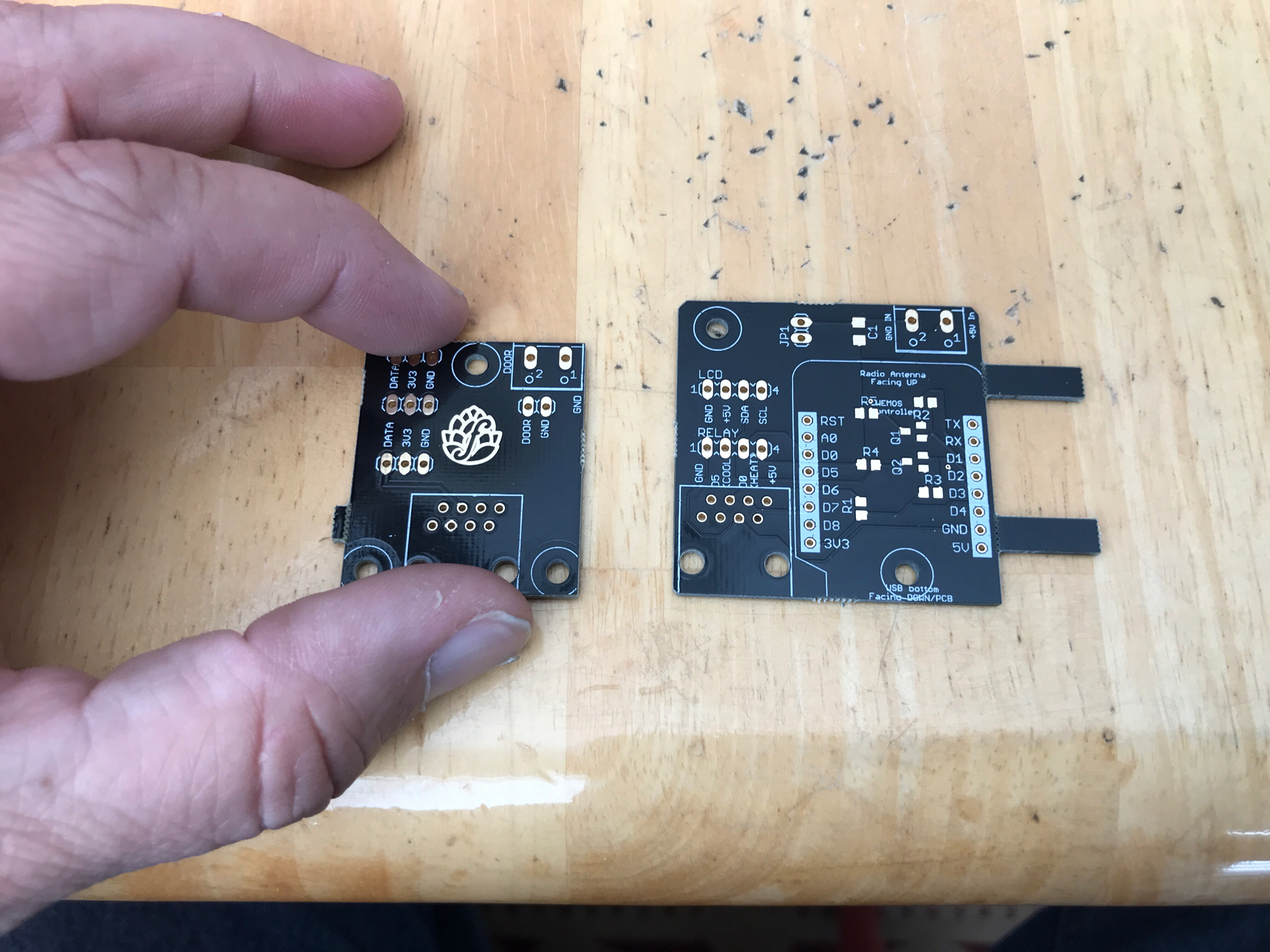
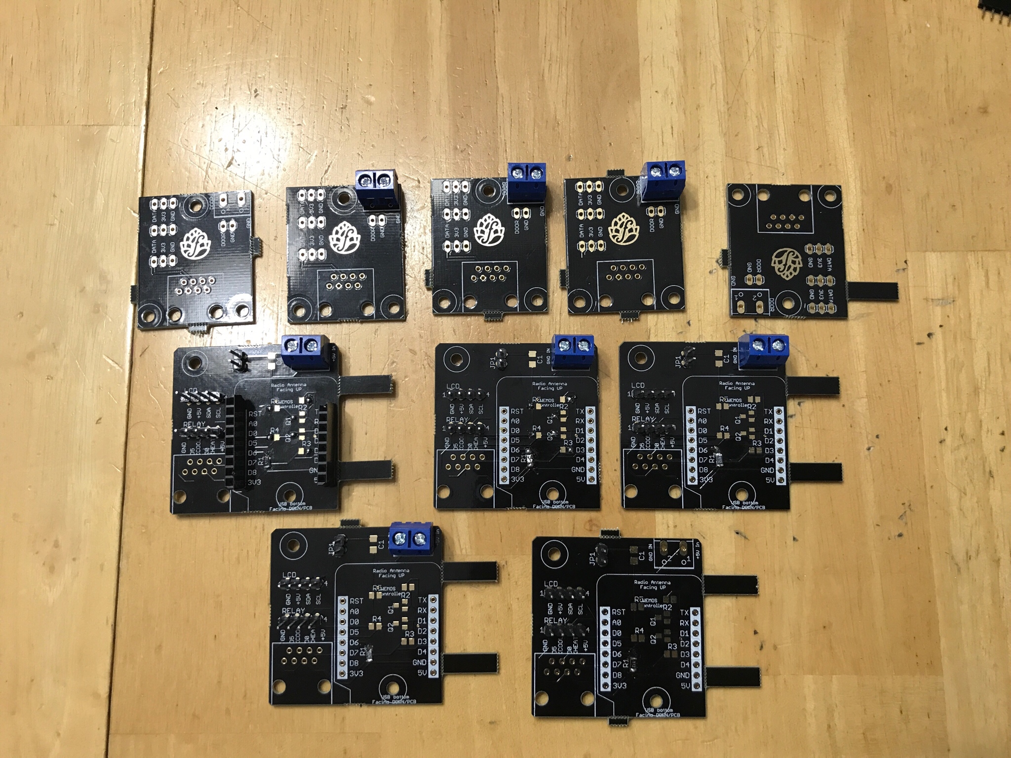
IMG_0065.JPG


You know? I knew this stuff was small, but %#@!
 
I found it a lot easier to solder on the SMD components first before anything else.
Hard to tell but are the Mosfets and resistors contacting both pads? Looks like they are soldered on one side of the pad and not completing the circuit.
 
I found it a lot easier to solder on the SMD components first before anything else.
Hard to tell but are the Mosfets and resistors contacting both pads? Looks like they are soldered on one side of the pad and not completing the circuit.

I’m still waiting on the mosfets and 10k resistors. Freaking China! I only put in the 4.7k resistors at R1, male pins, 5mm screws, and the pair of female pins....and practiced soldering.
 
I’m still waiting on the mosfets and 10k resistors. Freaking China! I only put in the 4.7k resistors at R1, male pins, 5mm screws, and the pair of female pins....and practiced soldering.
Best trick I found was to use more flux than you think you need and move the smd around with a solder tool kit
soldering-aid-kit-6-piece-12-diffrent-tools.jpg
 
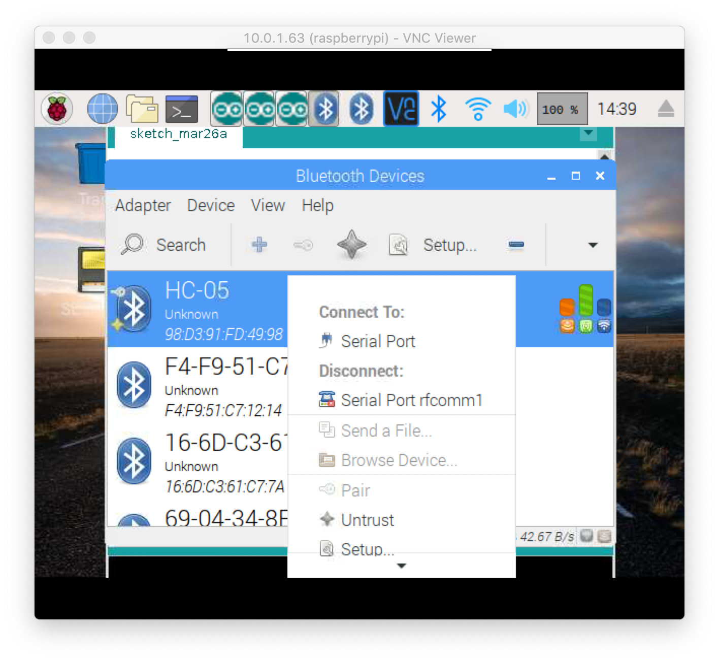
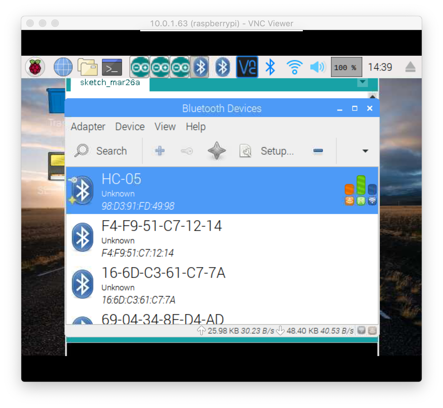
New adventure working on getting a HC-05 set up for bluetooth connectivity to the Pi. I've been following day_trippr's documentation on configuring bluetooth modules, and I have managed to get the HC-05 paired with the Pi.
Screen Shot 2019-03-26 at 2.39.34 PM.png

And after this I started Manual (Advanced) set up of a controller in Fermentrack to be able to specify the serial port for the module. I right clicked the paired module in the Pi settings and it says 'rfcomm1' .

Screen Shot 2019-03-26 at 2.39.42 PM.png


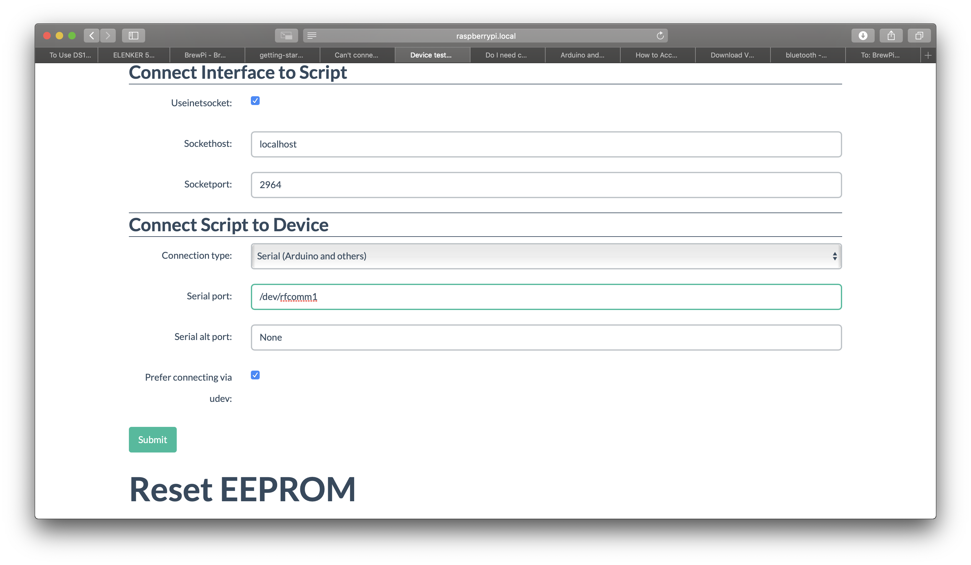
Is this what I enter in the field in Fermentrack that asks for the serial port?

Screen Shot 2019-03-26 at 2.40.46 PM.png

Because I have done this and the Uno controller is not connecting. Works fine over USB still, just not bluetooth. Am I doing this right, or am I missing something?
 
It isn’t likely related to your issue, but you’ll probably want to untick “prefer connecting via udev”.

Related to your issue, if you open a terminal and run this command what do you see?

ls -la /dev | grep rfcomm
 
It isn’t likely related to your issue, but you’ll probably want to untick “prefer connecting via udev”.

Related to your issue, if you open a terminal and run this command what do you see?

ls -la /dev | grep rfcomm

That command doesn't seem to do anything I can see. Just returns to a new line with no text displayed.
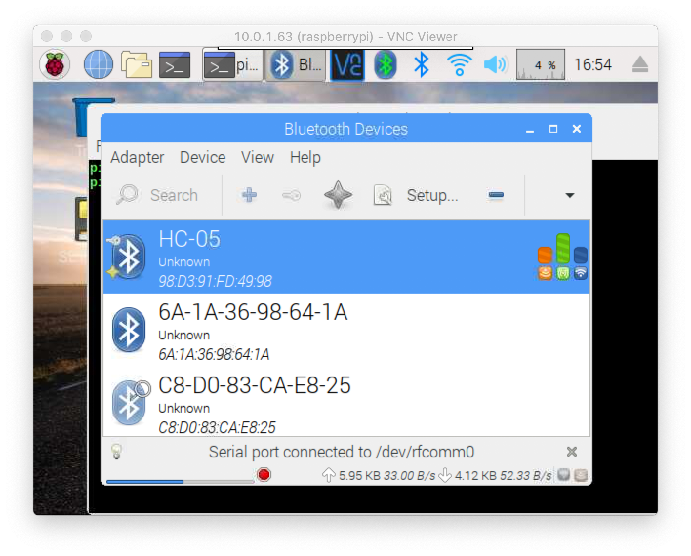
 
Screen Shot 2019-03-26 at 4.54.10 PM.png
I selected a setting to connect to serial port, and now it says connected. Does this look right? Also, it says /dev/rfcomm0 now. I tried re-adding the controller with that instead of rfcomm1 and it still doesn't work.
 
That gui indicates you have successfully connected to the HC-05 on /dev/refcomm0. If this was a BrewPi installation you'd edit /home/brewpi/settings/config.cfg to set port = /dev/rfcomm0 and once the gui is Started should connect the application to the device...

Cheers!
 
View attachment 619267 I selected a setting to connect to serial port, and now it says connected. Does this look right? Also, it says /dev/rfcomm0 now. I tried re-adding the controller with that instead of rfcomm1 and it still doesn't work.

In line with @day_trippr 's note, if you recreate the device with serial port /dev/rfcomm0 then it should work. Just make sure you untick "prefer connecting via udev"
 
Should I first flash the controller using the USB, then unplug and used advance set up with input of the serial port?

You have to flash via USB, so if BrewPi firmware isn’t already flashed to the arduino then you need to use USB to flash it. Once the firmware is flashed, you should be able to then set it up via the advanced workflow as you were just attempting to do.
 
In line with @day_trippr 's note, if you recreate the device with serial port /dev/rfcomm0 then it should work. Just make sure you untick "prefer connecting via udev"

It's weird, every time I untick "prefer connecting via udev" and click Submit, when I leave the manage page and return it re-ticks it. It still keeps my input of the serial port as /dev/rfcomm0.
 
It's weird, every time I untick "prefer connecting via udev" and click Submit, when I leave the manage page and return it re-ticks it. It still keeps my input of the serial port as /dev/rfcomm0.

That sounds like it might be a bug... I’ll take a look tonight.

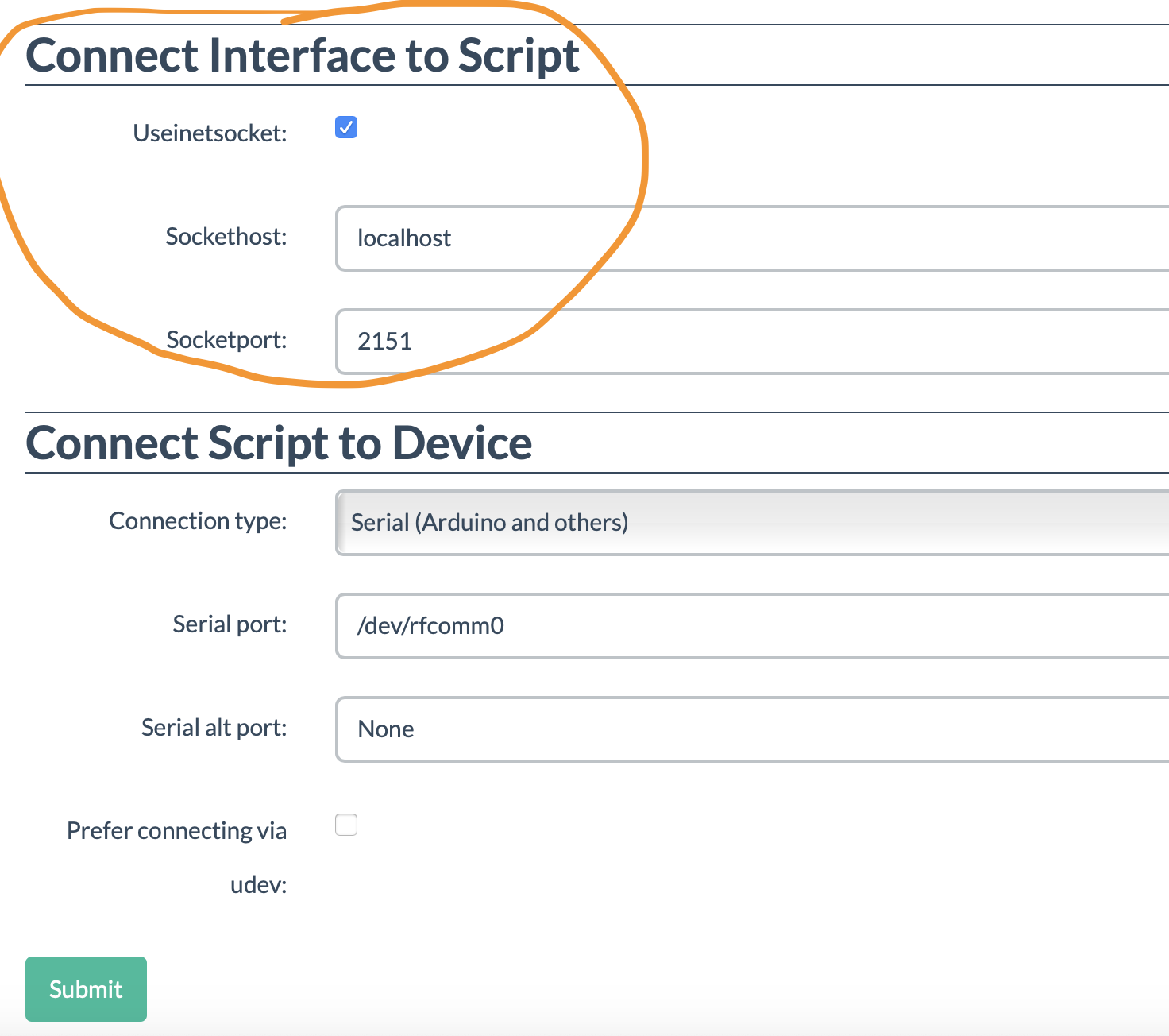
Also, is there anything I need to change in the "Connect Interface To Script" section?

View attachment 619340

No - that bit doesn’t manage anything that would impact the connection to the actual controller.
 
There are some differences in BT management in Stretch warranting some changes to @day_trippr's original instructions. I've put them here.
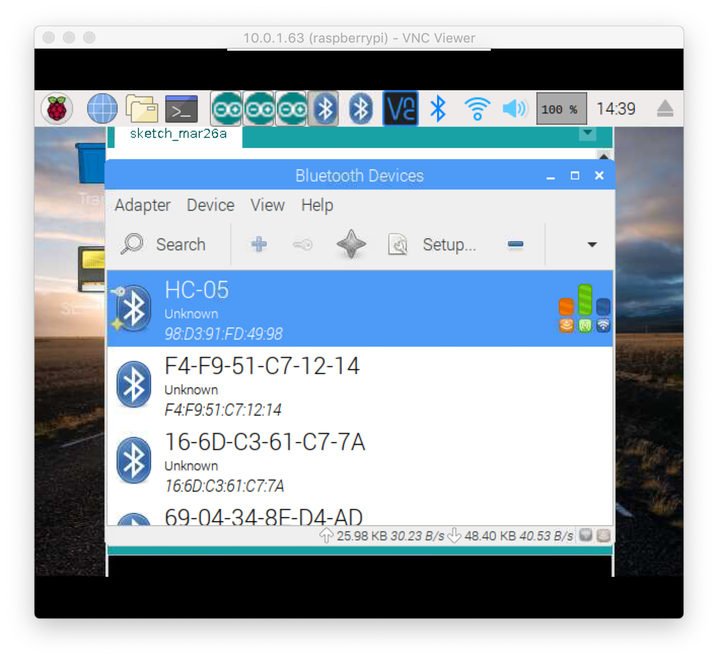
It looks like I have managed to get my HC-05 connected to the PI from the graphical Bluetooth Manager in the OS. Do you think I should follow the steps you list in that link, or have I already essentially done this?

Screen Shot 2019-03-26 at 2.39.34 PM.png


Seems like it is connected, although still not sure why Fermentrack cannot connect to the controller using the modules serial port.
 
Back
Top