You are using an out of date browser. It may not display this or other websites correctly.
You should upgrade or use an alternative browser.
You should upgrade or use an alternative browser.
Long Journey into E-brewing.
- Thread starter mendozer
- Start date

Help Support Homebrew Talk:
This site may earn a commission from merchant affiliate
links, including eBay, Amazon, and others.
These guys can be a little pricey, but seem to meet your requirements.
http://www.littelfuse.com/products/.../electrical-power-distribution-blocks/ls.aspx
http://www.littelfuse.com/products/.../electrical-power-distribution-blocks/ls.aspx
mendozer
Well-Known Member
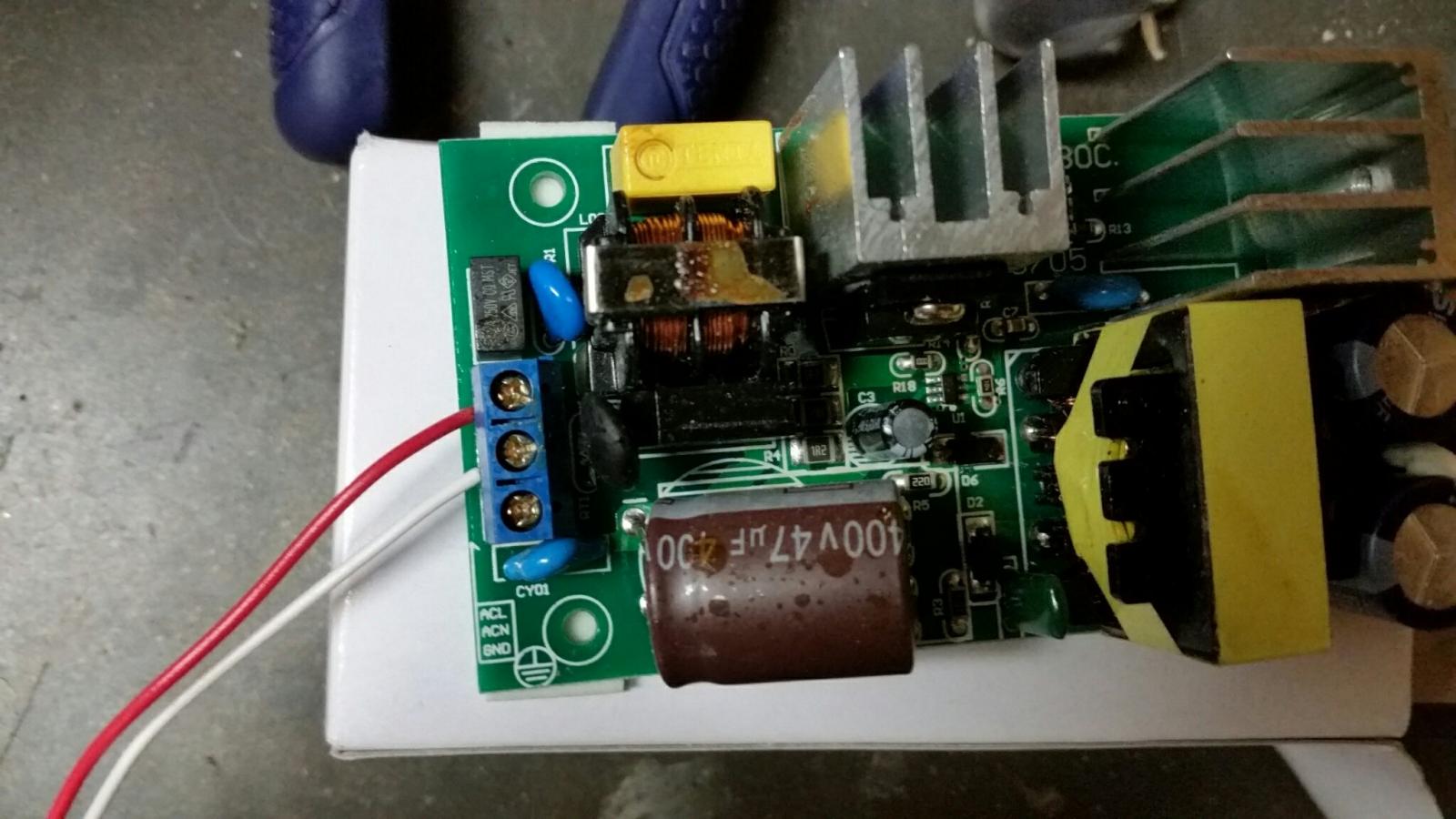
Does this seem right for the power module? I don't know whether to trust the symbols for connections or my gut of hot/white.
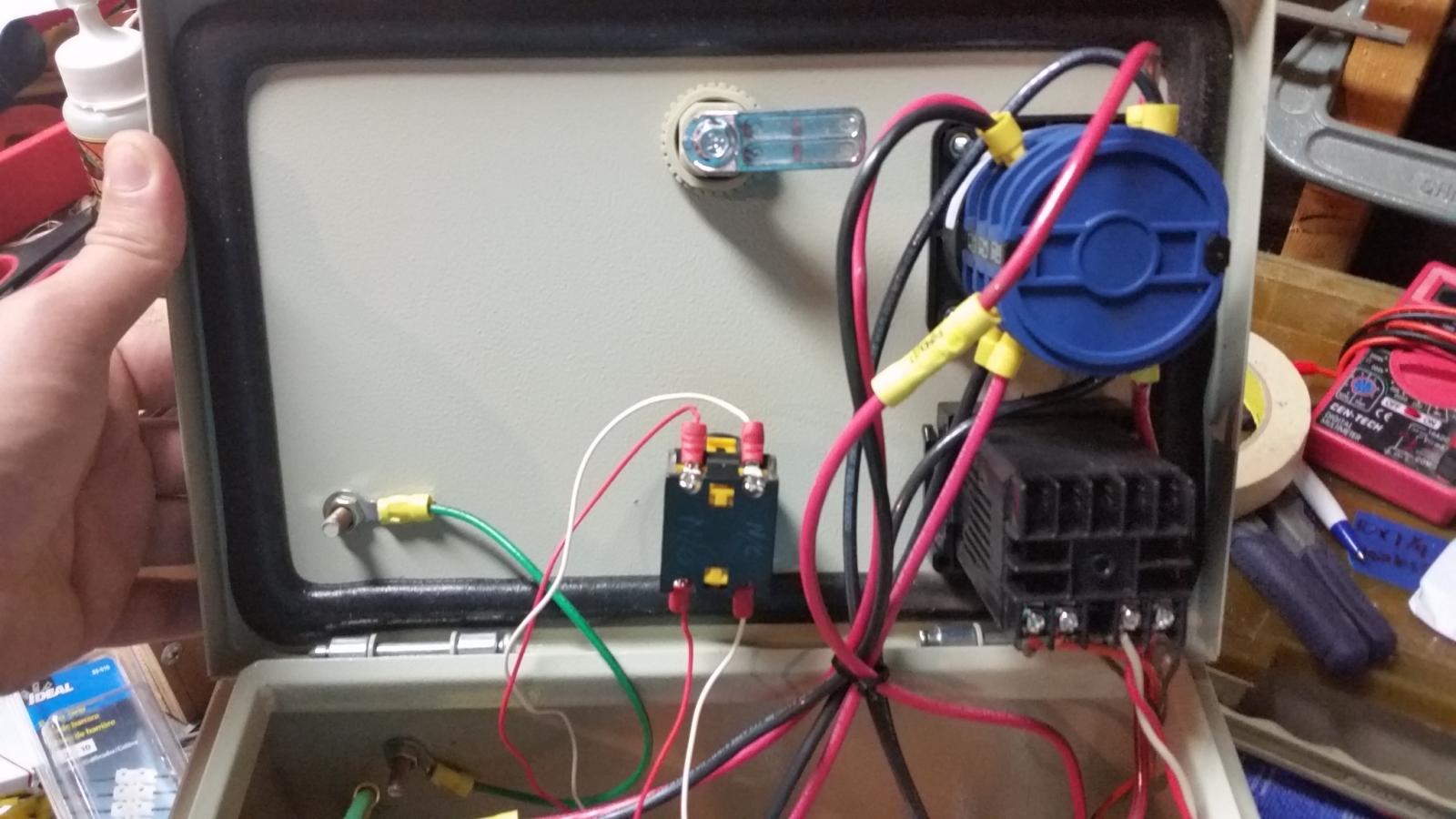
Also, that rotary switch. It's not sepcified which wire to what terminal.
There's a N/O half and N/C half. Using two conductor 20 awg wire red/white.
Couldn't find a diagram for this switch.

Also, that rotary switch. It's not sepcified which wire to what terminal.
There's a N/O half and N/C half. Using two conductor 20 awg wire red/white.
Couldn't find a diagram for this switch.


Does this seem right for the power module? I don't know whether to trust the symbols for connections or my gut of hot/white.
Also, that rotary switch. It's not sepcified which wire to what terminal.
There's a N/O half and N/C half. Using two conductor 20 awg wire red/white.
Couldn't find a diagram for this switch.
Power module looks ok, except you need to connect a ground wire to the AC input terminal block.
I assume you are asking about the switch that controls the power module. That switch needs to have two NO blocks to work. One hot goes thru one of the NO blocks and the other hot goes thru the other NO block. If you're using the Auber switch, you can get extra switch blocks if you don't already have the correct ones.
Brew on

mendozer
Well-Known Member
OK So I used my meter to test resistance of the blocks.
11 and 12 are connected and 23 and 24 are. So I wired red to 11/12 and white to 23/24. I guess it doesn't really matter which one is which, as long as one position is off and one is on once it's all hooked up.
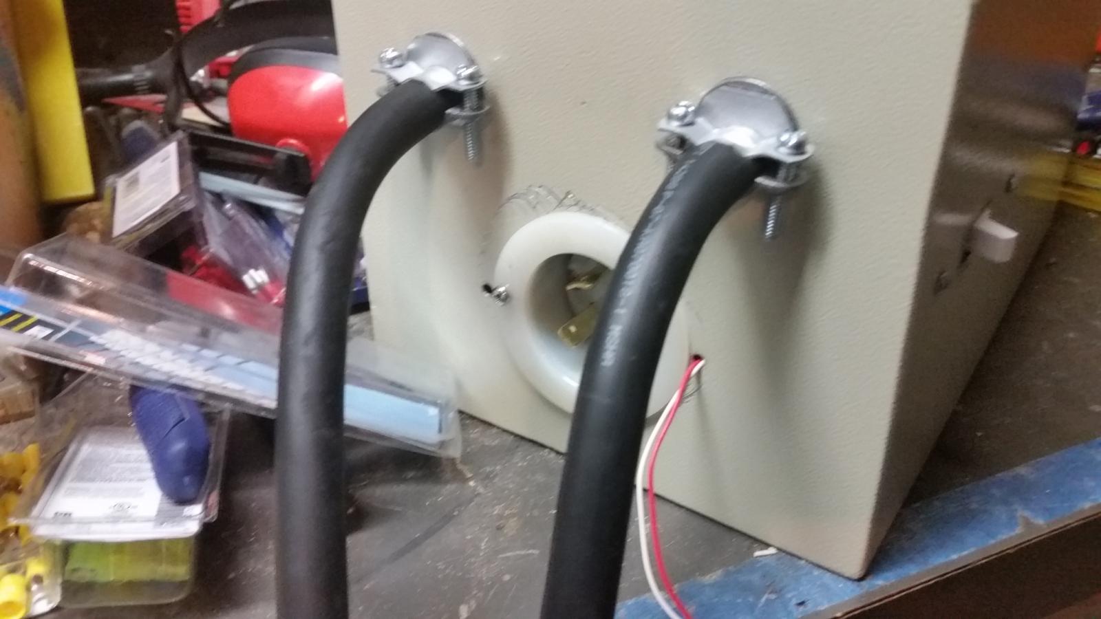
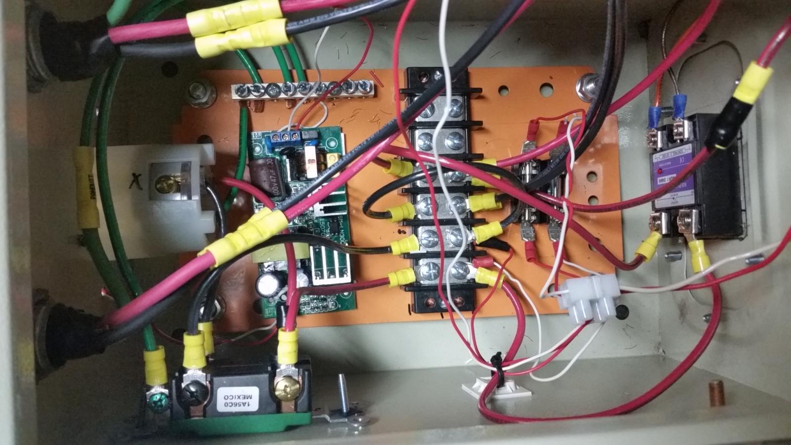
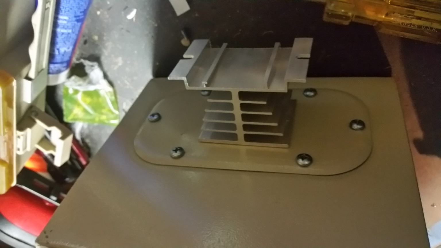
I finished it tonight and here are some final pics. Mounted the leviton switch to the side. It was tough working in the small box. Hopefully nothing breaks because I don't want to fiddle with anything in there! I wonder how long that AC/DC converter will last. I have 20 gauge for all the low voltage stuff except for 16 awg wired onto the auber controller. My electrician buddy put it on there. But since it's after the 2 amp fuses, who cares.
I still am unsure about the white wire in the spa panel. Does that stay or go?


mendozer
Well-Known Member
Power module looks ok, except you need to connect a ground wire to the AC input terminal block.
I assume you are asking about the switch that controls the power module. That switch needs to have two NO blocks to work. One hot goes thru one of the NO blocks and the other hot goes thru the other NO block. If you're using the Auber switch, you can get extra switch blocks if you don't already have the correct ones.
Brew on
Just saw this after my last post. If I need two NO blocks, why not get the SW4?
http://www.auberins.com/index.php?main_page=product_info&cPath=7_32&products_id=241

$7.79 ($7.79 / Count)
Craft A Brew - LalBrew Voss™ - Kveik Ale Yeast - For Craft Lagers - Ingredients for Home Brewing - Beer Making Supplies - (1 Pack)
Craft a Brew

$53.24
1pc Hose Barb/MFL 1.5" Tri Clamp to Ball Lock Post Liquid Gas Homebrew Kegging Fermentation Parts Brewer Hardware SUS304(Liquid Hose Barb)
Guangshui Weilu You Trading Co., Ltd

$27.29 ($13.64 / Count)
$41.99 ($21.00 / Count)
2 Pack 1 Gallon Large Fermentation Jars with 3 Airlocks and 2 SCREW Lids(100% Airtight Heavy Duty Lid w Silicone) - Wide Mouth Glass Jars w Scale Mark - Pickle Jars for Sauerkraut, Sourdough Starter
Qianfenie Direct

$53.24
1pc Hose Barb/MFL 1.5" Tri Clamp to Ball Lock Post Liquid Gas Homebrew Kegging Fermentation Parts Brewer Hardware SUS304(Liquid MFL)
yunchengshiyanhuqucuichendianzishangwuyouxiangongsi

$58.16
HUIZHUGS Brewing Equipment Keg Ball Lock Faucet 30cm Reinforced Silicone Hose Secondary Fermentation Homebrew Kegging Brewing Equipment
xiangshuizhenzhanglingfengshop

$22.00 ($623.23 / Ounce)
AMZLMPKNTW Ball Lock Sample Faucet 30cm Reinforced Silicone Hose Secondary Fermentation Homebrew Kegging joyful
无为中南商贸有限公司

$719.00
$799.00
EdgeStar KC2000TWIN Full Size Dual Tap Kegerator & Draft Beer Dispenser - Black
Amazon.com

$39.22 ($39.22 / Count)
Brewer's Best Home Brew Beer Ingredient Kit - 5 Gallon (Mexican Cerveza)
Amazon.com

$20.94
$29.99
The Brew Your Own Big Book of Clone Recipes: Featuring 300 Homebrew Recipes from Your Favorite Breweries
Amazon.com

$10.99 ($31.16 / Ounce)
Hornindal Kveik Yeast for Homebrewing - Mead, Cider, Wine, Beer - 10g Packet - Saccharomyces Cerevisiae - Sold by Shadowhive.com
Shadowhive

$176.97
1pc Commercial Keg Manifold 2" Tri Clamp,Ball Lock Tapping Head,Pressure Gauge/Adjustable PRV for Kegging,Fermentation Control
hanhanbaihuoxiaoshoudian
Just saw this after my last post. If I need two NO blocks, why not get the SW4?
http://www.auberins.com/index.php?main_page=product_info&cPath=7_32&products_id=241
The SW4 will work fine. I just called out lighted switches in the design cause lots of folks like to use them. The SW1 has two NO blocks, and the SW16 can be purchased either with 2 NO or 1 NO & 1 NC.
I believe you can just leave the white wire in the spa panel the way it is.
Brew on

mendozer
Well-Known Member
Got it. Ordered the SW4 today. I rechecked the blocks and at any given time, one's open and one's closed on mine. I didn't fully understand switches when I ordered that. I think I was set on using 120 for it at the time, which would have worked, but now using 220 all around I need two NO. I can't wait until it comes. Very exciting. I am a little worried about it all when I plug it in. I mean for a first timer who wouldn't be?
mendozer
Well-Known Member
OK I FINALLY got around to testing my elements today. I haven't brewed in forever. But when I hooked everything up...nothing.
I used my multimeter for continuity testing. Everything from outlet to SSR is fine. But terminals 1/2 are not continuous. I have no idea why. thoughts?
I used my multimeter for continuity testing. Everything from outlet to SSR is fine. But terminals 1/2 are not continuous. I have no idea why. thoughts?
augiedoggy
Well-Known Member
OK I FINALLY got around to testing my elements today. I haven't brewed in forever. But when I hooked everything up...nothing.
I used my multimeter for continuity testing. Everything from outlet to SSR is fine. But terminals 1/2 are not continuous. I have no idea why. thoughts?
? you cant test ssr switches without a load connected to them... also terminals 1 and 2 wont have continuity until the ssr is activated by the pid and closes the relay.
mendozer
Well-Known Member
I'll look up how to test ssrs when I get home. I noticed that continuity didn't change when I switched my element selector switch. My ssvr controller is supposed to be pushed in then rotated for power.
I'll look up how to test ssrs when I get home. I noticed that continuity didn't change when I switched my element selector switch. My ssvr controller is supposed to be pushed in then rotated for power.
One easy way is to connect 120V light bulb(s) between terminals 1 & 2 of the SSR or SSVR. One bulb for 120V panel output, two bulbs in series for 240V output.
Another option is just to test using your elements. Make sure they are submersed in an adequate amount of water before testing.
Brew on

mendozer
Well-Known Member
So leave my panel connected the way it is, but also splice in two light bulbs between terminals 1 and 2 of the SSR? I'll have to get some sockets and connector clips. From my understanding, my SSVR controller, the auber one, should be the one that turns the SSVR on. However, this controller never turns on. I push and nothing, turn the dial and nothing. So could the problem lie in how this is wired?
So leave my panel connected the way it is, but also splice in two light bulbs between terminals 1 and 2 of the SSR? I'll have to get some sockets and connector clips. From my understanding, my SSVR controller, the auber one, should be the one that turns the SSVR on. However, this controller never turns on. I push and nothing, turn the dial and nothing. So could the problem lie in how this is wired?
Yes.
I see that in the photo you don't have a temp sensor connected to the EZBoil. The EZBoil will not trigger the SSR without a temp sensor connected. In this case the top display should be alternating between "orAL" and "932" (according to the manual.)
Brew on

mendozer
Well-Known Member
it's the fuses! Light bulb test was fine. Then I looked at resistance between both ends of the fuses. They're both blown. I do recall seeing my lights above flicker as soon as I switched the control panel on (different breaker though).
I have the Cooper Bussman AGC-2-RP uses 1/4" x 1 1/4". I was sure these were what I wanted. Am I incorrect?
DSPR1 output is 12VDC, 80 mA
I have the Cooper Bussman AGC-2-RP uses 1/4" x 1 1/4". I was sure these were what I wanted. Am I incorrect?
DSPR1 output is 12VDC, 80 mA
mendozer
Well-Known Member
I just noticed something looking back at my wiring diagram on page 5. I don't have the DSPR110, just the DSPR1. The wiring diagram listed here below is from the manual.
I have (i think) the SSR and AC wires backwards. That could make my fuses blow right?
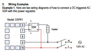
I have (i think) the SSR and AC wires backwards. That could make my fuses blow right?

mendozer
Well-Known Member
ok it was backwards. I replaced the fuses, swapped wires, then tested it. It actually turned on for a few seconds while the DSPR1 was blinking at 50%. But it shut off after that. Then the standby light would be on. Every time I pushed the button thereafter to test it, the screen would light up red (like the numerical lights) then shut back off.
ok it was backwards. I replaced the fuses, swapped wires, then tested it. It actually turned on for a few seconds while the DSPR1 was blinking at 50%. But it shut off after that. Then the standby light would be on. Every time I pushed the button thereafter to test it, the screen would light up red (like the numerical lights) then shut back off.
If you mixed up the AC power and SSR control output wires on the DSPR1, you could have damaged or destroyed the DSPR unit. The current surge that blew the fuses could not have been good for the DSPR.
Brew on

mendozer
Well-Known Member
Kane at Auber thinks the transformer inside could be fried. I'll have to send it in for repair. I'll test it tonight with a separate power source (the 120V kit I made to test the SSR last night should suffice).
I have a solid 240V at the end of the fuse before it heads into the controller though.
I have a solid 240V at the end of the fuse before it heads into the controller though.
dang it. I emailed Auber to see what they have to say as well. The fuse wouldn't protect the unit? Isn't that the whole point of them?
Not really. Fuses are intended to keep the wires from getting too hot, and starting a fire, in the event of a short downstream of the fuse. Protecting low voltage inputs/outputs from being accidentally connected to mains voltage is a whole different matter. It's possible, but takes a whole lot more than a simple fuse (for example, most quality multimeters have input protection built in.)
Brew on

Well, guess I'm not brewing this weekend. Or if I need to, I can resort to gas and somehow shield my silicone gaskets for the triclamps.
"Need to" haha! Love it! [emoji482]
mendozer
Well-Known Member
OK so got my Auber piece back repaired (not now, back in March) and FINALLY ran a test for proper function. I've been swamped with home projects and haven't brewed in seemingly eons.
But with ambient temp of 70, with water from the hose at 68, I got 4.5 gallons up to strike temp of 162 in 14 minutes. This is comparable to 45-55 minutes using propane depending on conditions. This was 100% control. Knowing I just shaved off an hour off my brew day for heating initial strike water AND getting mash out to boil faster was all worth it.
Now for the next brew....
Similar threads
- Replies
- 20
- Views
- 1K
- Replies
- 14
- Views
- 3K
Latest posts
-
-
Factors affecting Water Chemistry Calculations (Oh no, not again!)
- Latest: Unicorn_Platypus
-
-
-
-


![Craft A Brew - Safale BE-256 Yeast - Fermentis - Belgian Ale Dry Yeast - For Belgian & Strong Ales - Ingredients for Home Brewing - Beer Making Supplies - [3 Pack]](https://m.media-amazon.com/images/I/51bcKEwQmWL._SL500_.jpg)


