Long Journey into E-brewing.

Homebrew Talk - Beer, Wine, Mead, & Cider Brewing Discussion Forum

Help Support Homebrew Talk - Beer, Wine, Mead, & Cider Brewing Discussion Forum:

This site may earn a commission from merchant affiliate links, including eBay, Amazon, and others.

mendozer

Well-Known Member
Joined
Nov 15, 2009
Messages
766
Reaction score
19
Location
Seattle
I've been trying to get into this for a long time with it keep getting knocked off the project list. I finally got all my components together and am putting it to use!

Goal: CP to control two elements, one at a time, and one pump. Simple, no frills repeatable controls.

Existing equipment:
8 gallon stock pot, 15 gallon keggle, 48 qt mash tun cooler, Great Breweh (Topsflo) 12 VDC pump with AC adapter.

New Equipment:
On that screenshot


I started on this today and while at Lowe's picking up more things, the guy in electrical confused the crap out of me. He was saying that I needed a breaker before every device that's rated for said device. He also said that everything downstream should be matched (wire and breaker) for the upstream breaker. I was under the impression that everything downstream should be equal to OR LOWER than the breaker.

Here was my plan:

panel2.jpg


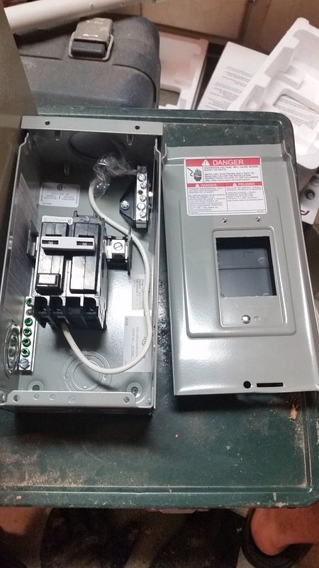
Home panel contains 50 amp breaker -->>8-3 wire-->> Spa Panel with 50 A GFCI (because 30 amp GFCI breaker itself cost way more -->> 8-3 wire-->> control panel.

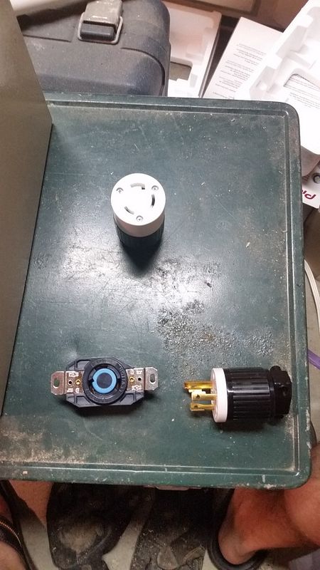
From the spa panel to the control panel is a two-male ended 10/4 cored with L6-30 male plugs on it. This is my extension cord if you will.

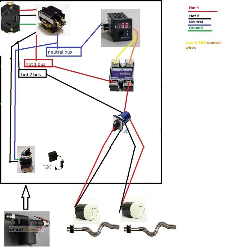
Control panel: input comes from the L6-30 receptacle > then goes into the 240 contactor with 120V coil > this provides power to the pump switch itself which is then going to the AC adapter which then goes to the pump AND to the SSVR and power meter which goes through the changeover switch into the element which is hardwired from the changeover to the female plug.

All the element stuff is with 10/4 wire, the pump with 14 gauge.


Notes: My elements are 5500W, so at peak it draws 23 amps, hence the 40 A SSVR for protection. I figure that a 40 A powered element under a 50 A GFCI is fine, yet the guy tells me I need a 40 A breaker in case more amperage finds it's way to the element. But I don't get it. It can only draw 23!!! no more will be sucked from it.
Also, for my pump he said to put a smaller breaker (like say 15 amp) before the pump. But again if it only draws 2 amps at 12 VDC (which will be downstream of the 120V AC adapter)...IDK now I'm confused.

My electrician buddy who helped me today said those breakers weren't needed, but he also said the contactor wasn't needed (the lowes guy didn't even know what a contactor was). I thought it was. How else will I get 4 wire from 3?

I feel like I'm missing a big "something" here. Can anyone help?

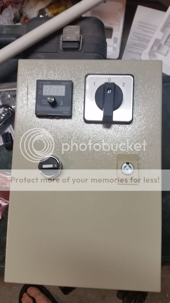
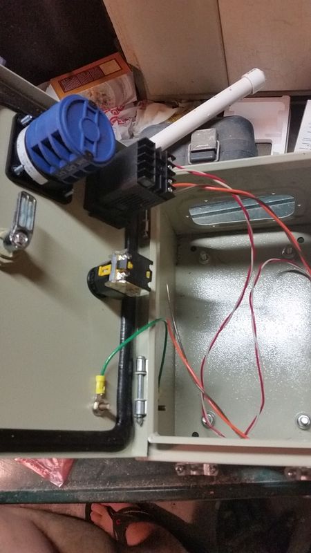
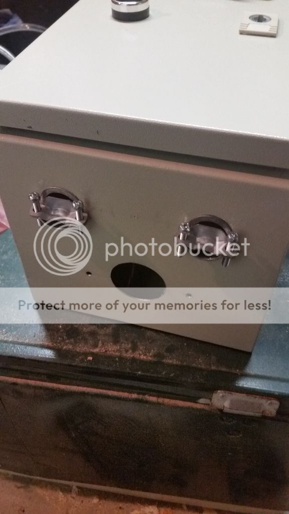
Here's what I have so far:
20160710_175227.jpg

20160710_175314.jpg

20160710_175412.jpg

20160710_175233.jpg

20160710_175329.jpg


Capture.jpg
 
I see a few issues.

#8 NM cable is not rated for 50A. You do not specify what type of wire you are using (I'm assuming Romex). A 40A breaker in your main panel will solve that.

Looks like you have a few 50A breakers then a 30A cord/receptacle. You need to protect those 30A devices and #10 wire at less than 50A. A breaker or fuses protects the wire and devices downstream. If you jump from 50A to 30A, you need to fuse for the wire/devices used. Likewise from 30A to 15A and so on...

NEVER build a cord with two male ends. They make flanged inlets to connect female cord ends. If you think about it a bit, I'm sure you can imagine the danger a hot male cord end could be.

I think you're missing some of the fundamentals. You should browse some wiring diagrams around here for some ideas. It is pretty easy to modify a diagram to fit your specific needs.
 
Also, you can't get a neutral bus from a three wire feed, without going thru a spa panel (or something similar.) Electricity can kill you or burn your house down. Get some help from someone who is qualified. I don't want to be cruel, but if you think a male/male extension cord is a good idea for 240V, you are not qualified to be doing this on your own.

Brew on :mug:
 
I see a few issues.

#8 NM cable is not rated for 50A. You do not specify what type of wire you are using (I'm assuming Romex). A 40A breaker in your main panel will solve that.

Looks like you have a few 50A breakers then a 30A cord/receptacle. You need to protect those 30A devices and #10 wire at less than 50A. A breaker or fuses protects the wire and devices downstream. If you jump from 50A to 30A, you need to fuse for the wire/devices used. Likewise from 30A to 15A and so on...

NEVER build a cord with two male ends. They make flanged inlets to connect female cord ends. If you think about it a bit, I'm sure you can imagine the danger a hot male cord end could be.

I think you're missing some of the fundamentals. You should browse some wiring diagrams around here for some ideas. It is pretty easy to modify a diagram to fit your specific needs.

OK so a 40 amp breaker in the house panel, will that complicate my 50A GFCI in the spa panel? Or as long as the main source (house panel) is limited to 40 then I'm good.

As far as fuses, I did see those on wiring diagrams but wasn't sure how they go. So let's say my contactor out goes to the 110 AC adapter rated at 2 A, I put a 2A fuse between the two?

As far as the extension cord goes, that's just for setup. Nothing is on while I'm plugging it in. Then when the brew stand is ready to go, I flip the switch at the GFCI to power the whole system. I went this route because for whatever reason, the recessed male flanges are like 3x the cost of the female.
 
Also, you can't get a neutral bus from a three wire feed, without going thru a spa panel (or something similar.) Electricity can kill you or burn your house down. Get some help from someone who is qualified. I don't want to be cruel, but if you think a male/male extension cord is a good idea for 240V, you are not qualified to be doing this on your own.

Brew on :mug:

Again, I'm working with an electrician, but FWIW he's a low voltage controls guy. I mentioned getting 4 wire out of the contactor and he just said "sure ok if that's what you want".

So he can't answer (or the guy at Lowe's couldn't either) my original question. How can I get all 4 that handle 40 amp? I see 8/3 and 8/2 at the store, no 8/4. There's 6/4 online..?

I'm trying to gather information and I don't want to do it wrong of course. That's why I'm asking the experienced people.

I'm not trying to be stubborn and I'm open to criticism. If something doesn't look right, rip it up and I won't be offended.
 
Last edited:
https://www.amazon.com/dp/B00RE11C2I/?tag=skimlinks_replacement-20

If I put this in there, then I don't need 4 wire right? This takes the 240V and outputs 12VDC 3A for my pump. PLLEEEASE say yes so I don't have to redesign the whole damned thing.

Also regarding wiring diagrams, I have only seen PID ones. If anyone wants to draw one up for me I'd greatly appreciate it. I am a visual learner so if I see where things go (like to the terminals) then I'm more confident with this.
 
Last edited by a moderator:
As far as the extension cord goes, that's just for setup. Nothing is on while I'm plugging it in. Then when the brew stand is ready to go, I flip the switch at the GFCI to power the whole system. I went this route because for whatever reason, the recessed male flanges are like 3x the cost of the female.

Are you really trying to justify having a plug with a live male end? With all due respect, this is absolutely unacceptable from a safety perspective.
 
OK I'll change the plug. I did already put the female outlet on the box so I'll connect the male end first, then put a female end on the other side to the spa panel.

Changes to be made after some of your comments:
30A breaker in the house panel (you said 40, but 30 is more than enough). This will render my 50 amp GFCI spa panel into just a GFCI safety measure (and I guess technically make it that only 30A runs through it).

add a female end to the extension cord from spa to control panels

Add fuses to the plan before lower amp devices (like my pump switch)

One thing I can't find is the incoming amp rating for my DSPR1 (I emailed Auber too), and the AC/DC module. Unless this doesn't matter since it as an output of XX Amps.

If I use the AC/DC module, I'm hypothesizing that I can use 10/4 SOOW all around yet not really need the neutral for the 120 v circuit (since the pump was the only 120 requirement).

I've checked all my devices and they're all rated appropriately to my understanding.

I attached a schematic if anyone can help me with wiring. It will help me understand where fuses go (and what amp rating it needs to be) and the overall line in and line out.

20160711_101157.jpg
 
I don't really know what you mean by the incoming amp rating for the DSPR1. You could hook it to a 1000 amp service but it will probably only draw a couple of watts when running. You supply line voltage to it, and it turns the SSR on and off. There really isn't any current running through it besides a few hundred miliamps.
 
I don't really know what you mean by the incoming amp rating for the DSPR1. You could hook it to a 1000 amp service but it will probably only draw a couple of watts when running. You supply line voltage to it, and it turns the SSR on and off. There really isn't any current running through it besides a few hundred miliamps.


OK got it. I was assuming every device drawing whatever amps (rated for the appropriate voltage) needs a fuse or breaker upstream for it's amp rating.
 
ok. Don't laugh but here's my attempt after studying P-J diagrams.

@Jeffmeh, I didn't see your response till posting this. wouldn't I want fuses for the downstream device, like in my pic?

wiring2.jpg
 
ok. Don't laugh but here's my attempt after studying P-J diagrams.

@Jeffmeh, I didn't see your response till posting this. wouldn't I want fuses for the downstream device, like in my pic?

IMO, fusing each individual component is overkill. What I described (citing Kal) is perfectly safe, practical, and in wide use.
 
ok so the one 7 amp fuse in one line (say Hot 1) sets the max amperage from then on at 7 amps. This goes into the pump switch (rated at 10A max) and then to the AC/DC power module (rated 3 amp), then into the Topsflo pump.

But (and excuse me if this is a dumb question) wouldn't the 7 amp fuse not protect the AC/DC converter rated at 3?
 
forgot to mention the plan to change the type of plugs too. 10/4 coming in will require me to switch L6-30 to L14-30. But at the elements I need L6-30 still.

I do need neutral wiring for this AC/DC converter from what I'm gathering.

plugs layout.jpg
 
ok so the one 7 amp fuse in one line (say Hot 1) sets the max amperage from then on at 7 amps. This goes into the pump switch (rated at 10A max) and then to the AC/DC power module (rated 3 amp), then into the Topsflo pump.

But (and excuse me if this is a dumb question) wouldn't the 7 amp fuse not protect the AC/DC converter rated at 3?

When fusing 240V circuits, you have to fuse both line 1 and line 2, since both can supply power. When fusing 120V circuits, you only have to fuse the hot line. You don't need to fuse neutral, as it cannot supply any power. Since you will have only 240V circuit branches in your panel, you need to have a fuse for each hot line.

Your AC/DC converter is rated at 36W max output. If we assume it is only 50% efficient (it's probably 80% - 95% efficient) then the input power would be max 72W. At 240V, 72W is only 72 / 240 = 0.3 A. You could use 1A or 2A fuses for your pump power supply. The DSPR1 is probably rate for less than 5W power draw (for some reason the power requirement of the DSPR1 is not specified, but the DSPR110 is rated less than 5W), so can also use 1A fuses. With 1A or 2A fuses you can use finer wire to connect up the low current circuit branches, which will make wiring easier.

Brew on :mug:
 
ok. Don't laugh but here's my attempt after studying P-J diagrams.

@Jeffmeh, I didn't see your response till posting this. wouldn't I want fuses for the downstream device, like in my pic?

You need a master power switch in your panel. This can either be a DPST switch rated at 30A, or a DPST 30A contactor controlled by a simple switch. You showed a picture of a contactor in your first post. Is that what you plan to use, or would you rather use a direct action switch?

Brew on :mug:
 
I took the contactor out since I figured I could supply the whole thing with 4 wire.

I'll throw in a switch with contactor OR a DPST switch, whichever is less. originally I was just going to use the spa breaker as my Emergency stop. Plus having the changeover switch in the panel, no power can go to either element if it's in the middle position. And the pump switch is an on/off also. That's why I didn't toss one in there.
 
This E stop ( 1 amp fuse before) in parallel with this contactor

Sound like a plan?

Here's a new diagram using this E stop method. The only diagram I could copy was a P-J one using a contactor in a different way so I don't know where line 2 exits the contactor. Also, this diagram used 1 Kohm resistors before the E stop switch, despite the 1 amp fuse before hand.

So this diagram's incomplete, but IDK how to finish it (if it's even right)

wiring3estop.jpg
 
this is also an option, seems cheaper and maybe easier esp since I can't find a diagram to copy which uses my hardware.
 
I can put together a drawing for your panel, now that your plan seems more complete. Take a day or two.

Brew on :mug:
 
awesome thanks! I'm going to order those extra parts off amazon tomorrow, maybe they'll go on sale for Prime day
 
I need to get either the contactor and switch OR the main switch I linked. I see that it's a 3 pole 2 position. Does that matter? I know you said double pole. What would you recommend? I like the simplicity of wiring the main switch since it's just inline with what I have.

The other parts are the L14-30 connectors instead of my L6-30s which don't allow for the 4 wire setup.

And a little heat sink. I forgot to get one of those somehow.
 
Last edited by a moderator:
hmm ok I ignored the basic switches. Didn't think they were heavy duty. I could put that on the side of my panel. OK I'll get that.
 
Unfortunately you started buying and building before asking questions. Now the help you get is split between the best thing and the compromise to use what you already have.

A couple points from things I picked up in the thread.
1. You could skip the 4-wire if you just get an AC/DC adapter that can handle 230v on the inlet side. They are pretty common.
2. You could have skipped the huge high current selector dial switch and went with a DPDT toggle with center off. This serves as an "off" disconnect and also a selector between the two elements. Both functions for $36 and more compact: http://www.westwayelectricsupply.com/3025brn-switch-tog-dp-dt-30a-120-277v-br.html The hatco brand one you linked to is cheaper but I'm not familiar with the brand.
3. I see a lot of people putting their main disconnect function before the controller (PID in most cases) but I think it's a mistake. That means that there's no way to play around with the programming without having one of the element enabled for firing. The way I do my panels is to feed the controller power when the unit is plugged in. The disconnect isolates all the high current circuitry.


my 3 position selector switch that I already have is a on-off-on. That's why I didn't think I needed the other switch. But then that stops any potential electricity from going to my ac dc adapter in my design.

and the ACDC module I have listed does accept up to 265V. I just noticed that on the board it as a ACL, ACN, GND connector. I assumed I needed neutral.
 
With the off position on your selector, you really do not need any additional switches unless you wanted to be able to shut the Auber unit off for some reason. In that case you only need a 1amp toggle.
 
OK that's what I originally thought was ok. because my ACDC module will have a switch too (fuse in front). I guess some people like having a master on/off for the whole panel. Added measure of assurance.
 
I'm not a fan of using a double throw, center off switch as a main disconnect. Every main disconnect I have ever seen is single throw, and if it is linear action (i.e. not rotary) then OFF is in the down position. I think code might have something to do with that. If you want to shut something off in a hurry, you want to slam the switch, not worry about whether you have it correctly in the center detent.

Brew on :mug:

ok cool. Let's do the Leviton switch you mentioned. Its $11 so it won't end the world.
 
I'm having trouble finding any wiring diagrams for the LW28-32A rotary changeover switch. Can you do some testing with an ohmmeter and tell me which pairs of contacts have continuity between them when the switch is in the "1" position, and which pairs have continuity in the "2" position? I think I know the answer, but I'd rather be sure before labeling them on the schematic.

Brew on :mug:
 
1/2,5/6,9/10 for 1. The others for 2. Which on the bottom it was noted (left half said 1 right half said 2)
 
I got my L4-30s in so I can get a head start wiring those in for my plugs. Any other information you want/need for the diagram?
 
I got my L4-30s in so I can get a head start wiring those in for my plugs. Any other information you want/need for the diagram?
I think I got everything. Just working on drawing up the switch wiring. Sorry I'm a little slower than planned.

Brew on :mug:
 
No sorry needed. You are doing a favor for me after all. I was just curious if you were waiting on me for something.
 
Back
Top