With the off position on your selector, you really do not need any additional switches unless you wanted to be able to shut the Auber unit off for some reason. In that case you only need a 1amp toggle.
You are using an out of date browser. It may not display this or other websites correctly.
You should upgrade or use an alternative browser.
You should upgrade or use an alternative browser.
Long Journey into E-brewing.
- Thread starter mendozer
- Start date

Help Support Homebrew Talk:
This site may earn a commission from merchant affiliate
links, including eBay, Amazon, and others.
OP
OP
mendozer
Well-Known Member
OK that's what I originally thought was ok. because my ACDC module will have a switch too (fuse in front). I guess some people like having a master on/off for the whole panel. Added measure of assurance.
I'm not a fan of using a double throw, center off switch as a main disconnect. Every main disconnect I have ever seen is single throw, and if it is linear action (i.e. not rotary) then OFF is in the down position. I think code might have something to do with that. If you want to shut something off in a hurry, you want to slam the switch, not worry about whether you have it correctly in the center detent.
Brew on
Brew on
OP
OP
mendozer
Well-Known Member
I'm not a fan of using a double throw, center off switch as a main disconnect. Every main disconnect I have ever seen is single throw, and if it is linear action (i.e. not rotary) then OFF is in the down position. I think code might have something to do with that. If you want to shut something off in a hurry, you want to slam the switch, not worry about whether you have it correctly in the center detent.
Brew on
ok cool. Let's do the Leviton switch you mentioned. Its $11 so it won't end the world.
I'm having trouble finding any wiring diagrams for the LW28-32A rotary changeover switch. Can you do some testing with an ohmmeter and tell me which pairs of contacts have continuity between them when the switch is in the "1" position, and which pairs have continuity in the "2" position? I think I know the answer, but I'd rather be sure before labeling them on the schematic.
Brew on
Brew on


$27.29 ($13.64 / Count)
$41.99 ($21.00 / Count)
2 Pack 1 Gallon Large Fermentation Jars with 3 Airlocks and 2 SCREW Lids(100% Airtight Heavy Duty Lid w Silicone) - Wide Mouth Glass Jars w Scale Mark - Pickle Jars for Sauerkraut, Sourdough Starter
Qianfenie Direct


![Craft A Brew - Safale BE-256 Yeast - Fermentis - Belgian Ale Dry Yeast - For Belgian & Strong Ales - Ingredients for Home Brewing - Beer Making Supplies - [3 Pack]](https://m.media-amazon.com/images/I/51bcKEwQmWL._SL500_.jpg)


$719.00
$799.00
EdgeStar KC2000TWIN Full Size Dual Tap Kegerator & Draft Beer Dispenser - Black
Amazon.com


$7.79 ($7.79 / Count)
Craft A Brew - LalBrew Voss™ - Kveik Ale Yeast - For Craft Lagers - Ingredients for Home Brewing - Beer Making Supplies - (1 Pack)
Craft a Brew


$10.99 ($31.16 / Ounce)
Hornindal Kveik Yeast for Homebrewing - Mead, Cider, Wine, Beer - 10g Packet - Saccharomyces Cerevisiae - Sold by Shadowhive.com
Shadowhive


$20.94
$29.99
The Brew Your Own Big Book of Clone Recipes: Featuring 300 Homebrew Recipes from Your Favorite Breweries
Amazon.com


$53.24
1pc Hose Barb/MFL 1.5" Tri Clamp to Ball Lock Post Liquid Gas Homebrew Kegging Fermentation Parts Brewer Hardware SUS304(Liquid MFL)
yunchengshiyanhuqucuichendianzishangwuyouxiangongsi


$53.24
1pc Hose Barb/MFL 1.5" Tri Clamp to Ball Lock Post Liquid Gas Homebrew Kegging Fermentation Parts Brewer Hardware SUS304(Liquid Hose Barb)
Guangshui Weilu You Trading Co., Ltd


$22.00 ($623.23 / Ounce)
AMZLMPKNTW Ball Lock Sample Faucet 30cm Reinforced Silicone Hose Secondary Fermentation Homebrew Kegging joyful
无为中南商贸有限公司


$176.97
1pc Commercial Keg Manifold 2" Tri Clamp,Ball Lock Tapping Head,Pressure Gauge/Adjustable PRV for Kegging,Fermentation Control
hanhanbaihuoxiaoshoudian


$39.22 ($39.22 / Count)
Brewer's Best Home Brew Beer Ingredient Kit - 5 Gallon (Mexican Cerveza)
Amazon.com


$58.16
HUIZHUGS Brewing Equipment Keg Ball Lock Faucet 30cm Reinforced Silicone Hose Secondary Fermentation Homebrew Kegging Brewing Equipment
xiangshuizhenzhanglingfengshop


I think I got everything. Just working on drawing up the switch wiring. Sorry I'm a little slower than planned.I got my L4-30s in so I can get a head start wiring those in for my plugs. Any other information you want/need for the diagram?
Brew on
Ok, here's the design. Let me know if you have any questions.

There is no such thing as a NEMA L4-30 Plug/Receptacle. I assume you have the 4-wire L14-30 Plugs/Receptacles. You don't need 4-wire power connections in a 240V only system. You can use them instead of the L6-30's by connecting ground to the "G" terminal, the two hots to "x" & "Y", and leaving "W" open.

Brew on
OP
OP
mendozer
Well-Known Member
oh so this whole thing is using my 3 wire. I thought I needed 4 wire, that's why I got 14-30s. you're saying connecting Hot1, Hot 2, and G to the power supply's ACL, ACN, GND is ok? It didn't have a wiring thing with it so I assumed N was neutral.
oh so this whole thing is using my 3 wire. I thought I needed 4 wire, that's why I got 14-30s. you're saying connecting Hot1, Hot 2, and G to the power supply's ACL, ACN, GND is ok? It didn't have a wiring thing with it so I assumed N was neutral.
In a 120V system, "N" would be neutral. But you said earlier the supply was rated up to 265V input. In a 240V (US) system, there is no neutral, and the power supply doesn't really care.
Brew on
OP
OP
mendozer
Well-Known Member
OK I was thinking about this earlier. Maybe the N is listed as a connection because the input ranges from 95 to 265V so maybe you can do 110 or 220 setup. I'm going to take a crack at this. I guess if it works I'll return the L14-30
OP
OP
mendozer
Well-Known Member
ok so I've been doing little by little when I have time. Using the L6-30s, I returned the L14-30s.
I made the female plugs (which go tot he elements) this way: X to black, Y to red, G to ground.
However, when I made my outlet on the wall from the breaker, the instructions said X to red, Y to black. Does it matter if I have X and Ys mismatching red and black? Not really right since they both provide 120V. Unless there's a requirement for polarity or something.
OP
OP
mendozer
Well-Known Member
ok I looked into it a bit and it seems that polarity is the red/black. BUT, does polarity matter for my applications??
I assume it's not important because in the diagram the red and black go to different terminals on the female plugs. But can you confirm this before I finalize things?
I assume it's not important because in the diagram the red and black go to different terminals on the female plugs. But can you confirm this before I finalize things?
Last edited:
ok so I've been doing little by little when I have time. Using the L6-30s, I returned the L14-30s.
I made the female plugs (which go tot he elements) this way: X to black, Y to red, G to ground.
However, when I made my outlet on the wall from the breaker, the instructions said X to red, Y to black. Does it matter if I have X and Ys mismatching red and black? Not really right since they both provide 120V. Unless there's a requirement for polarity or something.
ok I looked into it a bit and it seems that polarity is the red/black. BUT, does polarity matter for my applications??
I assume it's not important because in the diagram the red and black go to different terminals on the female plugs. But can you confirm this before I finalize things?
I did some quick (definitely not comprehensive) searching about wiring 240V outlets, and didn't find anything about a convention or code requirement for how red and black should connect to the X and Y terminals. If anyone reading this knows more, please comment. Electrically it doesn't matter. There is certainly no harm in maintaining consistency in which color wire goes to which letter terminal. I just swapped the connections in the drawing as it made the drawing cleaner.
The only potential concern would be if you tried to connect a piece of equipment with two plugs that connected the hots from the two plugs internally. I can't think of a case where doing this would make sense.
Brew on
OP
OP
mendozer
Well-Known Member
I had a delay as I had to order a fuse holder off amazon as the local stores didn't carry the snap in type for glass fuses.
I'm slowly getting things done. Here's an update from the spa panel
Wired this up (hopefully right). Feed from house panel goes through this GFCI spa panel, then to an outlet in which the wire is spliced. One way goes to the plug and the other continues out to the dangling female L6-30. The outlet is for my welder.
OP
OP
mendozer
Well-Known Member
I didn't wire that white wire in the spa panel. It came like that. Since I'm not using 120, I don't really need that from my understanding. But I also don't see it causing problems since nothing's going to the lug to get power from that white wire. So should I leave it be or take it out?
OP
OP
mendozer
Well-Known Member
ok did some more work on it today. I realized putting wire straight into terminals doesn't look very legit. Maybe I should do connectors. Here's what I thought of.
Also, thought I'd add one lug for grounding. Otherwise twist nuts for Hot 1 and 2

Also, thought I'd add one lug for grounding. Otherwise twist nuts for Hot 1 and 2
Last edited:
Personally, I wouldn't use twist nuts on high current wiring. I'd double up crimped spade or ring lugs on device terminals or terminal strips to make the branch connections.
Brew on
Brew on
OP
OP
mendozer
Well-Known Member
Personally, I wouldn't use twist nuts on high current wiring. I'd double up crimped spade or ring lugs on device terminals or terminal strips to make the branch connections.
Brew on
So you'd put one 10 gauge wire into a ring terminal...then put another ring terminal? I don't understand your statement, sorry

You can get a good feel for how to wire with terminal strips looking here: https://www.google.com/search?site=....ZJFSAFW7rlM#tbm=isch&q=terminal+strip+jumper.
Here's one pic that shows putting two lugs on a single terminal. This same method can be used on SSR terminals, switch terminals, etc.

Brew on
Here's one pic that shows putting two lugs on a single terminal. This same method can be used on SSR terminals, switch terminals, etc.
Brew on
OP
OP
mendozer
Well-Known Member
Ah I see what you meant now. Thanks
Maybe I'll do rings instead of spades. Seems more secure. Even though in theory nothing should move around.
I'd have to make sure to cut all the jumper pieces in between right? Since I want 6 separate strips or connections.
Maybe I'll do rings instead of spades. Seems more secure. Even though in theory nothing should move around.
I'd have to make sure to cut all the jumper pieces in between right? Since I want 6 separate strips or connections.
Ah I see what you meant now. Thanks
Maybe I'll do rings instead of spades. Seems more secure. Even though in theory nothing should move around.
I'd have to make sure to cut all the jumper pieces in between right? Since I want 6 separate strips or connections.
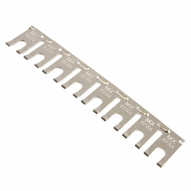
Normally you have to add the jumpers, as each pair of contacts is isolated from the pair on either side. From the linked image page, there are two common styles of jumpers.
Edit: I think you should be able to wire this design without terminal strips by using the technique of putting two wires (with crimped lugs) on the appropriate component terminals. If you need help selecting suitable terminals, I can sketch something up for you.
Jumper style 1:

Jumper style 2:
Brew on
OP
OP
mendozer
Well-Known Member
I was given a few of these by my buddy today.
http://idealind.com/us/en/products/...rips/ideal-barrier-strips/barrier-strips.aspx
They seem good for splicing but I don't see how I'll joint two wires into one port. Kinda small. I might need the above terminal strips.
http://idealind.com/us/en/products/...rips/ideal-barrier-strips/barrier-strips.aspx
They seem good for splicing but I don't see how I'll joint two wires into one port. Kinda small. I might need the above terminal strips.
Even though I added a terminal strip in my panel I ended up wiring it up with out using it at all. So you don't need terminal strips but many people use them.


Similar threads
- Replies
- 20
- Views
- 1K
- Replies
- 14
- Views
- 3K

Latest posts
-

-
 Factors affecting Water Chemistry Calculations (Oh no, not again!)
- Latest: Unicorn_Platypus
-

-

-
-