You are using an out of date browser. It may not display this or other websites correctly.
You should upgrade or use an alternative browser.
You should upgrade or use an alternative browser.
Electric Question
- Thread starter Ohio-Ed
- Start date

Help Support Homebrew Talk:
This site may earn a commission from merchant affiliate
links, including eBay, Amazon, and others.
OP
OP
- Joined
- Nov 18, 2008
- Messages
- 2,058
- Reaction score
- 25
On your diagram, where the out from 5 connects back to 14, did you just pigtail that?
I just used a short jumper wire.
egurney
Well-Known Member
- Joined
- Apr 26, 2008
- Messages
- 256
- Reaction score
- 1
Meaning that you had two wires entering at 14?I just used a short jumper wire.
Wasn't sure how many wires you could put in the terminal.
OP
OP
- Joined
- Nov 18, 2008
- Messages
- 2,058
- Reaction score
- 25
Meaning that you had two wires entering at 14?
Wasn't sure how many wires you could put in the terminal.
I used crimp on spade connectors similar to;
http://www.radioshack.com/product/index.jsp?productId=2104014
I put 2 connectors under the screw terminal on the relay socket where needed.
egurney
Well-Known Member
- Joined
- Apr 26, 2008
- Messages
- 256
- Reaction score
- 1
I guess I need to start collecting pieces. That seems like that would have been obvious if I had it in hand.I put 2 connectors under the screw terminal on the relay socket where needed.
Douglefish
Well-Known Member
- Joined
- Dec 22, 2008
- Messages
- 263
- Reaction score
- 2
Ohio-Ed,
I've noticed you are talking about have a 5500W element in both the HLT and BK and a 1500W RIMS heater? It seems like a handful of other folks on this thread are using a similar setup, but I don't quite get it.
Do you have a coil in the HLT that you are recirculating through or are you only using the RIMs?
If you do have a coil in the HLT, would you ever use both the RIMS and the "HERMS" coil?
If you do have a coil in the HLT and a RIMS, what is the driving reason for having both?
Thanks
GreenMonti - 6/4 SO Cord is rated for 45 amps (6/3 is 55).
CodeRage - I will think it out a bit more... One option I have is to run a 5500 in the HLT and during the sparge I could circulate the runnings through the 1500 watt RIMS heater to maintain the temp. To your point then I can interlock the 5500 watt elements. That puts me well in the range of the 50amp breaker.
I also have a 17', 10/4 cord I got from ebay with a built in 30amp gfci. If I interlock the elements it could be used if I went back to the idea of both a 120v and 240v cords to supply the rig.
Do you see any problems with a 50amp in the breaker panel feeding a 60amp gfci and running 6/4 between them and to my control panel?
Do you have a sample of a switch / relay combination that would handle the current and provide the interlock? I'd like to have a maintained on-off-on, to select the element or shut both off.
Also, I'm still pondering the control options. I have a PID now. But, I am considering a Brewtroller or BCS-460, so I may need a power supply. If it would help selecting switches and relays, the power supply could pull double duty to provide the interlock relay control voltage.
Too many questions at once? Sorry, told you I feel like I have a.d.d. about this right now.
Thanks for your help.
Ed

$22.00 ($623.23 / Ounce)
AMZLMPKNTW Ball Lock Sample Faucet 30cm Reinforced Silicone Hose Secondary Fermentation Homebrew Kegging joyful
无为中南商贸有限公司


$44.99
$49.95
Craft A Brew - Mead Making Kit – Reusable Make Your Own Mead Kit – Yields 1 Gallon of Mead
Craft a Brew


$7.79 ($7.79 / Count)
Craft A Brew - LalBrew Voss™ - Kveik Ale Yeast - For Craft Lagers - Ingredients for Home Brewing - Beer Making Supplies - (1 Pack)
Craft a Brew


$172.35
2 Inch Tri Clamp Keg Manifold With Ball Lock Posts, Pressure Gauge, PRV (0-30 PSI) – Homebrew, Fermentation, Kegging System
wuhanshijiayangzhiyimaoyiyouxiangongsi

$11.99
DERNORD 1/2 Inch Stainless Steel Quick Disconnect Set - Beer Brewing Connector Kit (Barb Female/FPT Male)
denuodianqiyouxiangongsi


$53.24
1pc Hose Barb/MFL 1.5" Tri Clamp to Ball Lock Post Liquid Gas Homebrew Kegging Fermentation Parts Brewer Hardware SUS304(Liquid Hose Barb)
yunchengshiyanhuqucuichendianzishangwuyouxiangongsi

$33.99 ($17.00 / Count)
$41.99 ($21.00 / Count)
2 Pack 1 Gallon Large Fermentation Jars with 3 Airlocks and 2 SCREW Lids(100% Airtight Heavy Duty Lid w Silicone) - Wide Mouth Glass Jars w Scale Mark - Pickle Jars for Sauerkraut, Sourdough Starter
Qianfenie Direct

$719.00
$799.00
EdgeStar KC2000TWIN Full Size Dual Tap Kegerator & Draft Beer Dispenser - Black
Amazon.com


![Craft A Brew - Safale S-04 Dry Yeast - Fermentis - English Ale Dry Yeast - For English and American Ales and Hard Apple Ciders - Ingredients for Home Brewing - Beer Making Supplies - [1 Pack]](https://m.media-amazon.com/images/I/41fVGNh6JfL._SL500_.jpg)
$6.95 ($17.38 / Ounce)
$7.47 ($18.68 / Ounce)
Craft A Brew - Safale S-04 Dry Yeast - Fermentis - English Ale Dry Yeast - For English and American Ales and Hard Apple Ciders - Ingredients for Home Brewing - Beer Making Supplies - [1 Pack]
Hobby Homebrew


$10.99 ($31.16 / Ounce)
Hornindal Kveik Yeast for Homebrewing - Mead, Cider, Wine, Beer - 10g Packet - Saccharomyces Cerevisiae - Sold by Shadowhive.com
Shadowhive


$19.99
$22.99
How To Brew: Everything You Need to Know to Brew Great Beer Every Time
Simon & Schuster Digital Sales LLC


$176.97
1pc Commercial Keg Manifold 2" Tri Clamp,Ball Lock Tapping Head,Pressure Gauge/Adjustable PRV for Kegging,Fermentation Control
hanhanbaihuoxiaoshoudian


$53.24
1pc Hose Barb/MFL 1.5" Tri Clamp to Ball Lock Post Liquid Gas Homebrew Kegging Fermentation Parts Brewer Hardware SUS304(Gas MFL)
Guangshui Weilu You Trading Co., Ltd

$28.98
Five Star - 6022b_ - Star San - 32 Ounce - High Foaming Sanitizer
Great Fermentations of Indiana

$76.92 ($2,179.04 / Ounce)
Brewing accessories 1.5" Tri Clamp to Ball Lock Post Liquid Gas Homebrew Kegging Fermentation Parts Brewer Hardware SUS304 Brewing accessories(Gas Hose Barb)
chuhanhandianzishangwu


$58.16
HUIZHUGS Brewing Equipment Keg Ball Lock Faucet 30cm Reinforced Silicone Hose Secondary Fermentation Homebrew Kegging Brewing Equipment
xiangshuizhenzhanglingfengshop

$479.00
$559.00
EdgeStar KC1000SS Craft Brew Kegerator for 1/6 Barrel and Cornelius Kegs
Amazon.com


$20.94
$29.99
The Brew Your Own Big Book of Clone Recipes: Featuring 300 Homebrew Recipes from Your Favorite Breweries
Amazon.com
OP
OP
- Joined
- Nov 18, 2008
- Messages
- 2,058
- Reaction score
- 25
Ohio-Ed,
I've noticed you are talking about have a 5500W element in both the HLT and BK and a 1500W RIMS heater? It seems like a handful of other folks on this thread are using a similar setup, but I don't quite get it.
Do you have a coil in the HLT that you are recirculating through or are you only using the RIMs?
If you do have a coil in the HLT, would you ever use both the RIMS and the "HERMS" coil?
If you do have a coil in the HLT and a RIMS, what is the driving reason for having both?
Thanks
I originally planned to have both a HERMs Coil in the HLT and a RIMs Heater so I had the option of brewing either way. I did not think I would use both at the same time. I have not put a coil in the HLT, so I am currently using and happy with the RIMs heater. I went with a 1500 watt element in the RIMs heater so I can use it on a 15amp outlet if I choose to brew and don't have 220v (The elements in my HLT and BK are removable so I can heat with propane if desired). I have another, simple control box with a PID that will run the RIMs heater and pumps if I only have access to 120v power.
I have a 5500 watt element in the HLT to heat strike water AND maintain sparge water temps while I fly sparge.
I have a 5500 watt element in the BK to boil 10+ gallon batches in a reasonable amount of time.
The other design consideration is that my HLT and BK are interchangable... If the element in my BK dies mid brew, I can finish in the HLT.
Ed
SAMPLER
Well-Known Member
Where can I find updates on your build?
OP
OP
- Joined
- Nov 18, 2008
- Messages
- 2,058
- Reaction score
- 25
Where can I find updates on your build?
In my shop :cross:
Unfortunately, I don't have a build thread.
I have a a couple more threads like this one that were intended to be discussions on how/why of specific topics. I like to prove the ideas by prototyping, then turn the prototype into a finished component. I planned on putting together a "build" thread with all the final decisions, put have been really busy. In fact, I still don't have a final build.
Here are a couple more threads with some threads similar to this one:
https://www.homebrewtalk.com/f51/welding-questions-148798/
https://www.homebrewtalk.com/f51/brewery-plumbing-questions-158618/
I'm happy to help a fellow brewer anyway I can, let me know if you have any questions.
Ed
Boerderij_Kabouter
Well-Known Member
Hey Ed-
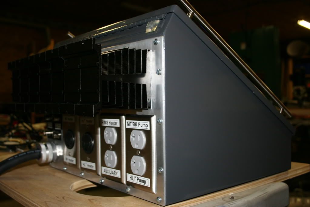
Where did you get the handles for the side of the box? Did you just some pick some industrial looking ones from a big box store? Couldn't find any on Automation direct???
Where did you get the handles for the side of the box? Did you just some pick some industrial looking ones from a big box store? Couldn't find any on Automation direct???
OP
OP
- Joined
- Nov 18, 2008
- Messages
- 2,058
- Reaction score
- 25
Hey Ed-
Where did you get the handles for the side of the box? Did you just some pick some industrial looking ones from a big box store? Couldn't find any on Automation direct???
They are brushed stainless.
I got them at Home Depot or Lowes, I don't remember which. I do remember one (not the one I got them from) was about 4 times the price. I only paid like $7 each I think.
Ed
OP
OP
- Joined
- Nov 18, 2008
- Messages
- 2,058
- Reaction score
- 25
I had assumed they were part of the box. Great addition.
That box rocks!
Thanks for the props.
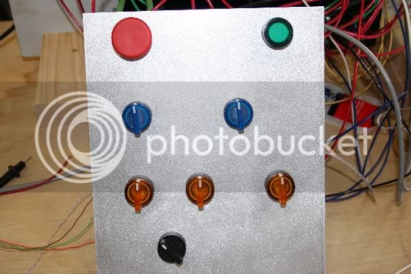
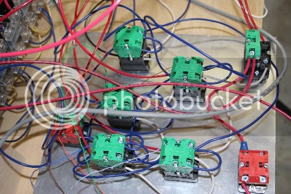
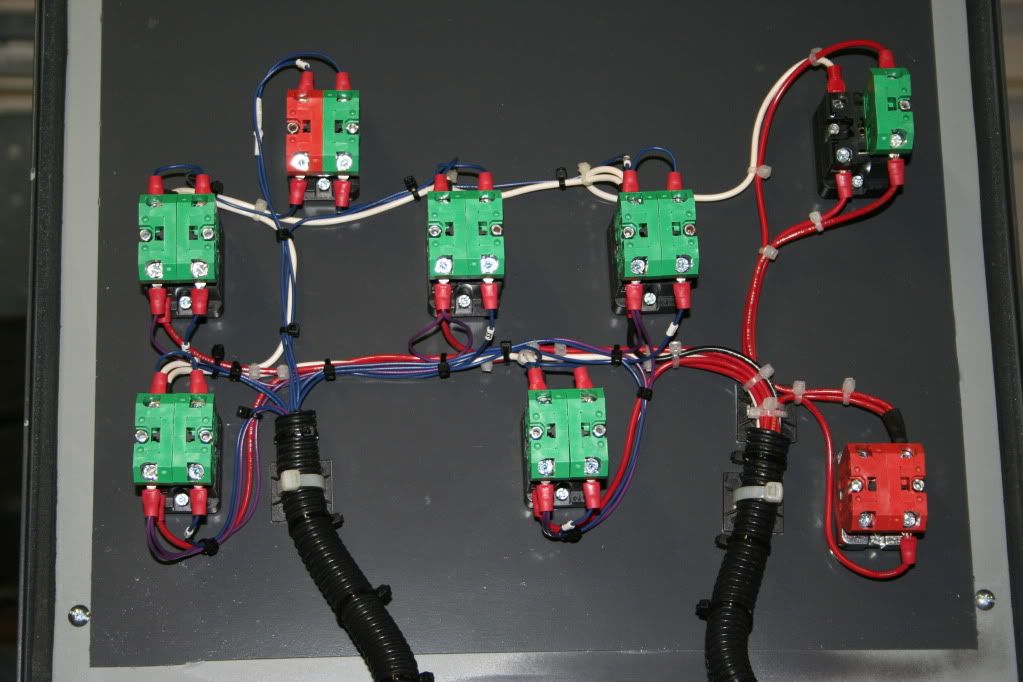
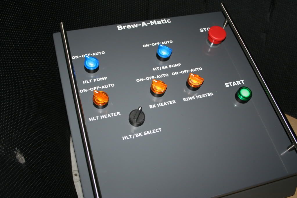
It dawned on me that I don't think I posted pics of the finished panel in this thread. I know how much we all like to see pictures so here are a few (sorry, some may have been posted in other threads):
First a couple of the prototype:
OP
OP
- Joined
- Nov 18, 2008
- Messages
- 2,058
- Reaction score
- 25
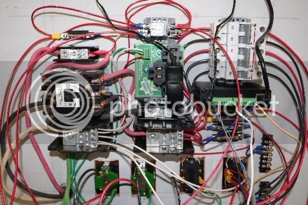
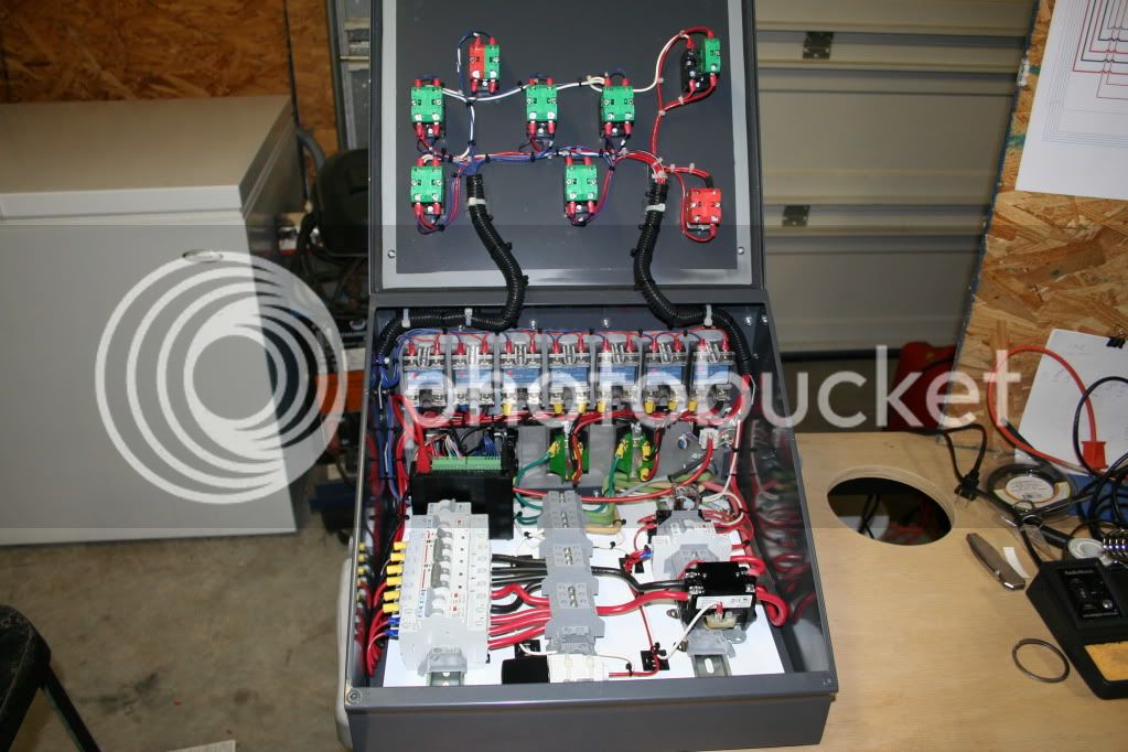
And the finished box:
OP
OP
- Joined
- Nov 18, 2008
- Messages
- 2,058
- Reaction score
- 25
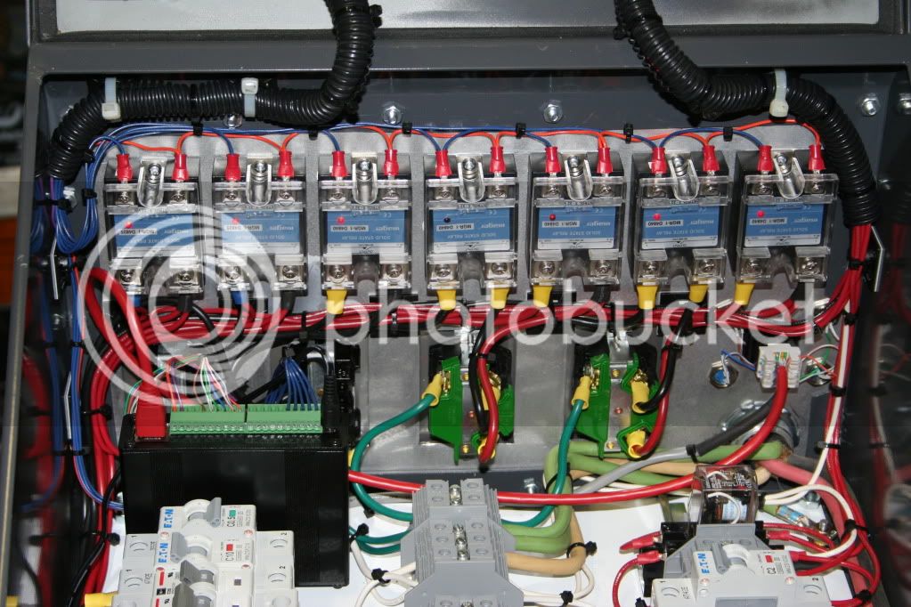
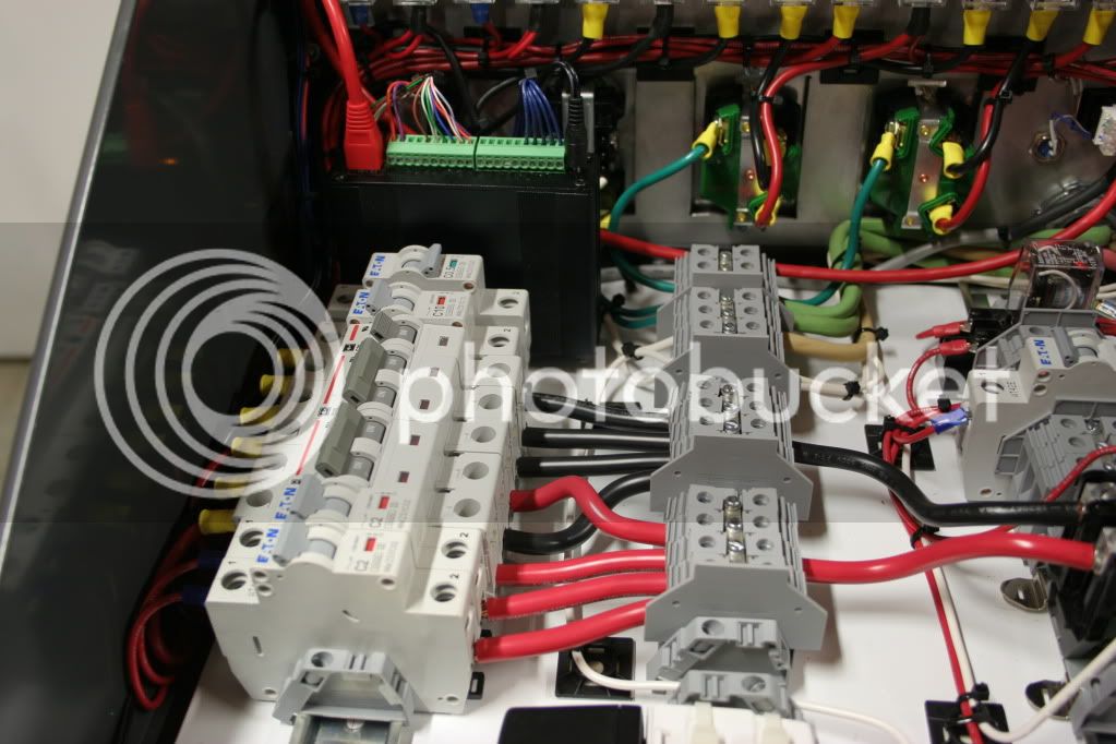
Very, very nice. Very clean. I don't think I've seen that many SSR's before. What do you do on brewday, hit the switch, set mash temperature, and walk away? Does it do hop additions?
Thanks...
2 SSR's for 5500 watt element in the HLT
2 SSR's for 5500 watt element in the BK
1 SSR for the 1500 watt RIMs Heater
1 SSR for the HLT Pump
1 SSR for the MT/BK Pump
It's BCS controlled so on brew day I don't push buttons, I click a mouse (just kidding).
I'm still working out the details of the BCS processes, so at this point, there is quite a bit of interaction.
Hop additions? Ah crap, now look what you've done... oh well, back to the drawing board.
OP
OP
- Joined
- Nov 18, 2008
- Messages
- 2,058
- Reaction score
- 25
Clean, crisp, beautifull. You should really be proud.
Thanks Layne.
To be honest, what I'm really proud of is HBT.
I ferreted out ideas from various threads and then several members contributed advice, wisdom, and wise cracks. I really do feel like it was a group effort.
Ed
I like the bumpons to keep the lid from clunking when opened. Now that is getting down to the nitty gritty!
OP
OP
- Joined
- Nov 18, 2008
- Messages
- 2,058
- Reaction score
- 25
I like the bumpons to keep the lid from clunking when opened. Now that is getting down to the nitty gritty!
That may look like attention to detail... In fact, those were installed when I realized the top hit the heat sinks :cross:
I meant to do that
caskconditioned
Well-Known Member
Wow! Incredible. Will you build me one please I'm planning on doing a very similar build (BCS, etc) so finding your thread is a huge score for me.
Electrical newbie question: Why 2 SSRs for one 5500W element?
I'm planning on doing a very similar build (BCS, etc) so finding your thread is a huge score for me.Electrical newbie question: Why 2 SSRs for one 5500W element?
Wow! Incredible. Will you build me one please
Electrical newbie question: Why 2 SSRs for one 5500W element?
In my setup I use two SSR for safety. 1 is wired to a switch on my control panel so I can turn off power to element. The other is wired to my PWM to control the element.
SO, 1 ssr for each leg. It has come in handy. I have already had a bad SSR. The one attached to the PWM failed in the ON position while I was brewing. I was able to control the element with the switch manually. It was a PITA but it saved my brewday. In an emergency too, it allows you to shut down the element.
caskconditioned
Well-Known Member
In my setup I use two SSR for safety. 1 is wired to a switch on my control panel so I can turn off power to element. The other is wired to my PWM to control the element.
SO, 1 ssr for each leg. It has come in handy. I have already had a bad SSR. The one attached to the PWM failed in the ON position while I was brewing. I was able to control the element with the switch manually. It was a PITA but it saved my brewday. In an emergency too, it allows you to shut down the element.
Thanks, that makes sense. So looking at Ed's control panel, the On | Auto | Off switch is using one SSR for the ON, one SSR for the Auto (BCS), and then the Off kills power to both. Is that correct?
Boerderij_Kabouter
Well-Known Member
No. The two SSRs are used to individually control the two out-of-phase 120VAC lines going to the element. If you only switch one leg, the other leg would still be hot. As long as nothing bad happens it would work fine, but if any weird grounding or corrosion (etc) occurs, it is possible to direct 120VAC through the element and into the system unintentionally.
It is a safety measure, but one that should absolutely be taken IMO.
The two SSRs are logically parallel, so if one switches the other does as well. They are controlled by the same source.
It is a safety measure, but one that should absolutely be taken IMO.
The two SSRs are logically parallel, so if one switches the other does as well. They are controlled by the same source.
OP
OP
- Joined
- Nov 18, 2008
- Messages
- 2,058
- Reaction score
- 25
No. The two SSRs are used to individually control the two out-of-phase 120VAC lines going to the element. If you only switch one leg, the other leg would still be hot. As long as nothing bad happens it would work fine, but if any weird grounding or corrosion (etc) occurs, it is possible to direct 120VAC through the element and into the system unintentionally.
It is a safety measure, but one that should absolutely be taken IMO.
The two SSRs are logically parallel, so if one switches the other does as well. They are controlled by the same source.
Right on the money, BK.
Also, my switches are in the low voltage "Control" lines of the SSR's.
The BCS has a terminal that provides constant +5vdc and each BCS Output has a +5vdc terminal. So my switches determine which (or none) of the BCS terminals drive the SSR's contol voltage.
Hope that makes sence.
Ed
OP
OP
- Joined
- Nov 18, 2008
- Messages
- 2,058
- Reaction score
- 25
Wow! Incredible. Will you build me one please
Electrical newbie question: Why 2 SSRs for one 5500W element?
For the right money I could probably hook you up with my prototype.

.
.
.
Just kidding... it no longer exists.
But there are a lot of parts that I will eventually put in the classified section when I get time.
Ed
caskconditioned
Well-Known Member
I clearly have a lot to learn :cross: I'm going to spend some time re-reading this entire thread. Electricity scares the hell out of me so I'm not going to do anything w/o a licensed electrician. I may have to bribe some of you experts a little later on for some assistance though. Cheers!
caskconditioned
Well-Known Member
Feel free to PM me when you are ready and I can save you the effort of listing themBut there are a lot of parts that I will eventually put in the classified section when I get time.Ed
On page 8 of this thread (re-read), so have a ways to go before hitting you up with a million questions (kidding).
OP
OP
- Joined
- Nov 18, 2008
- Messages
- 2,058
- Reaction score
- 25
Feel free to PM me when you are ready and I can save you the effort of listing them
I'm fairly mechanically inclined and have a basic knowledge of electricity.
If you are in the same boat, my suggestion is this: Do the design yourself. Don't copy mine or anyone else's. Not that I mind you using it (your are welcome to it), but rather so you understand it 100%. I was forced to learn a lot of stuff and it took many iterations (as you can see by reading this thread), but it's a good feeling to know it's mine. If it breaks, or mis-behaves, I know how to troubleshoot it and fix it. I give CodeRage huge accolades for the time he spent... I'm sure he could have just drew it up and handed it over in one tenth the time he spent. Instead, he "forced" me to "learn to fish". If this is the direction you're heading, you need to learn to communicate with the right people in their language. Find a drawing tool (I used MS Viso) and learn the electrical symbols for the devices you need. It can be a bit frustrating... the response to many questions, is more questions. In my case, I realized that just means my design/options were not as black and white as I thought, so back to the books(web).
I'm happy to help as far as my experience and knowledge goes.
caskconditioned
Well-Known Member
Thank you Ed. I agree, I need to learn all this vs. having someone just tell me what to do. Having your build as a starting point will definitely help me learn all this faster. I also have some slightly different requirements so knowing how it all works will help me make the necessary changes.
Just stumbled across this thread and all I can say is WOW! This is exactly the type of info I was looking for.
Great job Ed and thanks for sharing your project.
And also a thanks to CodeRage for all the tech support.
Great job Ed and thanks for sharing your project.
And also a thanks to CodeRage for all the tech support.
EuBrew
Well-Known Member
Awesome work Ed!
I'm getting ready to build a Brewtroller rig myself so I've been trolling as much as I can to learn from the masters
I've looked at your diagram and your panel and I'm having a hard time figuring out where all the breakers go. Here's what I think I see
30A DP breaker = 5500 watt element 1
30A DP breaker = 5500 watt element 2
20A SP breaker = 1500 watt RIMS element
2A breaker =pump 1
2A breaker =pump 2
2A breaker =BCS power supply??
5A breaker =EMPTY???
10A breaker =????? something connected
I'm missing something here, can you help out the moron (me) here?
OP
OP
- Joined
- Nov 18, 2008
- Messages
- 2,058
- Reaction score
- 25
Awesome work Ed!
I'm getting ready to build a Brewtroller rig myself so I've been trolling as much as I can to learn from the masters
I've looked at your diagram and your panel and I'm having a hard time figuring out where all the breakers go. Here's what I think I see
30A DP breaker = 5500 watt element 1
30A DP breaker = 5500 watt element 2
20A SP breaker = 1500 watt RIMS element
2A breaker =pump 1
2A breaker =pump 2
2A breaker =BCS power supply??
5A breaker =EMPTY???
10A breaker =????? something connected
I'm missing something here, can you help out the moron (me) here?
Thanks.
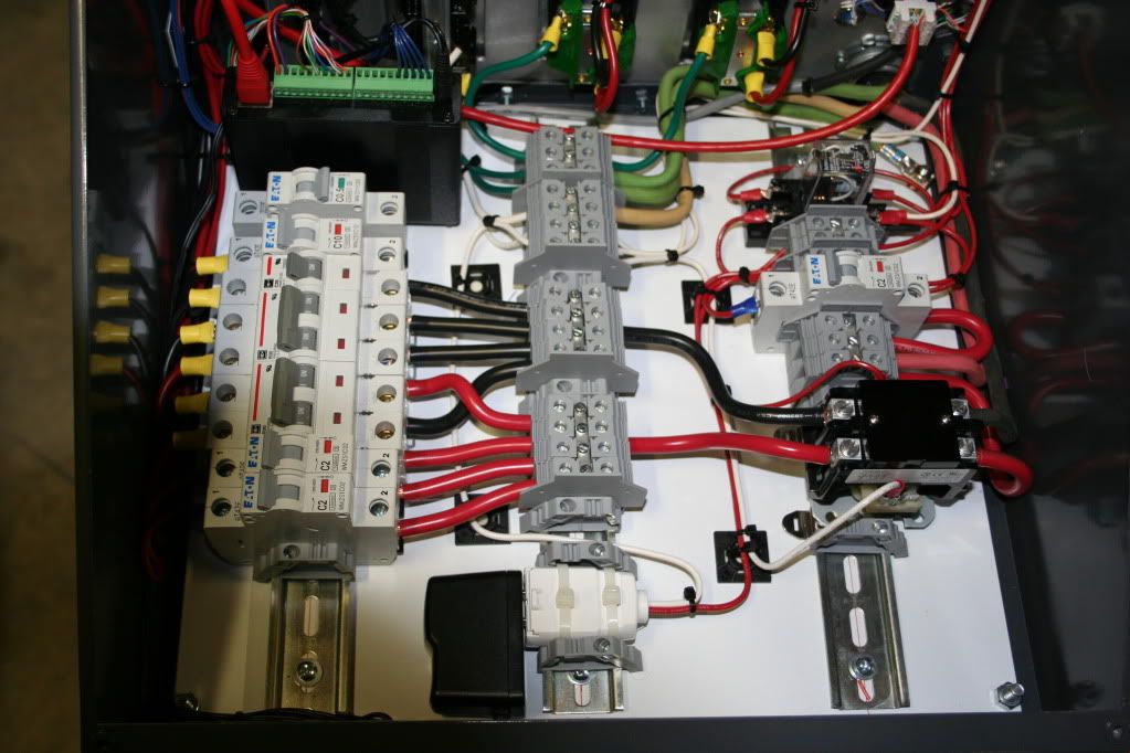
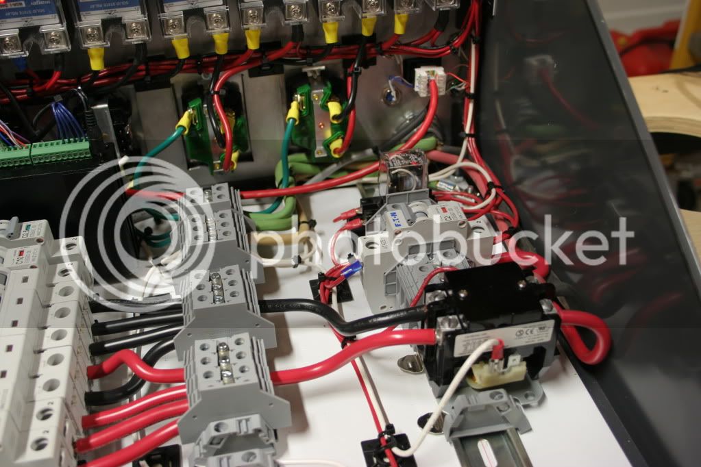
Here is where the breakers go and their relationship to the drawings:
30A DP breaker = 5500 watt element 1 (f2 & f3)
30A DP breaker = 5500 watt element 2 (f4 & f5)
20A SP breaker = 1500 watt RIMS element (f6)
2A breaker =pump 1 (f7)
2A breaker =pump 2 (f8)
You were correct on the above, here is the rest:
2A breaker =BCS power supply and E-Stop Circuit (I combined f1 & f10 in front of the contactor)
0.5A (not 5a) breaker = BCS +5vdc output (f9 - not wired in the photo)
10A breaker = Auxiliary Receptacle (I have a Wireless bridge plugged in) This breaker is not in the drawing.
Hope that helps.
Ed
EuBrew
Well-Known Member
Yep, now I just need to figure out what breaker sizes I need for the brewtroller 12V 3A power supply (guessing 5A) and if the 16 output relay board for my valves needs a breaker as well. I wish this was as easy for me as wiring my house was, passed inspection first time without near the reading I've done on this already!!
OP
OP
- Joined
- Nov 18, 2008
- Messages
- 2,058
- Reaction score
- 25
Yep, now I just need to figure out what breaker sizes I need for the brewtroller 12V 3A power supply (guessing 5A) and if the 16 output relay board for my valves needs a breaker as well. I wish this was as easy for me as wiring my house was, passed inspection first time without near the reading I've done on this already!!
I did not fuse each output of the BCS.
The BCS has a +5vdc output that is constant and not "controlled" by the BCS. I used it to feed power to all the SSR's when switched to the manual mode. This is the only output of the BCS I fused.
Good luck,
Ed
Eubrew - 5A is fine for the power supply and it should be placed on the power supply's 120V supply. You should use an appropriately sized fuse protect any 120V (or 240v) piece of equipment your using. The fuses protect the devices from over current surges. Are your valves line voltage or low voltage? You can do as Ohio-Ed said and use one fuse to protect all of the valves from a spike over their rated max amp.
EuBrew
Well-Known Member
Thanks fellas! I really should start my own thread here (sorry to hijack Ed). I will start one here in a bit once all my stuff gets here and I start building.
I'll be using the following
30A DP breakers for my 2 (one each) 5500 watt elements
20A DP breaker for my 3500 watt element
2A SP breakers for my pumps
5A SP breaker for brewtroller power supply
not sure about the 16 output relay board yet for protecting valves etc.
Valves will be the ones in the BT store unless it takes me long enough to get to building that jcdillin has gotten the 3 way valves sourced, then it's up in the air. I'm guessing they will be 12V DC like the valves in the store.
Also up in the air are my stir motors for the HEX and the HLT.
still have some research to do.
Thanks again for the input!
ClaudiusB
Well-Known Member
And the finished box:
What a very well executed project

Cheers,
ClaudiusB
sco999
Well-Known Member
OhioEd,
Thanks for this amazing thread!! Thanks to all who have contributed.
I am in the process of purchasing components for my E-Brewery. I am using 5500 watts in the BK, 5500 watts in the HLT, and 1500 watts in the RIMS all elements are 240vac to keep me on a 40 amp circuit. I have a few questions.
1) Will a 3 pole 10amp 120vac Ice cube relay work instead of the 2 Pole for the E-stop?
2) What contactors does the 2 position selector switch need? 1NO & 1NC?
3) What curve breakers are you using? B for the elements and D for the rest?
4) Would a 1 amp breaker work for F9?
5) Do you have a link for your terminal blocks? Do they require jumpers, or do they direct contact each other and need to be terminated with end plates?
6) What size enclosure should I look for? 12"x12"x6" or 16"x12"x6"? I will be utilizing din rails, but I will have 8 ssr's due to my Rims Element being 240vac.
Thanks,
OP
OP
- Joined
- Nov 18, 2008
- Messages
- 2,058
- Reaction score
- 25
OhioEd,
Thanks for this amazing thread!! Thanks to all who have contributed.
I am in the process of purchasing components for my E-Brewery. I am using 5500 watts in the BK, 5500 watts in the HLT, and 1500 watts in the RIMS all elements are 240vac to keep me on a 40 amp circuit. I have a few questions.
1) Will a 3 pole 10amp 120vac Ice cube relay work instead of the 2 Pole for the E-stop?
Sure, just leave the 3rd pole empty. Here is the Relay and Socket I used:
http://www.automationdirect.com/adc.../5A_Electro-Mechanical_Cube_Relays/QM2N1-A120
http://www.automationdirect.com/adc...-_Timers/Relay_Sockets_-a-_Accessories/SQM08D
2) What contactors does the 2 position selector switch need? 1NO & 1NC?
Yes, 1 NO and 1 NC
3) What curve breakers are you using? B for the elements and D for the rest?
Actually, I bought based on what was on-hand at the time I ordered which was are all C Curve except the 30amp double poles which are B Curve. They all came from AutomationDirect.
4) Would a 1 amp breaker work for F9?
F9 is intended to protect the BCS. The max current on the +5vdc is 300mA, so really the fuse should be less than 300mA. I ended up with a .5a breaker, because it was what I could find...not 100% sure it would really save the BCS.
5) Do you have a link for your terminal blocks? Do they require jumpers, or do they direct contact each other and need to be terminated with end plates?
The terminal blocks came from Mouser.com. I used a variety of sizes. They do require a jumper bar if you need to connect them. The jumpers come in various sizes, you "can" buy longer ones and cut them down as needed if you don't know exactly what you need.
I downloaded a PDF of the Manufacturers Terminal blocks & accessories and hunted down the sizes and pieces I needed.
Here is a link to one of the terminal blocks...
http://www.mouser.com/Search/ProductDetail.aspx?R=CTS10Uvirtualkey56110000virtualkey845-CTS10U
6) What size enclosure should I look for? 12"x12"x6" or 16"x12"x6"? I will be utilizing din rails, but I will have 8 ssr's due to my Rims Element being 240vac.
I think you could accommodate what I have in a 16"x12"x6" square box but size will depend on what devices you need to mount... There are no Timers, displays, or PID's on my panel so I actually had plenty of real estate on the front panel. The back with all the SSR's and connectors was quite tight. Also, the slant top on my box made mounting components close to the front challenging.
Thanks,
I hope that helps...
Ed
Similar threads
- Replies
- 20
- Views
- 809
