Homebrew Talk - Beer, Wine, Mead, & Cider Brewing Discussion Forum

Help Support Homebrew Talk - Beer, Wine, Mead, & Cider Brewing Discussion Forum:

This site may earn a commission from merchant affiliate links, including eBay, Amazon, and others.

EthanWalker

Member
Joined
Mar 17, 2015
Messages
15
Reaction score
1
Location
Altoona
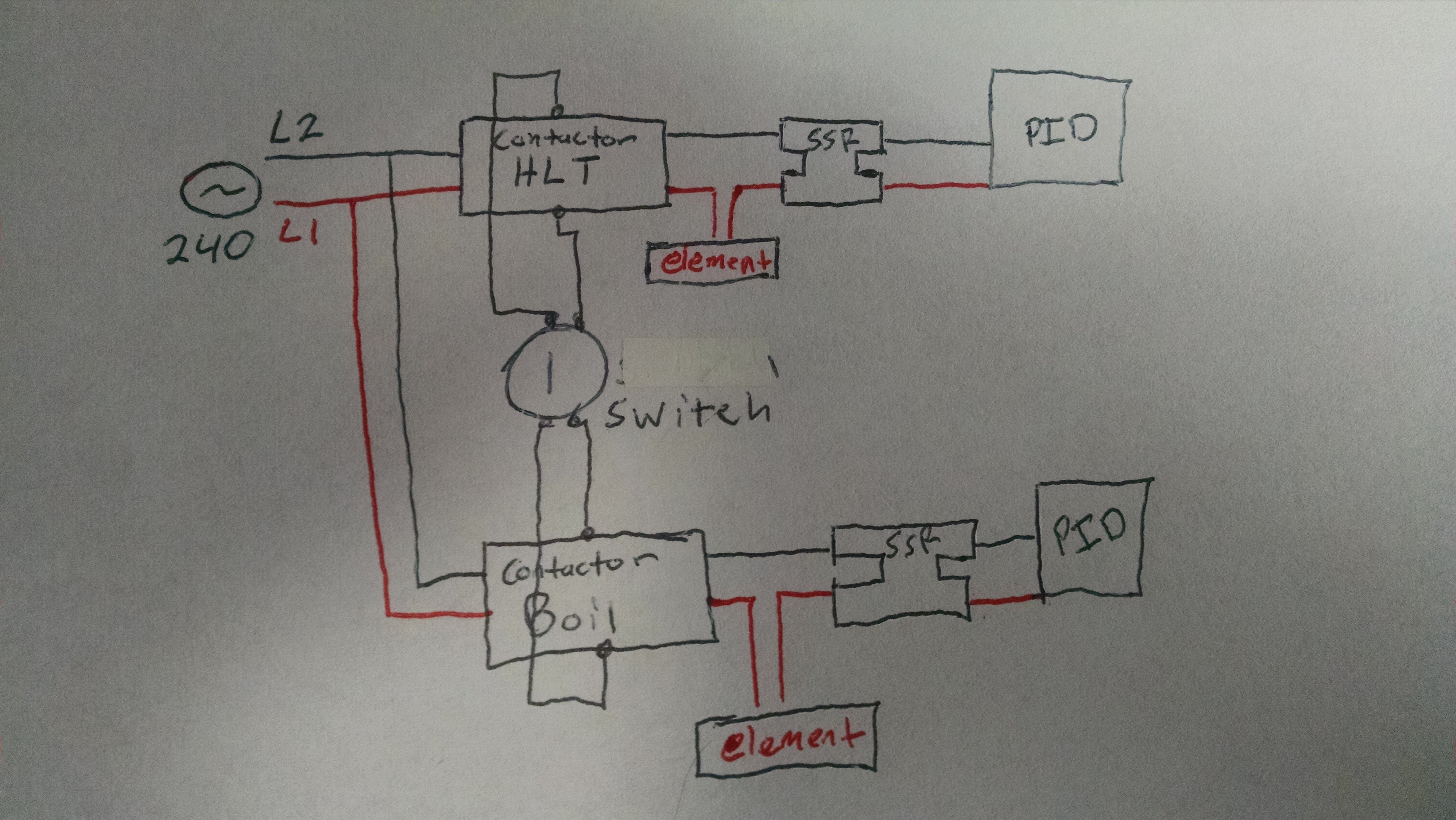
I currently have a control panel wired for 1 HLT heating element. It is wired into 1 SSR and the PID. I am wanting to add another heating element for the boil kettle. After looking at some diagrams they have contactors added with a switch with the SSR still wired to the heating element :
upload_2019-3-10_11-4-25.png

Below is another diagram, but the SSR is NOT wired into the element. I am wanting to add a switch so I can power the HLT or the BK. My question is how do you wire the contactor and SSR? Does the SSR wire into the Contactor then into the element OR does the contactor and SSR wire into the element like the diagram above? If I go off the above diagram would I duplicate the same for each element with SW1 controlling which element gets turned on?
upload_2019-3-10_11-6-2.png

My understanding is contractors aren't as fast/precise as SSR at controlling a heating element so why would you wire the contactor directly into the heating element? Wouldn't it be better to have the SSR wired into the element?

Thank you for any advice or suggestions.
 
I believe SSR's fail in the closed position, so the contactors are a safeguard against that. You turn the contactors on and then switch the SSR's on/off to control the element. The contactors give you the ability to cut the power to the element if the SSR's have failed.
 
I do not see the control wiring for the contactor in the second diagram, but the contactor is most likely not actively switched to control(regulate power) to the element.
 
Both solutions will work just as fine. I suppose that in both cases the role of the contactors is to be able to manually override the PID controller but only by turning the load off manually. If the SSR is in the open position switching the contactor in the closed position will not manually turn on the load.
 
I don't think it's going to matter much either way. In both cases, the contactor is going to break the circuit. Realize that both the SSR and contactor have to be on in order for the element to have power. The contactor is there as a full shut-off, you will turn it on or off manually with your switch. When it is on, the SSR will modulate the power that goes to the element.

The comment about contactors not being as fast/precise is in the context of PID control. A SSR is best controlled by a PID, a contactor is best controlled by a switch.
 
I believe SSR's fail in the closed position, so the contactors are a safeguard against that. You turn the contactors on and then switch the SSR's on/off to control the element. The contactors give you the ability to cut the power to the element if the SSR's have failed.
So in my mind you would have the SSR wired to the heating element not the contactor like in the second image.
 
So in my mind you would have the SSR wired to the heating element not the contactor like in the second image.
The SSR is most likely wired to the heating element through the contactor in that diagram. Further to the left, I would imagine the red wires are connecting to a heating element.
 
I put my contactor on the input to my control panel. In case something goes bad inside the box the kill switch limits live line voltage to just a few connections. I have switches on the SSR outputs to the elements for individual control.
 
I'm going to have to find someone. This is over my head.
That question wasn't meant to discourage you from building the panel, but you are talking about designing a high voltage panel that you will be using to control elements immersed in water. It's best that you understand what you're doing AND have someone who knows what they're doing check your work. You can get a lot of help here on HBT and there's lots of resources online (including that ebrewsupply link that @Gravitysucks posted) but if you're not fully confident in what you're doing, some in-person help might be best.
 
A contactor is an inline switch that you, as the operator, purposefully open or close to make sure the element is OFF when you need it off. It usually kills both L1 and L2 on the supply for extra safety. In the case of element selector switches, when you use a 3 way switch with center off, it both kills the power to the elements and selects which one can be turned on depending on which position you select and then what contactor is enabled.

The SSR is also a switch but it's driven on/off by the temp controller and usually only a single leg of the 240 runs through it.

There are a few ways to approach this. The contactors can go first, then to to the SSR, then to the elements. This method requires two SSRs and they are technically both trying to fire whenever the controllers want them to. It's just that one of them won't be getting any voltage due to the upstream contactor.

An alternative is to use a single SSR upstream and then split to two contactors downstream right before the element outputs. This gives you two options. First, if you only want boil control in the boil kettle with no temperature resolution or control, you can use a single PID/EZboil (along with the single SSR) and the selector switch is just deciding which element is live. The PID would get a probe from the HLT.
The second thing you can do is continue to use two controllers but in that case the selector switch would also need switch blocks to select which PID's control circuit is getting to the SSR. This at least lets you still have a realtime temp reading on both vessels and you'll still have temp control options in the boil kettle (kettle souring and such).

Reducing down to one SSR is not that big of a cost savings by itself but it also let's you use a smaller heat sink.
 
That question wasn't meant to discourage you from building the panel, but you are talking about designing a high voltage panel that you will be using to control elements immersed in water. It's best that you understand what you're doing AND have someone who knows what they're doing check your work. You can get a lot of help here on HBT and there's lots of resources online (including that ebrewsupply link that @Gravitysucks posted) but if you're not fully confident in what you're doing, some in-person help might be best.
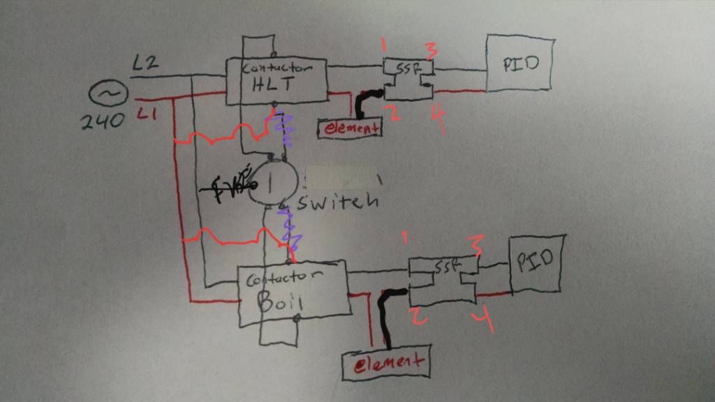
So was I close with my drawing? I just copied exactly how Auber wired the contactor (First diagram). I just added a switch for a second contactor. I'm assuming I messed up with the switch. I know a local electrician and when I have a good diagram I was going to run it by him and have him double check all my work once installed.
And my original question did get answered; it doesn't really matter which one is first as long as they (contactor & SSR) are wired in a series. Thank you!
I guess now I need to figure out how to actually put it all together.
 
A contactor is an inline switch that you, as the operator, purposefully open or close to make sure the element is OFF when you need it off. It usually kills both L1 and L2 on the supply for extra safety. In the case of element selector switches, when you use a 3 way switch with center off, it both kills the power to the elements and selects which one can be turned on depending on which position you select and then what contactor is enabled.

The SSR is also a switch but it's driven on/off by the temp controller and usually only a single leg of the 240 runs through it.
Also, an SSR is not an "ideal" switch as it does not completely cut off current, or remove voltage from the load. They basically switch between a low value resistance and a high value resistance. You can get a shock at the load terminals even when the SSR is off. A mechanical switch in contrast does completely cut off current and removes voltage from the downstream side. The switch from very low resistance to (essentially) infinite resistance.

There are a few ways to approach this. The contactors can go first, then to to the SSR, then to the elements. This method requires two SSRs and they are technically both trying to fire whenever the controllers want them to. It's just that one of them won't be getting any voltage due to the upstream contactor.
This is incorrect, you never need two SSR's. Current always flows thru a loop, and you can interrupt the current by breaking the loop anywhere. You need two pole contactors (in a 240V system) in order to remove downstream voltage, since both legs carry voltage potential (and can also drive current, if there is a closed loop.) P-J used to design with the contactor downstream of the SSR. I design with the contactor upstream of the SSR. Both work the same in practice. I like the contactor upstream, as it de-energizes more of the circuitry when the contactors are off, and I think that is just a better design philosophy.

...

Brew on :mug:
 
So was I close with my drawing? I just copied exactly how Auber wired the contactor (First diagram). I just added a switch for a second contactor. I'm assuming I messed up with the switch. I know a local electrician and when I have a good diagram I was going to run it by him and have him double check all my work once installed.
And my original question did get answered; it doesn't really matter which one is first as long as they (contactor & SSR) are wired in a series. Thank you!
I guess now I need to figure out how to actually put it all together.
Yeah, your drawing was close. The only issue I see as that you didn't wire the contactor coils correctly. One side gets a switched hot, the other side connects to neutral (unswitched.) If you use contactors with 240V coils then you connect one side to hot1 and the other to hot2.

Here's a design I did that shows how to do what you want to do (it also has a few more features that you may or may not want.)

HERMS for Video.PNG


Brew on :mug:
 
Why not? Drawing done by unusual way but circuits are OK
So, if i interpret it one way and assume two lines are the wrong color, but wired to the element correctly, you're right. If I interpret it another way, the element is wired incorrectly and we have L1 and L2 shorted to each other when the SSR is fired by the PID. The drawing does not make clear how the element is wired, and at my first glance I followed the colors.
 
Why not? Drawing done by unusual way but circuits are OK
No power to the contactor switch looks like the biggest problem to me, the color coding choices are mostly for clarity.

If that's a 240v coil and a standard 2-NO 3-POS selector you could fix it like this, include a fuse to protect low amperage wires and components.
20190311_200618.jpeg
 
The contactor is a mechanical isolation of both L1 AND L2 from the element. The SSR is using a pulse width signal from the controller to effectively transition the element from 110V to 240V at a rate that the controller decides by switching only one leg, L1 or L2. I much prefer the SSR after the contactor because micro controllers like Arduino and RPI ride the PWM signal on a high "base" frequency because they are designed for DC servos, which essentially ignore the AC signal (40KHz) but can jump the contactor making it a spark gap.
 
The contactor is a mechanical isolation of both L1 AND L2 from the element. The SSR is using a pulse width signal from the controller to effectively transition the element from 110V to 240V at a rate that the controller decides by switching only one leg, L1 or L2. I much prefer the SSR after the contactor because micro controllers like Arduino and RPI ride the PWM signal on a high "base" frequency because they are designed for DC servos, which essentially ignore the AC signal (40KHz) but can jump the contactor making it a spark gap.

I don't believe the statement about transitioning the element voltage between 110 volts and 240 volts is accurate for the majority of electric systems.

In order to switch the element voltage between 120 and 240 volts, you would need another switch to connect one side of the element between the L2 and the neutral while keeping the other side of the element connected to L1.
For most electric systems using a controller, the typical practice is to switch the element between the full 240 VAC and 0 VAC (off).
 
Last edited:
The contactor is a mechanical isolation of both L1 AND L2 from the element. The SSR is using a pulse width signal from the controller to effectively transition the element from 110V to 240V at a rate that the controller decides by switching only one leg, L1 or L2. ...
I don't believe the statement about transitioning the element voltage between 110 volts and 240 volts is accurate for the majority of electric systems.

In order to switch the element voltage between 120 and 240 volts, you would need another switch to connect one side of the element between the L2 and the neutral while keeping the other side of the element connected to L1.
For most electric systems using a controller, the typical practice is to switch the element between the full 240 VAC and 0 VAC (off).
SSR behavior is widely misunderstood. An SSR is not a voltage switch, but rather a current modulator that doesn't eliminate current flow when off, but rather just reduces it by a few orders of magnitude. SSR's typically leak something on the order of 1mA when off, when working with line voltages.

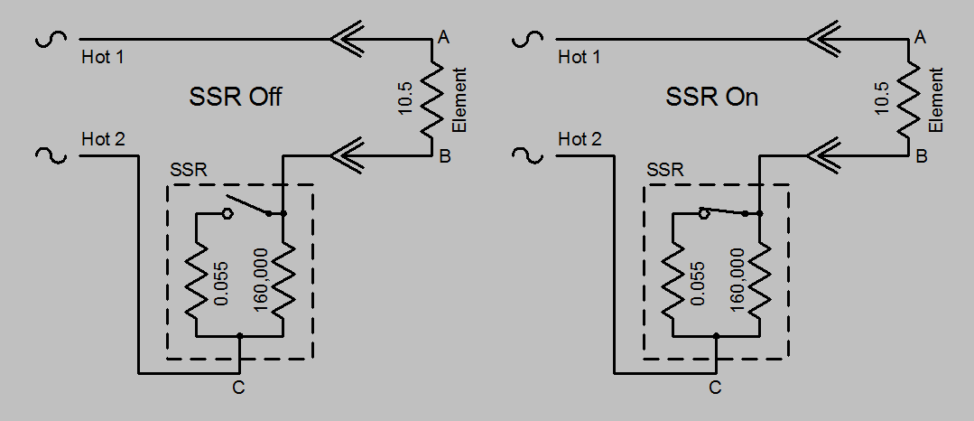
A good model for understanding SSR behavior is a pair of resistors, one a high value resistor that is always connected between the power terminals, and the other a low value resistor that is switched to be either disconnected, or connected in parallel with the high value resistor. This is shown in the schematic below:

SSR Model.PNG

To analyze this circuit we need to use Ohm's law, which can be written three different ways, depending on what value you want to calculate:
V = I * R
R = V / I
I = V / R​
And we also need the equation for power, which has some alternates if you substitute the first and third forms of Ohm's law into the basic formula:
P = I * V
P = I^2 * R
P = V^2 / R​

The value of the larger resistor in the SSR model is picked to get about 1.5 mA leakage @ 240V, so the value is:
R = V / I = 240V / 0.0015A = 160,000 ohms
The voltage drop across the SSR at operating current (22.9 A for 5500 W element) is about 1.25 V, so the value of the smaller resistor needs to be:
R = V / I = 1.25V / 22.9 A = 0.055 ohms​

A 5500W element at 240V needs to have a resistance of:
R = V^2 / P = 240V^2 / 5500W = 10.5 ohms
And finally the operating current for 5500 W @ 240 V is:
I = P / V = 5500W / 240V = 22.9 A​

The circuit is powered by Hot 1 and Hot 2 both of which are 120 V measured against ground. Since they are 180° out of phase with each other, the voltage measured between points "A" and "C" will be 240 V always (whether the element is plugged in or not, and whether the SSR is off or on.) Point "A" will always be 120 V to ground, as will point "C".

What happens to the voltage at point "B" is what gets interesting.

With the element plugged in, and the SSR off, we have a 10.5 ohm resistor in series with a 160,000 ohm resistor. The total resistance for the loop is then 160,000 + 10.5 = 160,010.5 ohms, and the current flowing is 240V / 160,010.5 = 0.0014999 A, so let's just call it 0.0015 A (1.5 mA - the extra 10.5 ohms of the element has almost no effect on the current flow.) The voltage difference between points "A" and "B" (i.e. voltage on the element) is:
V = I * R = 0.0015A * 10.9 ohms = 0.016 V​
So, the voltage at point "A" to ground will be 120 V, and point "B" to ground will be 120 - 0.016 = 119.984, and the power on the "off" element will be 0.0015^2 * 10.5 = 0.0000236 W. Thus the SSR is very effective at removing power from the element, but does not remove voltage from the element. The voltage difference between points "B" and "C" will be 120V + 119.984V = 239.984 V. The power being dissipated by the "off" SSR will be 0.0015^2 * 160,000 = 0.36 W.

With the element plugged in, and the SSR on, the two resisters in the SSR are in parallel, and the formula for the combined resistance from "B" to "C" is:
R[total] = R[1] * R[2] / (R[1] + R[2]) = 0.055 * 160,000 / (0.055 + 160,000) = 0.0549998 ohms
(let's call it 0.055 ohms - here the large resistance in parallel with the small resistance has essentially zero effect.)​
So, now we have a 10.5 ohm resistor in series with a 0.055 ohm resistor, for an effective resistance of 10.555 ohms. The current will then be 240V / 10.555 = 22.74 A. The voltage across the element (point "A" to "B") will be 22.74A * 10.5 ohms = 238.75 V. Voltage from "B" to "C" will then be 240V - 238.75V = 1.25 V, and "B" to ground will be 118.75 V. The power to the element will be 238.75V * 22.74A = 5429 W, and the power dissipated in the SSR will be 1.25V * 22.74A = 28 W (which is why they need heat sinks.)

With the element unplugged, and the SSR on or off, there will be 0 current flowing from "A" to "C" (and likewise 0 from "A" to "B" and "B" to "C".) With 0 current, there is 0 voltage drop, so "A" to "B" and "A" to "C" will measure 240 V, and "B" to "C" will measure 0 V. "A", "B", and "C" will all measure 120V to ground.

Brew on :mug:
 
Great explanation of the theory behind these devices. All of which can make it confusing to attempt to troubleshoot SSR circuit problems with the load disconnected.

The SSR needs a load like the element, or a substitute, connected to it to draw some current through the internal resistance of the SSR. Only then will you get a useful voltmeter reading to show if the unit is switching properly
 
Last edited:
Great explanation of the theory behind these devices. All of which can make it confusing to attempt to troubleshoot SSR circuit problems with the load disconnected.

The SSR needs a load like the element, or a substitute, connected to it to draw some current through the internal resistance of the SSR. Only then will you get a useful voltmeter reading to show if the unit is switching properly
Correct. Also, if you have an LED indicator wired in parallel with the element (which you should) it can light up (dimly) constantly when the element is not connected.

Brew on :mug:
 
Back
Top