There should be a ground screw on the 3032 switch. If not, you can attach the ground to the metal frame of the switch. This can be done by adding a nut to one of the switch mounting screws.
Brew on
Brew on


Black, white and bare would be hot, hot, ground. A neutral wire needs to be insulated to meet code, since a neutral is intended to be a current carrying conductor in normal operation, but a ground conductor should carry current only in a fault situation. You can use a neutral as ground in a 240V system, as long as you don't have any 120V requirements, in which case you need a neutral and a ground.It's coming along nicely, I've got the box all buttoned up and I'm convinced that it'll be just fine! I even made a cool mount for my raspberry pi to keep it upright inside the box. Time will tell if it gets too hot in there with the SSR and heatsink, if it does I'll just move the heat sink outside the box.
For what I think is going to be my final question, the wires in the wall are black, white and bare (connected to a 30 amp double pole breaker in the main panel). I plan on wiring these to a dryer outlet with three prongs, adding a dryer cord to the spa panel and then wiring the control panel directly to the spa panel. The directions for the dryer cord outlet say that it should have a red wire a black wire and a white wire. Is there any concern attaching it with my method?
As always you guys are unbelievable for taking the time to answer questions and bring me from zero knowledge to at least something!

That's great news and in line with what I was thinking. There isn't any 120 in the control box.Black, white and bare would be hot, hot, ground. A neutral wire needs to be insulated to meet code, since a neutral is intended to be a current carrying conductor in normal operation, but a ground conductor should carry current only in a fault situation. You can use a neutral as ground in a 240V system, as long as you don't have any 120V requirements, in which case you need a neutral and a ground.
As long as you meet the no 120V requirement, you can use a three wire dryer plug. Color matching the hots is irrelevant, but the green and bare need to be paired.
Brew on
Wire as shown in the attachment to this post. You might find some of the post following that post informative.That's great news and in line with what I was thinking. There isn't any 120 in the control box.
My trouble is figuring out how to wire the spa panel to the 3 wire and still have GFCI protection. Searching HBT and the web just leads to a "yes,no maybe so" confusion?


In a different thread when I asked a similar question for the heat element - a user named "itsnotrequired" posted this:That's great news and in line with what I was thinking. There isn't any 120 in the control box.
My trouble is figuring out how to wire the spa panel to the 3 wire and still have GFCI protection. Searching HBT and the web just leads to a "yes,no maybe so" confusion?
Yes the whole idea is that it trips fast enough to save your life when any current leaks.Sounds good - I like the idea of testing it with a resistor.
It looks like it should trip if I connect a 47KΩ between the ground screw and the load side of the Levitron switch in the box ?
Will turning the switch on immediately trip the GFI ?
Use a 15 K ohm, or slightly smaller resistor.Sounds good - I like the idea of testing it with a resistor.
It looks like it should trip if I connect a 47KΩ between the ground screw and the load side of the Levitron switch in the box ?
Will turning the switch on immediately trip the GFI ?

Good point. Since the GFCI breaker (or any breaker) isn't wired to ground, the test circuit resistor cannot be connected to ground. Thus the resistor must be connected to neutral on the source side of the current sensing coil (if connected on the load side of the coil, the test circuit won't work.)At the risk of causing confusion.......
In a different thread when I asked a similar question for the heat element - a user named "itsnotrequired" posted this:
many gfci breakers need that neutral connection for the test button to function properly. the gfci will still function properly without the neutral, it is just the test button won't work. the problem is when there is NOT a neutral coming into the spa panel and folks start jumpering neutral to ground...
And this confirms the post that doug293cz mentions above.
So it appears that you really don't have to worry about it. Just DON'T connect your neutral and ground together in any sub-panel. The only place they can be tied are in the main panel in the house (or wherever the power from the electric company arrives).

I feel like I'm getting confused again..Good point. Since the GFCI breaker (or any breaker) isn't wired to ground, the test circuit resistor cannot be connected to ground. Thus the resistor must be connected to neutral on the source side of the current sensing coil (if connected on the load side of the coil, the test circuit won't work.)
To get the "Test" button to work in a spa panel breaker, where there is no neutral coming from the main breaker, you should connect the pigtail from the GFCI breaker to the ground bus in the spa panel. This provides a completed current path for the test current to flow when the button is pushed. Do not connect anything to the load side neutral terminal of the GFCI breaker.
Brew on
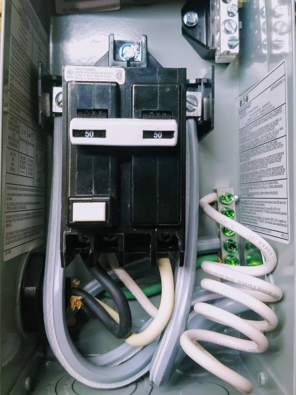
Yes. Otherwise, the "Test" button on the GFCI breaker won't work.I feel like I'm getting confused again..
Is it correct that the two hot lines (in) should connect to the obvious places in the panel, the ground should go to the ground bus and then the two hot loads should go to either side of the breakers avoiding the one with the pigtail, and the pigtail should go to the ground bar ?
Like this ?
View attachment 622472

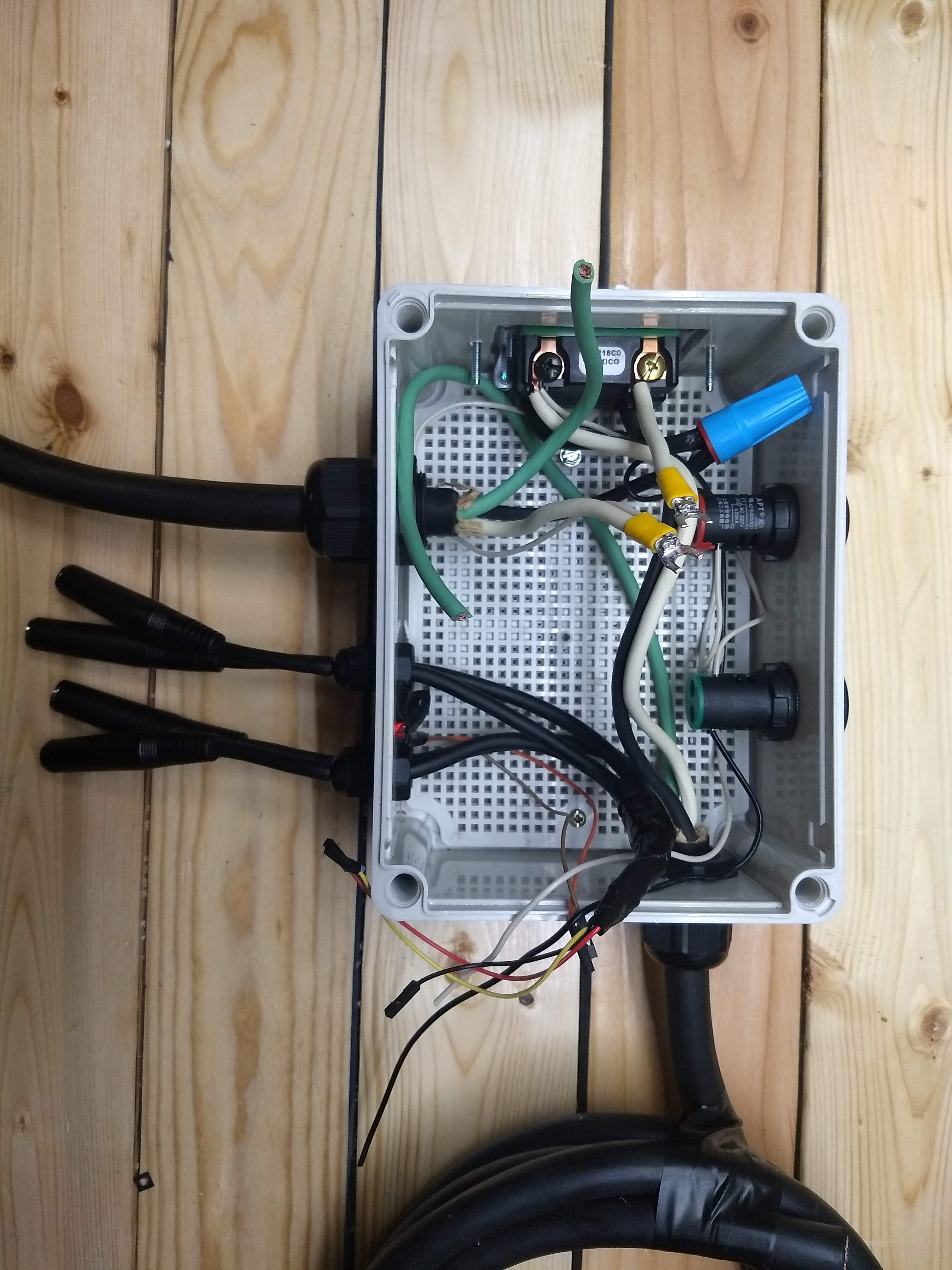
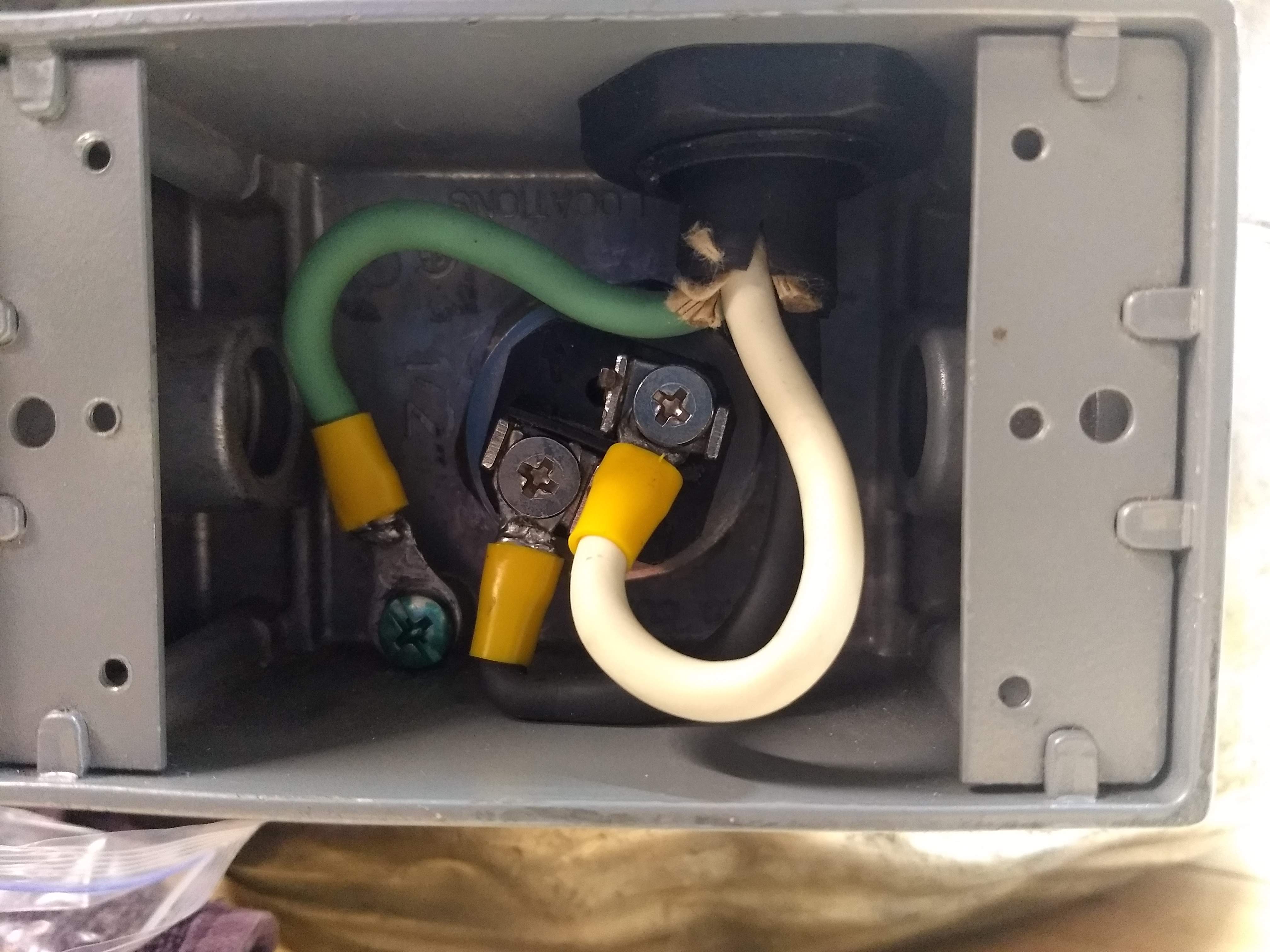
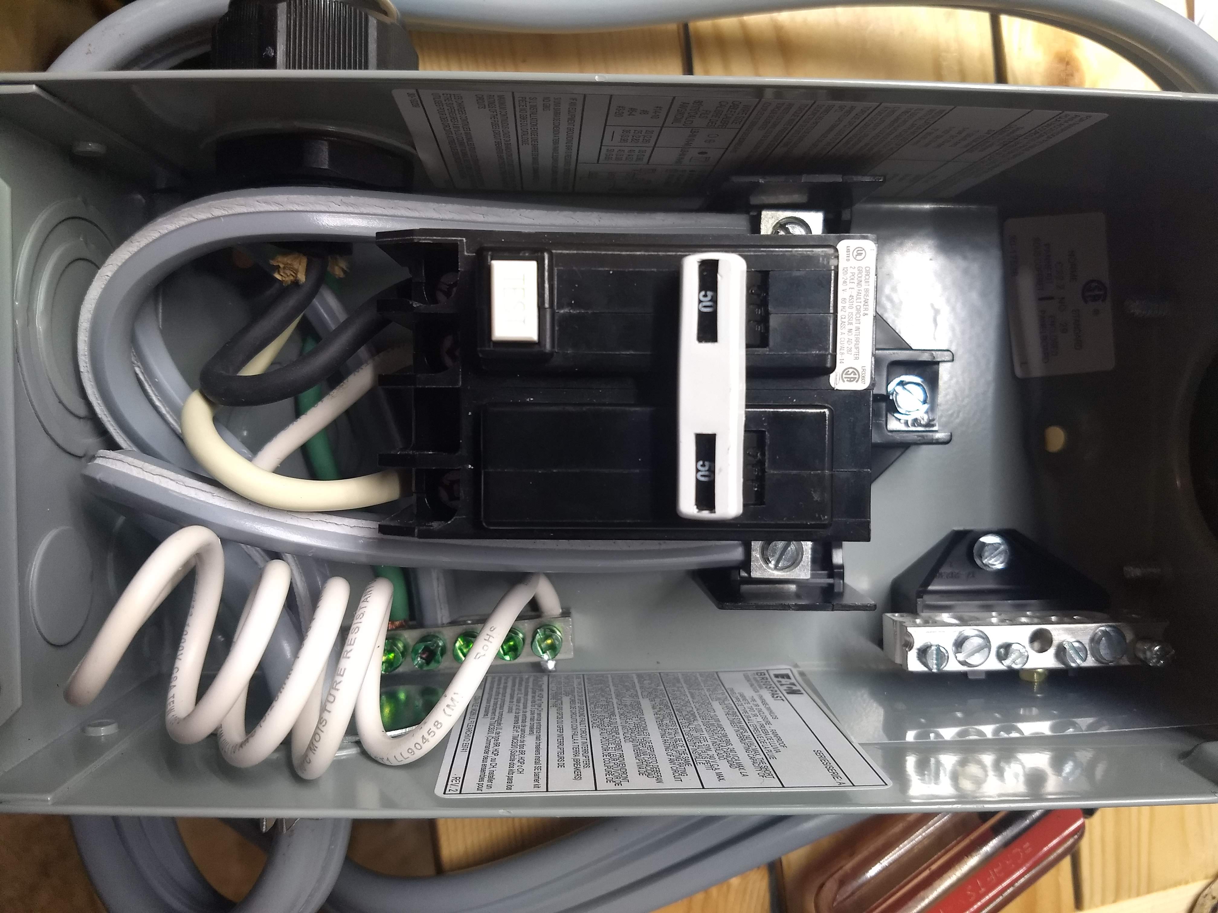

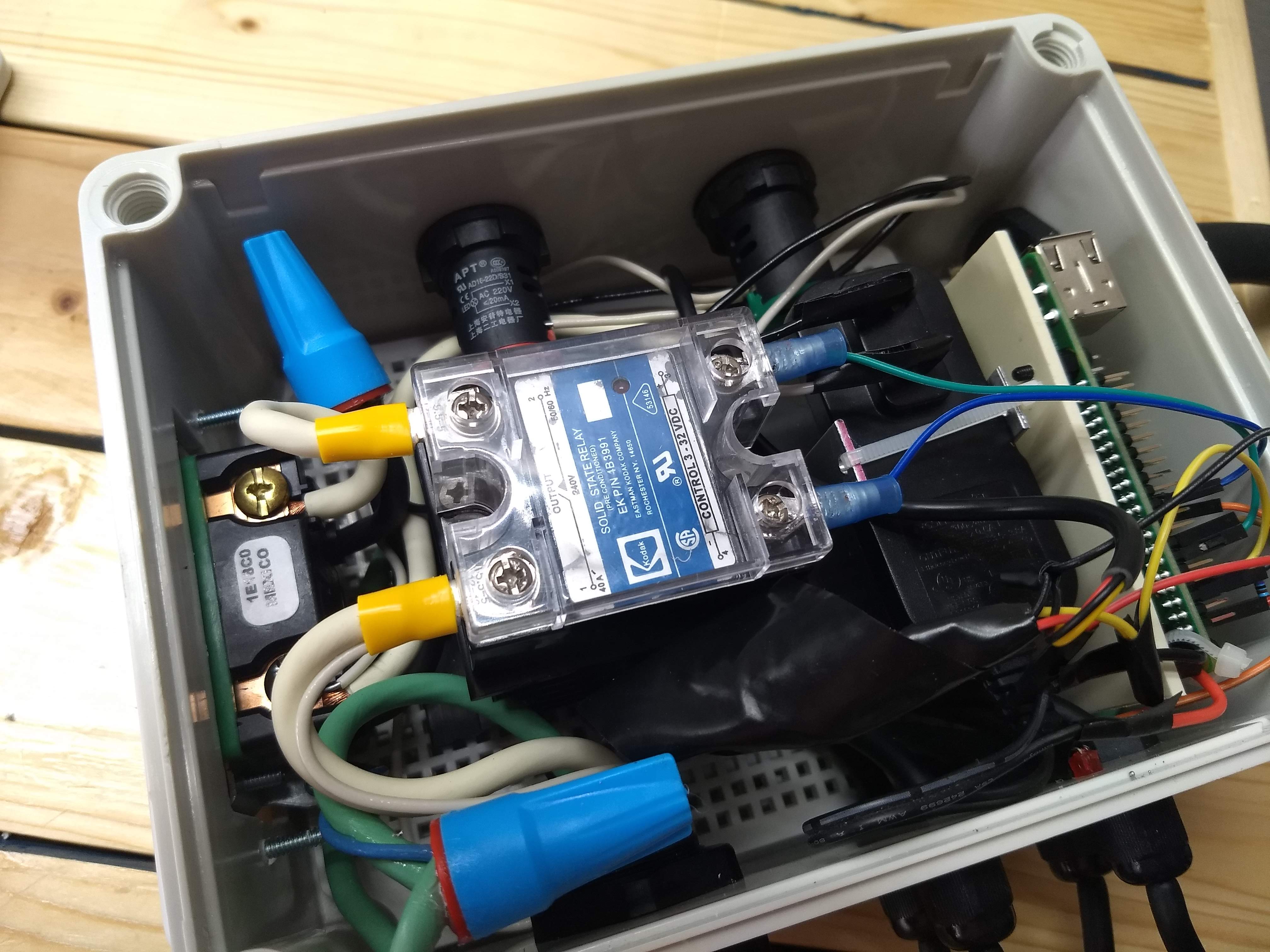

Sounds awesome!
My experience is that the cheaper the SSR the hotter it will get. Use thermal paste when you put it on the heat sink and allow adequate air circulation. At the end of the day some SSRs are built with under powered components so they'll forever try to over heat and stick in the on position.
Attaching the pigtail to the ground bar on the GFCI is not the recommended configuration.
If you don't bring that into the controller as a neutral I'm not sure that it's a problem from a safety standpoint, but I don't believe it's code compliant.
That never crossed my mind, I'll most likely be leaving them attached, but I'm interested to see if they are wired with the +5v on the plug tip!You need to be a little cautious using those 3 ring audio type plugs for your sensors. As long as your sensors are plugged in before the Pi is powered up they seem to work OK but a number of people over at the Craftbeerpi forum have reported that plugging them in while the Pi is powered will often crash the Pi and in some cases do permanent damage. I expect these issues are because those people didn't wire the plugs so the tip of the plug is the +5v so they were getting shorts when plugging in while the Pi was powered but it's something to keep in mind.
You need to put the PID into manual mode to control power during boiling. A PID algorithm cannot deal with a process that controls it's own temperature, like boiling does. In the manual mode you can set the power level to get whatever vigor of boil you desire (within reason.)What settings are you using for your heating element for mashing and boiling? I had thought I setup pid boil right but it just stayed on at 100% the whole time while boiling.

So there's a plugin called pidboil that should kick over to a manual mode once it gets above a certain temp, is there a different way to put craftbeerpi into manual mode?You need to put the PID into manual mode to control power during boiling. A PID algorithm cannot deal with a process that controls it's own temperature, like boiling does. In the manual mode you can set the power level to get whatever vigor of boil you desire (within reason.)
Brew on