Building a 240v 5500w Craftbeerpi Single Heating Vessel System (EBIAB?)

Homebrew Talk - Beer, Wine, Mead, & Cider Brewing Discussion Forum

Help Support Homebrew Talk - Beer, Wine, Mead, & Cider Brewing Discussion Forum:

This site may earn a commission from merchant affiliate links, including eBay, Amazon, and others.
Sounds good - I like the idea of testing it with a resistor.
It looks like it should trip if I connect a 47KΩ between the ground screw and the load side of the Levitron switch in the box ?

Will turning the switch on immediately trip the GFI ?
Use a 15 K ohm, or slightly smaller resistor.

A 47K ohm resistor may or may not work. at 120V, 47K ohms will only give you a 2.5 mA "leakage" current. A GFCI is not required to trip below 5 mA (I'm still trying to determine if that is the nominal, or upper spec limit), and is required not to trip below 1.9 - 2.0 mA. You also have to worry about the tolerance of the resistor. Most common resistors are +/- 10%, so your 47K resistor might be 51.7K, with a current of only 2.3 mA. Also, your voltage could be below nominal. If your "120V" was only 105V (during brown outs voltages can drop below 100V, IIRC), your test current might only be 105 / 51700 = 2.0 mA.

I'd recommend designing the test circuit to provide a minimum fault current of 6 mA under worst case conditions. 100V / 0.006A = 16.7K ohm. 15 K ohm is a standard resistor value that will be less than 16.7 K ohm even if it is at it's upper spec limit on tolerance.

What you really want to test is that the trip mechanism actually works, as it is the most likely failure point of the GFCI. Shift in trip limit is less likely, and also a less dangerous "fail" condition for the GFCI (as long as it stays under ~10 mA.) Also, testing the actual trip limit will require some precision measuring equipment ($$$.)

Brew on :mug:
 
At the risk of causing confusion.......


In a different thread when I asked a similar question for the heat element - a user named "itsnotrequired" posted this:
many gfci breakers need that neutral connection for the test button to function properly. the gfci will still function properly without the neutral, it is just the test button won't work. the problem is when there is NOT a neutral coming into the spa panel and folks start jumpering neutral to ground...

And this confirms the post that doug293cz mentions above.

So it appears that you really don't have to worry about it. Just DON'T connect your neutral and ground together in any sub-panel. The only place they can be tied are in the main panel in the house (or wherever the power from the electric company arrives).
Good point. Since the GFCI breaker (or any breaker) isn't wired to ground, the test circuit resistor cannot be connected to ground. Thus the resistor must be connected to neutral on the source side of the current sensing coil (if connected on the load side of the coil, the test circuit won't work.)

To get the "Test" button to work in a spa panel breaker, where there is no neutral coming from the main breaker, you should connect the pigtail from the GFCI breaker to the ground bus in the spa panel. This provides a completed current path for the test current to flow when the button is pushed. Do not connect anything to the load side neutral terminal of the GFCI breaker.

Brew on :mug:
I feel like I'm getting confused again..
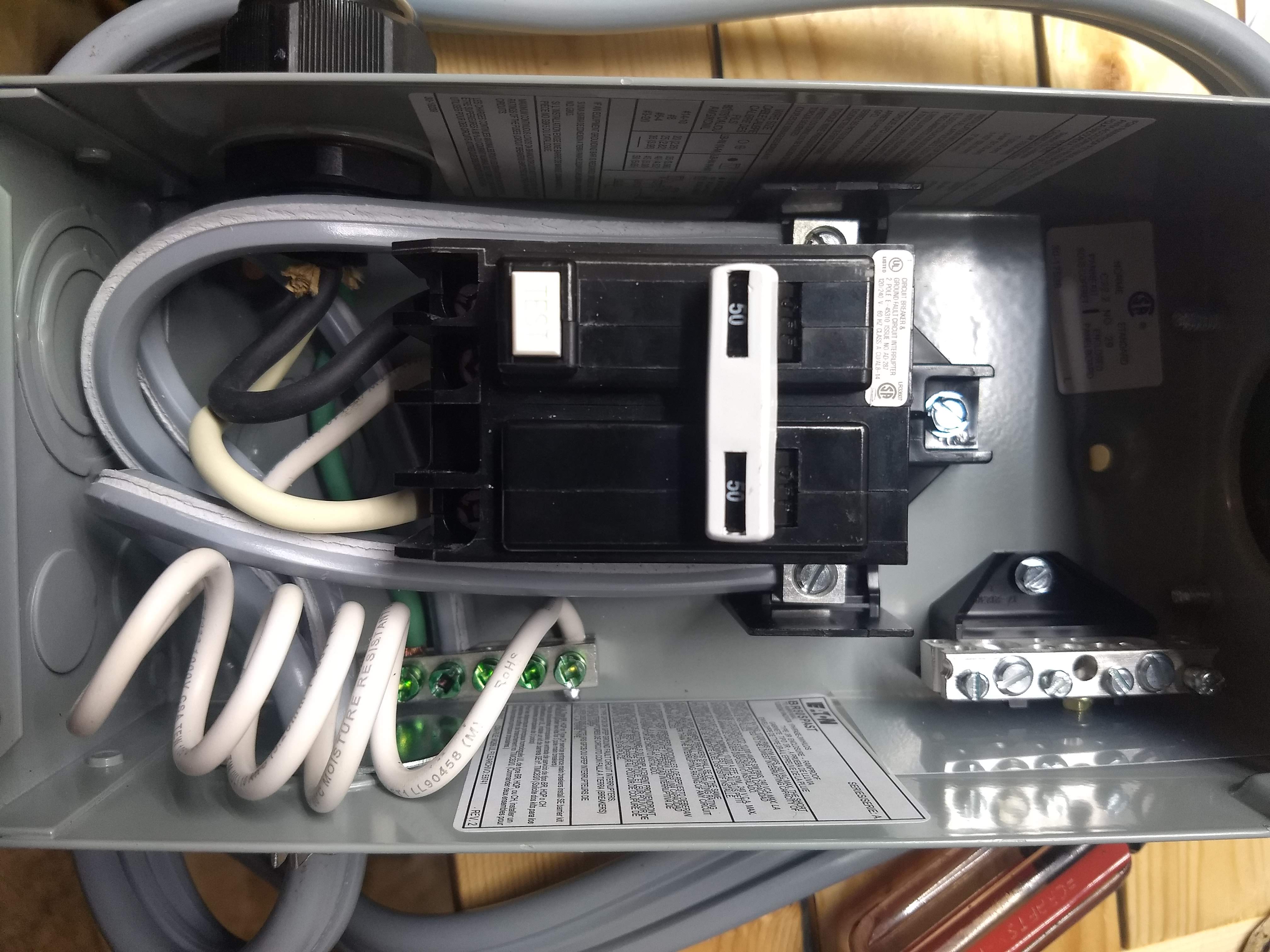
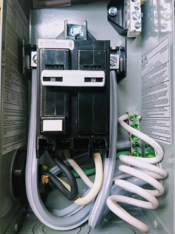
Is it correct that the two hot lines (in) should connect to the obvious places in the panel, the ground should go to the ground bus and then the two hot loads should go to either side of the breakers avoiding the one with the pigtail, and the pigtail should go to the ground bar ?

Like this ?

IMG_20190416_203509995~2.jpeg
 
I feel like I'm getting confused again..
Is it correct that the two hot lines (in) should connect to the obvious places in the panel, the ground should go to the ground bus and then the two hot loads should go to either side of the breakers avoiding the one with the pigtail, and the pigtail should go to the ground bar ?

Like this ?

View attachment 622472
Yes. Otherwise, the "Test" button on the GFCI breaker won't work.

Brew on :mug:
 
SUCCESS !!!!

I did a little last minute checking over last night and plugged it in for the first time today!!

Let's just say I was confident, but a little nervous. My first plan was to test the GFCI with a 20k ohm resistor (the closest one in my box) I soldered it to two small wires and attached one to the load of the switch and one to the ground screw. My son was excited to look over my shoulder and talk about it because he knows how much time I've spent on it. I had to explain the "expected" steps :

Insure all switches and breakers are off then :
1) Plug in cord from Spa Panel to wall
2) Turn on 30a breaker in main box
3) Turn on breaker in Spa Panel
4) Look for Green light indicating power in box
5) Flip Levitron switch on box on (that is attached to the resistor)
6) Spa Panel makes clicking sound (trips) and Green light goes off

Needless to say, perfect show. Then I reset everything to off, removed the resistor, turned the main breaker on and the Spa Panel on and pushed test. Tripped again ! Another win.

Now, I was finally ready to test a water heat up. Put water in the kettle, turned everything on, and was able to control the element remotely from Craftbeerpi. How cool, pretty silently heating water.

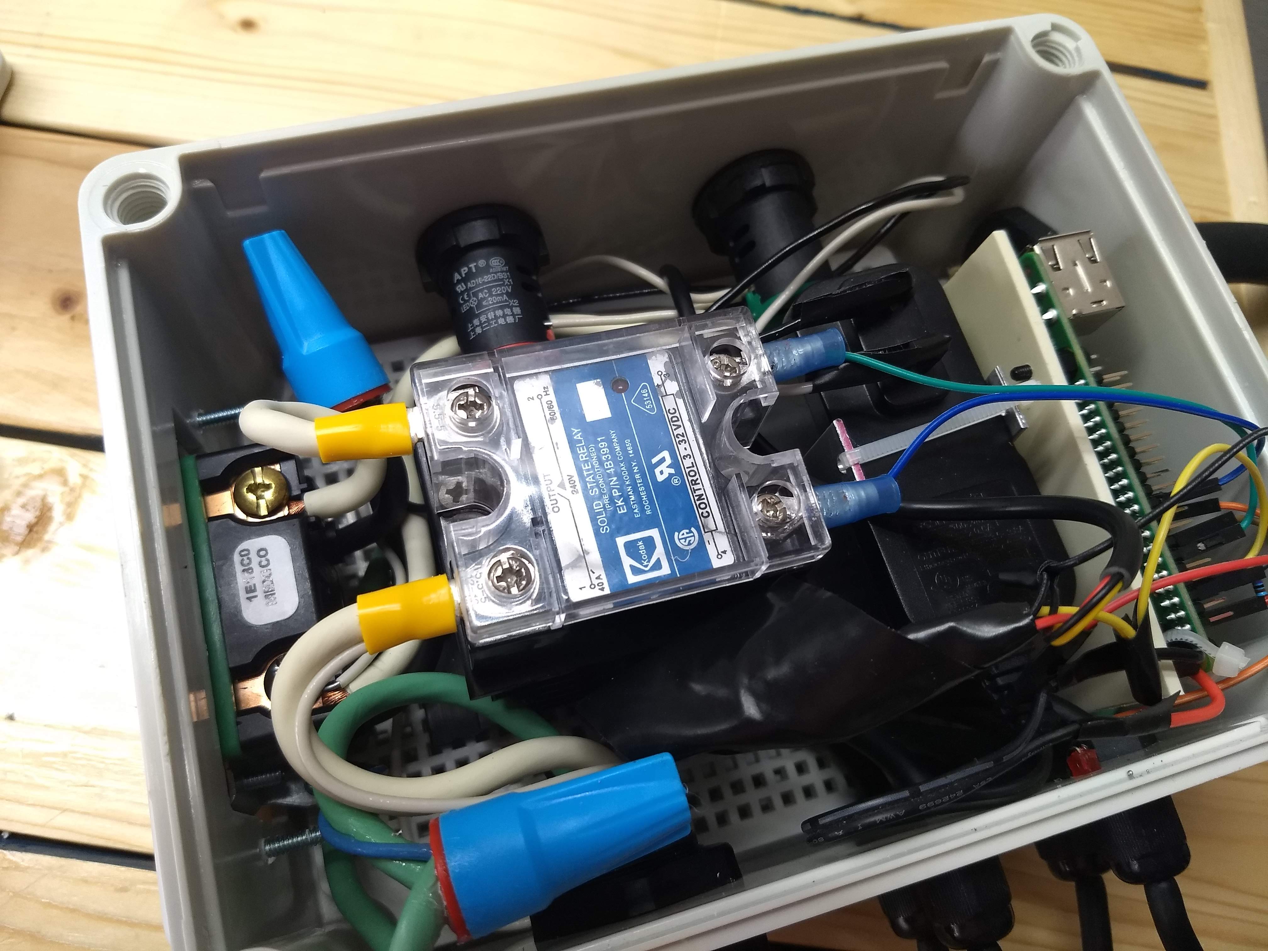
Unfortunately I overshot 170 and realized I couldn't turn the element off from the software - LUCKY I PUT A EMERGENCY SHUTOFF SWITCH IN (thanks to doug293cz) !! Flipped it off and realized that the temp inside the box was about 130F+. Time to install some fans or get that heatsink outside that box. I used too small of a box, but it looked cool, and totally underestimated how hot the SSR would get. If ventilation etc doesn't work, I'll be moving to a larger box - but with my newfound knowledge and plan, it'll be a lot less nerve racking.

Thanks so much to everyone for taking the time to comment on this thread, I hope that others will find it and be able to create a similar machine !

Pics to follow !

~Joey
 
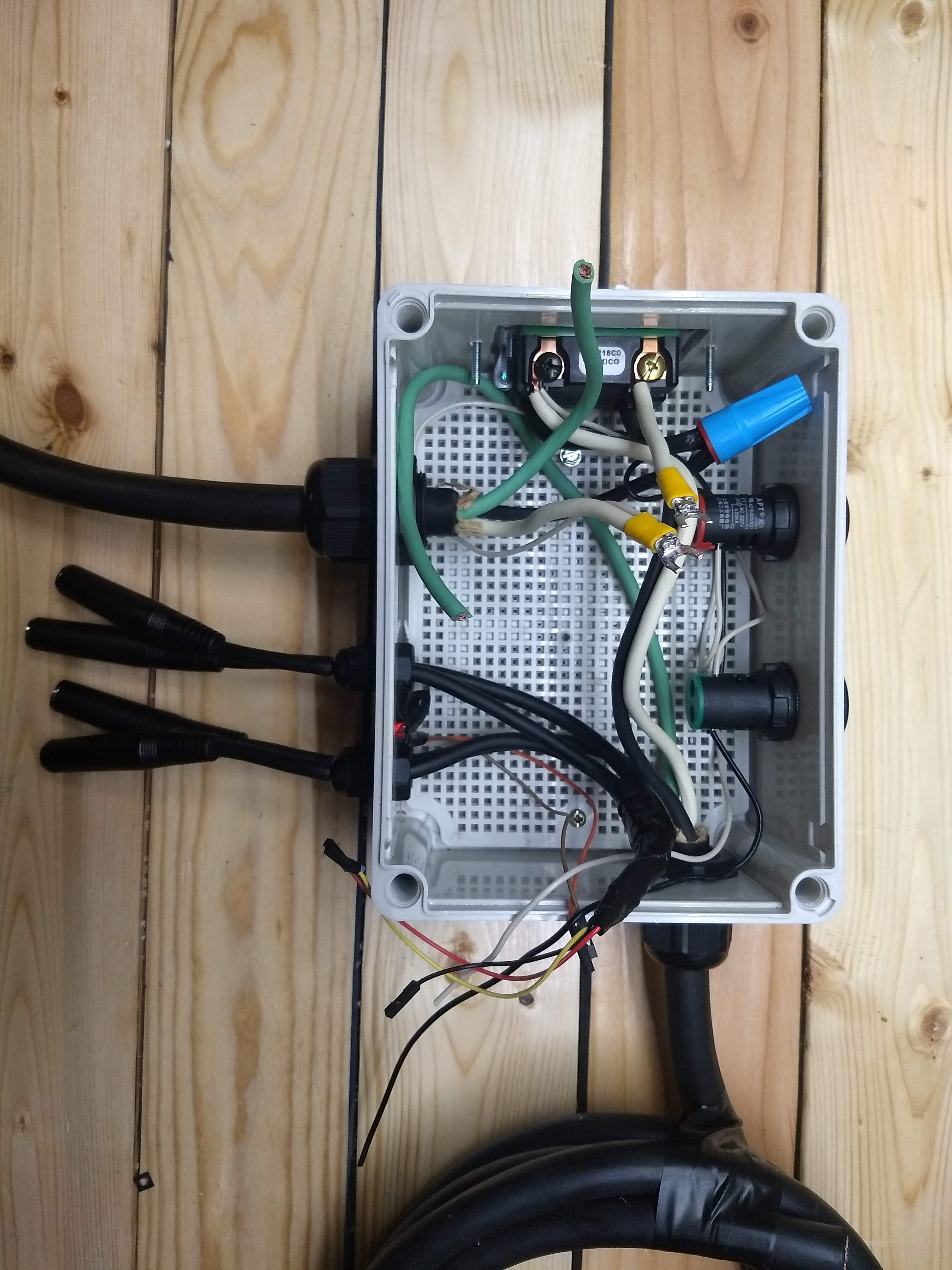
Just getting started wiring everything up - I opted for wirenuts because with one element there were only two or three wires being joined. I'm using four 1/4 three ring headphone cords for temp sensors, right between them you can see the remote LED indicator for the raspberry pi


IMG_20190410_212735966.jpg


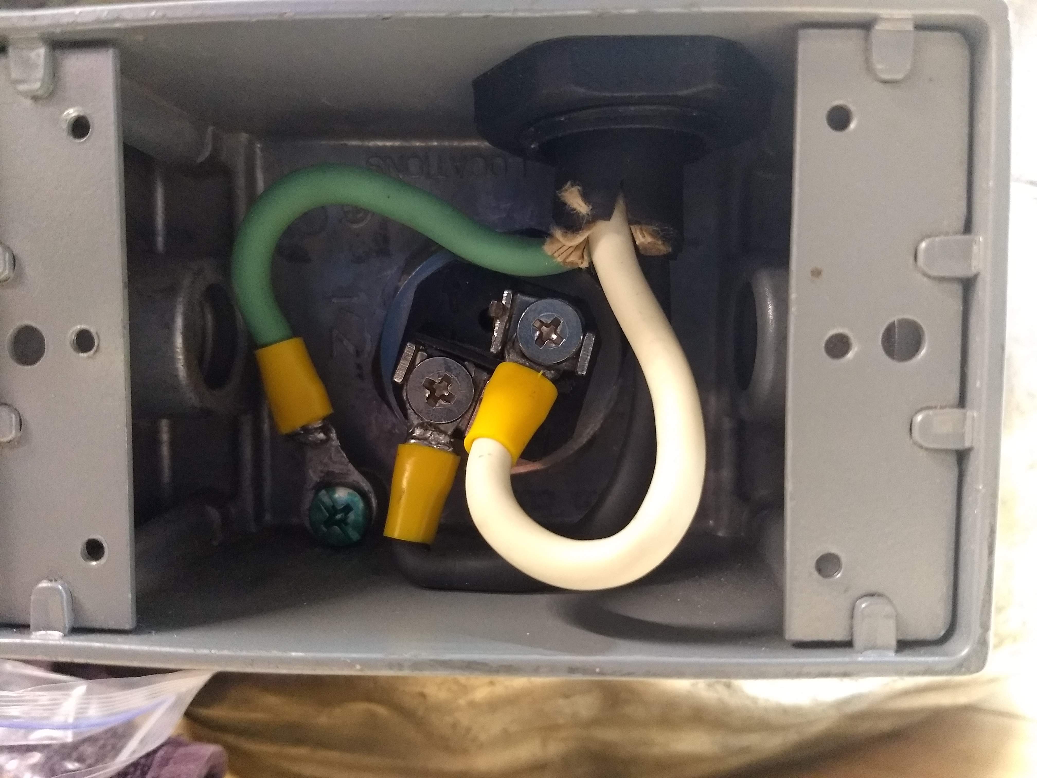
This is inside of the element enclosure. It's solid metal and I had a nut welded onto the outside of the kettle, I drilled a hole in the enclosure, used a bit of a silicone mat cut to fit for a gasket and wired these up. I soldered on all of the connections and have gotten MUCH better at soldering on this project.

IMG_20190414_212254223.jpg


Spa panel wired for a three wire connection - Hot Hot Ground

IMG_20190416_203509995.jpg


This is the resistor to test the Spa Panel, it's not connected to the ground screw yet !
IMG_20190416_214524573.jpg


Damn the box is crowded no wonder it's getting hot in here.
IMG_20190417_170219789.jpg


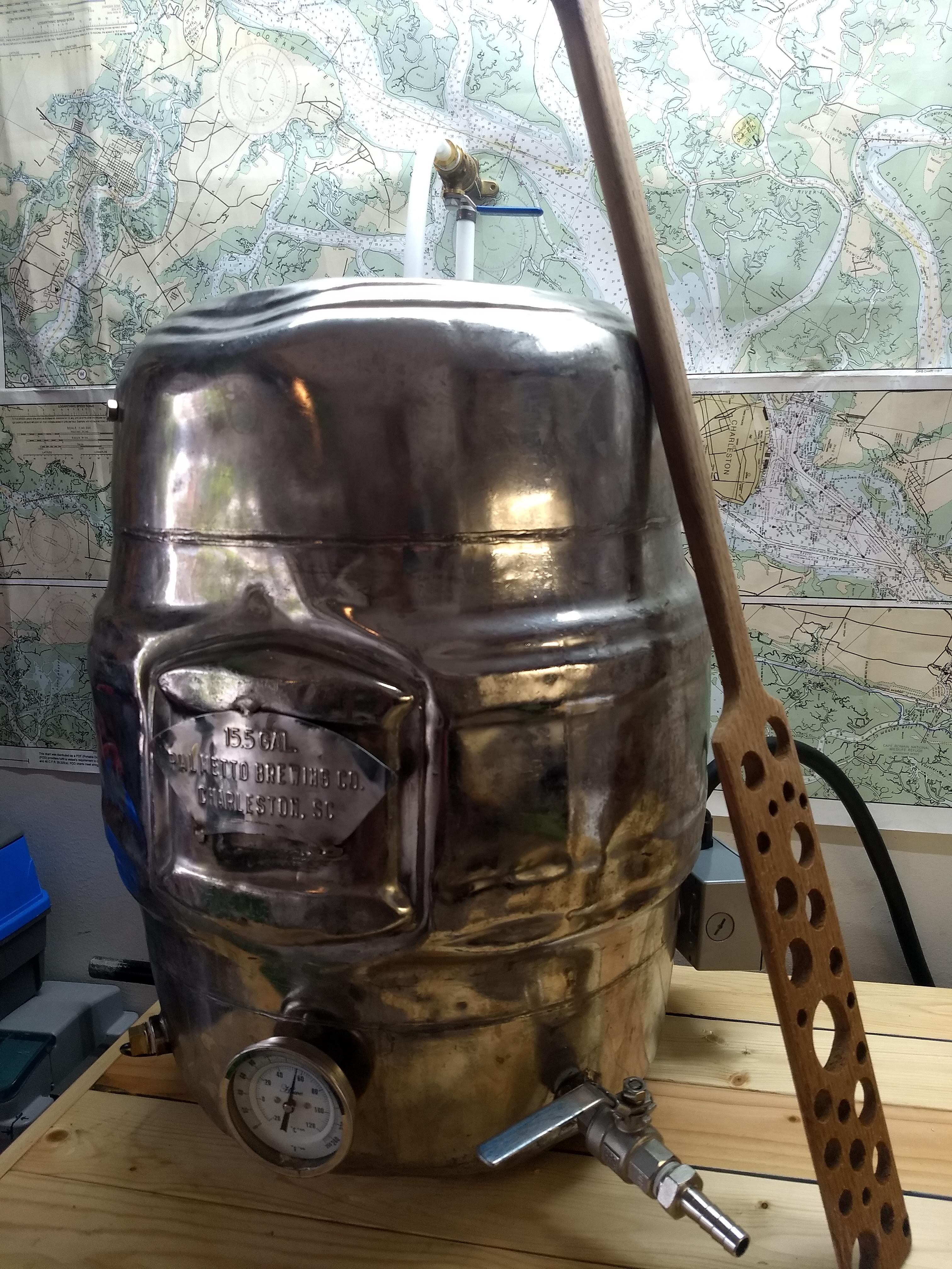
Here's the finished E-Keggle (actually E-Firkin) I've had it for about 10 years, and brewed every batch of beer I've ever made in it !! It was a gift from a buddy at Palmetto Brewery
IMG_20190417_181929746.jpg
 
Last edited:
Sounds awesome!

My experience is that the cheaper the SSR the hotter it will get. Use thermal paste when you put it on the heat sink and allow adequate air circulation. At the end of the day some SSRs are built with under powered components so they'll forever try to over heat and stick in the on position.

If I can't get it to stop with a couple of fans and thermal paste, I'll definitely replace it. It says it was made by Kodak in Rochester, which I thought was cool, but I may be able to get a much better one. It's been on a shelf for years
 
Attaching the pigtail to the ground bar on the GFCI is not the recommended configuration.

If you don't bring that into the controller as a neutral I'm not sure that it's a problem from a safety standpoint, but I don't believe it's code compliant.
 
Attaching the pigtail to the ground bar on the GFCI is not the recommended configuration.

If you don't bring that into the controller as a neutral I'm not sure that it's a problem from a safety standpoint, but I don't believe it's code compliant.

Good eye !
I didn't bring it into the panel as a neutral. We talked about it a few posts back and doug293cz suggested it only to make the test button on the panel work. The test button does work, someone had said it wouldn't if it was just mounted to the neutral bar to keep it from flopping around.
 
You need to be a little cautious using those 3 ring audio type plugs for your sensors. As long as your sensors are plugged in before the Pi is powered up they seem to work OK but a number of people over at the Craftbeerpi forum have reported that plugging them in while the Pi is powered will often crash the Pi and in some cases do permanent damage. I expect these issues are because those people didn't wire the plugs so the tip of the plug is the +5v so they were getting shorts when plugging in while the Pi was powered but it's something to keep in mind.
 
You need to be a little cautious using those 3 ring audio type plugs for your sensors. As long as your sensors are plugged in before the Pi is powered up they seem to work OK but a number of people over at the Craftbeerpi forum have reported that plugging them in while the Pi is powered will often crash the Pi and in some cases do permanent damage. I expect these issues are because those people didn't wire the plugs so the tip of the plug is the +5v so they were getting shorts when plugging in while the Pi was powered but it's something to keep in mind.
That never crossed my mind, I'll most likely be leaving them attached, but I'm interested to see if they are wired with the +5v on the plug tip!
 
All is well in paradise ! 4 BIAB batches in the new kettle and a sous vide steak night for the wife - best steak I've ever cooked !!

I've added a chest freezer beside the control panel and run it with an STC-1000 which is going well.

I was wondering - is there any harm in leaving the 220v spa panel powered on, with the emergency shutoff turned off - just to get the pi powered with a sensor in the fridge (to chart the temp changes) or should I just leave well enough alone and trust the offline sensor ?

As always, y'all are amazing !

Joey
 
I leave my controller on 24/7. Not going to hurt anything if the wiring is safe, but it's not protected from a power surge.
 
What settings are you using for your heating element for mashing and boiling? I had thought I setup pid boil right but it just stayed on at 100% the whole time while boiling.
 
What settings are you using for your heating element for mashing and boiling? I had thought I setup pid boil right but it just stayed on at 100% the whole time while boiling.
You need to put the PID into manual mode to control power during boiling. A PID algorithm cannot deal with a process that controls it's own temperature, like boiling does. In the manual mode you can set the power level to get whatever vigor of boil you desire (within reason.)

Brew on :mug:
 
You need to put the PID into manual mode to control power during boiling. A PID algorithm cannot deal with a process that controls it's own temperature, like boiling does. In the manual mode you can set the power level to get whatever vigor of boil you desire (within reason.)

Brew on :mug:
So there's a plugin called pidboil that should kick over to a manual mode once it gets above a certain temp, is there a different way to put craftbeerpi into manual mode?
 
In manual mode, 80% produces a really vigorous boil ~2g per hour boiloff. I'm going to try 40% next brew day.
I have the heater set up in hystersis mode and it turns on and off and holds temps pretty well. I couldn't find the PID setup mode, and it's worked fine as is so far
 
In manual mode, 80% produces a really vigorous boil ~2g per hour boiloff. I'm going to try 40% next brew day.
I have the heater set up in hystersis mode and it turns on and off and holds temps pretty well. I couldn't find the PID setup mode, and it's worked fine as is so far
Ah okay, are you doing anything to hold the mash temps? Or are you just heating the strike water manually and then leaving the mash alone?
 
With the hystersis setting, I just set the target temp and the little car (auto lol) and it holds it pretty close. It does tend to overshoot a couple of degrees and then creep back down. I've been setting it about 2-3* lower than I want to mash.

I'd be interested to hear how to set up the PID and if it could get it to hold closer. I've also considered just insulating and shutting it off...
 
I should also mention I'm using Craftbeerpi3.0 !
So there's two plugins you can add from the plugin tab, pidautotune and pidboil. Then after a restart they are available for the heater logic.

with pidautotune you add your typical water amount, and it runs and trys to maintain temperature for awhile then it gives you the PID values. You then change the heater to pidboil and add those values in. Then pidboil is setup with a boil threshold where it changes from pid to manual supposedly, and you can set the mwc boil output.

I'm going to try it out in a batch tomorrow, on my first batch I think I had some settings messed up and it just boiled at 100% the whole time.
 
I'm back at it again !
After 7 successful brews, I decided to upgrade to a bigger case with more ventilation. The SSR got stuck on a couple of times and I rigged up some fans etc, but it was a mess. I'm midway through moving it to a recycled computer case, it's a thing of beauty.
The computer power supply has 220 input, and 12v and 5v outputs, just what I needed for the pump and pi.

While I'm at it, I'm going to upgrade the Levitron switch with a Estop and contactor.
I can't seem to find a drawing with a 3 wire 220 and a contactor. ( I understand how the two hots run through the contactor)

Should the hot wire go to one side of the estop then to the side post of the contactor ?
Since there's no neutral, does ground go to the other side post of the contactor ?


Also, I was thinking of putting the contactor after the SSR, just to kill the element and leave the power on to the panel and computer.
Is that a bad idea ?


Thanks again for all your help !
 
Also, I was thinking of putting the contactor after the SSR, just to kill the element and leave the power on to the panel and computer.
Is that a bad idea ?
If the controller/computer is what's on fire and smoking, putting the contactor AFTER the SSR but before the heat element won't gain you a whole lot. I'd put it before the SSR.
 
I'm back at it again !
After 7 successful brews, I decided to upgrade to a bigger case with more ventilation. The SSR got stuck on a couple of times and I rigged up some fans etc, but it was a mess. I'm midway through moving it to a recycled computer case, it's a thing of beauty.
The computer power supply has 220 input, and 12v and 5v outputs, just what I needed for the pump and pi.

While I'm at it, I'm going to upgrade the Levitron switch with a Estop and contactor.
I can't seem to find a drawing with a 3 wire 220 and a contactor. ( I understand how the two hots run through the contactor)

Should the hot wire go to one side of the estop then to the side post of the contactor ?
Since there's no neutral, does ground go to the other side post of the contactor ?


Also, I was thinking of putting the contactor after the SSR, just to kill the element and leave the power on to the panel and computer.
Is that a bad idea ?


Thanks again for all your help !
You cannot use a contactor with a 120V coil in a panel without a neutral. If you wired a hot and ground to a 120V coil, you would trip your GFCI as soon as you applied power to the coil. You must use a contactor with a 240V coil.

Use the schematic below as a guide. You can leave out the volt/amp meter. The e-stop switch should be a double pole, normally closed device, and should be located between the 1A fuses and the key switch, and should be wired just like the key switch. In my opinion the e-stop switch is redundant, since you can kill power just as easily with the key switch. But, if you want to put it in, there is no issue with doing so.

DSPR120 1 - Element 0 - Pump Volt-Amp Meter 240V only.PNG


Brew on :mug:
 
Thanks for the help again Doug293cz ! I'll study that drawing.
Hot 1 to one side of the coil, and Hot 2 to the other makes more sense than getting ground involved. I guess only one would have to go through the E-Stop switch ? This is the switch I'm using : https://amzn.to/2K0iwb0

The contactor is a 240v 30amp (as best as I can tell) - pictured below.
img_20190324_142903689-2-jpeg.618979
Yes, since that switch has one NO contact pair, and one NC contact pair, you can only run one hot thru the NC side of the switch. This will work as an e-stop. However, best design practice is to use two NC pairs in a switch so that both hots are disconnected when activated.

As @golfindia noted, the contactor pictured has a 120V coil, so cannot be used in a system without a neutral.

Brew on :mug:
 
As a side note. An E-Stop button with 2 NC blocks is strangely expensive. It seems to be cheaper to buy two of the Uxcel buttons and scavenge one of the switch blocks.
 
I'm back at it again after getting side tracked on another project.
I already have the Uxcel button installed, is there any point to just wiring one side of the coil to hot1, and running hot2 to the Uxcel switch and back to the coil ?

Hitting the estop would kill all power past the contactor and the only things hot would be one side of the coil and the transformer for 12v etc that's wired before the contactor.

There is also this switch on Amazon that has 2 NC if the above is unsafe. hot1 and hot2 will still be live going to that switch though?
 
Last edited:
Pleased to say I got it figured out! I stopped by our wholesale industrial electronics in Charleston, and got just the right switch for $30! 2 pole 220 volt 10 amp Siemens switch, it's a thing of beauty compared to the Chinese plastic one that I had
 

Latest posts

Back
Top