Building a 240v 5500w Craftbeerpi Single Heating Vessel System (EBIAB?)

Homebrew Talk - Beer, Wine, Mead, & Cider Brewing Discussion Forum

Help Support Homebrew Talk - Beer, Wine, Mead, & Cider Brewing Discussion Forum:

This site may earn a commission from merchant affiliate links, including eBay, Amazon, and others.

joeybeer

Well-Known Member
Joined
Dec 13, 2009
Messages
567
Reaction score
26
Hi all,
I've been thinking about this build for what seems like 10 years ! Long enough, that my dreams of PID control have been replaced by the amazing Craftbeerpi. We moved into a new house recently, and when I removed a cover plate off the wall behind my work bench, what should I find but a cluster of capped 30amp 240v wires. Talk about a dream come true.

So I'm ordering parts and scratching my head. I have a good understanding of how the Craftbeerpi works and the GPIO temp sensors etc. I just need some help figuring out how to wire up the rest of the panel.

Ideally I'd like :
An emergency shutoff (this is going to be within reach of a spa panel though)
A light showing power to the box
A light showing power to the element
Always on 120v inside the box to plug in a wall wart for 12v power (for small pump) and 5v power for the pi. **Unless there's a better way

Other than that, I'll control everything remotely - if it stays cool enough, I'll keep it closed - if it needs a fan, I'll keep it away !

My other lingering question is how to connect the wires in the wall (only about 6" long) to the spa panel, and can I mount a L14-30 style receptacle on the outside of the spa panel ? Is there usually a plug between the panel and the wall ?

Thanks so much for any help ! I'll be sure to document the build for future builders.

Also, in reading about EBAIB so much, because it's pretty similar, I think I have a odd way of brewing. I heat my strike water in the kettle, mash in a cooler, then drain into a bucket while the sparge water stays warm in the kettle. Then after the sparge I have 3 2gallon buckets of wort to put in the empty kettle for the boil. It's like the two cooler system, but keeping the water at temp in the kettle and using buckets. Anyway, it works well for me and there's nothing too heavy to lift !
 
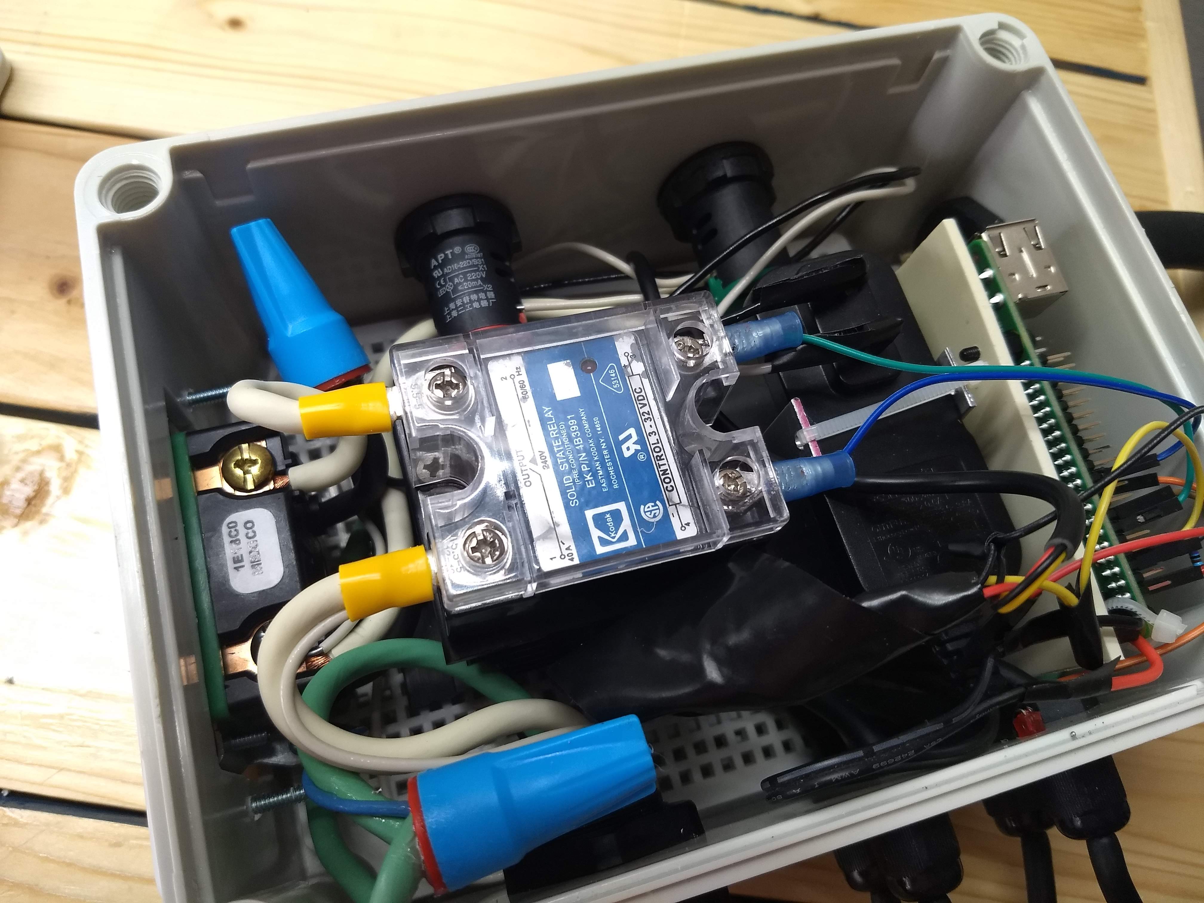
I'm building my panel and ebiab kettle now, might not be the best example, but I've got a partlist and some build photos, doesn't turn on right now so I'll have to take it all apart and figure out what went wrong, but eventually I'll have an example of what not to do.

https://www.homebrewtalk.com/forum/threads/switching-to-ebiab.661958/
I was definitely reading your thread too, don't get discouraged! You'll get it figured out in the end, there are some amazing people on here.

Just watch people filling up propane tanks for a while, that'll cheer you up! [emoji23]
 
Hi all,
I've been thinking about this build for what seems like 10 years ! Long enough, that my dreams of PID control have been replaced by the amazing Craftbeerpi. We moved into a new house recently, and when I removed a cover plate off the wall behind my work bench, what should I find but a cluster of capped 30amp 240v wires. Talk about a dream come true.

So I'm ordering parts and scratching my head. I have a good understanding of how the Craftbeerpi works and the GPIO temp sensors etc. I just need some help figuring out how to wire up the rest of the panel.

Ideally I'd like :
An emergency shutoff (this is going to be within reach of a spa panel though)
A light showing power to the box
A light showing power to the element
Always on 120v inside the box to plug in a wall wart for 12v power (for small pump) and 5v power for the pi. **Unless there's a better way

Other than that, I'll control everything remotely - if it stays cool enough, I'll keep it closed - if it needs a fan, I'll keep it away !

My other lingering question is how to connect the wires in the wall (only about 6" long) to the spa panel, and can I mount a L14-30 style receptacle on the outside of the spa panel ? Is there usually a plug between the panel and the wall ?

Thanks so much for any help ! I'll be sure to document the build for future builders.

Also, in reading about EBAIB so much, because it's pretty similar, I think I have a odd way of brewing. I heat my strike water in the kettle, mash in a cooler, then drain into a bucket while the sparge water stays warm in the kettle. Then after the sparge I have 3 2gallon buckets of wort to put in the empty kettle for the boil. It's like the two cooler system, but keeping the water at temp in the kettle and using buckets. Anyway, it works well for me and there's nothing too heavy to lift !
For the Spa panel to the wall power I would simply put the panel over that outlet you uncovered and wire it directly in. I would use a 4-prong range/dryer receptical at the spa panel to plug the controller into.

I used pre-made cords with the plugs in them to save money and they work great.

For the indicator lights I went with these. They work great and look professional. https://www.amazon.com/dp/B01M6WULBK/ref=cm_sw_r_cp_apa_i_bW6LCb1CZR5VM

You can also get them in 240.

For the shut off I'm guessing you'd like the look of an e-stop which I agree looks cool.
https://www.amazon.com/dp/B00SDX0GD2/ref=cm_sw_r_cp_apa_i_KZ6LCb97WE556

The best approach is to use a switch like this to turn a larger contactor on and off
https://www.amazon.com/dp/B001KGSJ74/ref=cm_sw_r_cp_apa_i_j16LCb93NWGX6


For the 5v / 12v inside you could simply wire a normal house outlet inside the box and plug in a power supply, or you could get a dedicated power supply.
https://www.amazon.com/dp/B074YHN8D1/ref=cm_sw_r_cp_apa_i_L46LCb0QCP3VR
https://www.amazon.com/dp/B07HD29494/ref=cm_sw_r_cp_apa_i_Ob7LCbN6X49TQ

Finally, regarding the heat, the SSR is going to need a heat sink, lots of options for that, and a little fan might help to keep things even more cool. Since you have a rPi you could put an extra ds18b20 inside the enclosure to see how hot things are actually getting.
 
Great tips Beardedbrews - I think we have similar tastes in cool looking lights and switches.
I have a contactor, but no idea how to wire it up to the E-stop (I'll post a pic of it this afternoon) and I agree with the household outlet inside the box with the adapters in there (no idea how to wire that up either !)

Thanks for the links, I'll definitely order those lights and the E-stop !
 
You get colored pencils since it's what I had.

If you use the Normally Closed side of that e-stop it will be "on" when it's up and cut off as soon as you hit the button. You could use the button instead of the main on/off switch if you wanted.

As far as the outlet inside the box, you could go a couple different ways. One fairly clean approach would be to buy a power strip like this.
https://www.amazon.com/dp/B071KCVFDQ/ref=cm_sw_r_cp_apa_i_0b8LCbA07K6K4

You cut the plug off and connect the wires directly to Hot/Neutral/Ground anywhere convenient inside the enclosure.
1553448801707.jpeg
 
You get colored pencils since it's what I had.

If you use the Normally Closed side of that e-stop it will be "on" when it's up and cut off as soon as you hit the button. You could use the button instead of the main on/off switch if you wanted.

As far as the outlet inside the box, you could go a couple different ways. One fairly clean approach would be to buy a power strip like this.
https://www.amazon.com/dp/B071KCVFDQ/ref=cm_sw_r_cp_apa_i_0b8LCbA07K6K4

You cut the plug off and connect the wires directly to Hot/Neutral/Ground anywhere convenient inside the enclosure.View attachment 618971
Here's a picture of the contactor I have, do I need one for each hot or will both hots go through it ?
IMG_20190324_142903689~2.jpeg
 
I used a blue 12v indicator lamps for my 12v pump like this: https://www.ebay.com/itm/LED-Indica...hash=item21296fa21f:m:mKaprd5cqY_uIQGUd3zrE3Q
A red 240v indicator lamp for the the heater. at the same link (choose color and voltage). You can use a 120v lamp if you have an AC pump.

Red for heat, blue for pump/cool. Run them right off the same source going to the heat element and pump so they are lit when the circuit is actually energized....not on the control for the circuit.

I also used the Terragady board to have 12v on the control circuits, since I read that some of the knockoff SSRs need more than the 3v the Raspberry Pi puts out. With the 12v control, there's no question.

I didn't go with the emergency shutoff since everything is right next to each other in my garage/brew-house. Both the sub-panel with breaker and spa-panel with breaker right next to the Craftbeerpi Controller Box.

I used 1/4" stereo Jacks and plugs for my temp sensors. The jacks are locking, so the plugs won't fall out. 3-terminals built in with Ground, tip and ring.

I have a 12v wall-wart power supply powering the Terragady 12v board, which has a 5v regulator on it to power the Raspberry Pi. The Jack on the outside of the box. The 12v also powers my pump and related 12v circuit/relay/lamp.

I also added an alarm on mine. It came in a kit of Arduino project parts. Something like THIS.

Here's a decent guide to wiring Spa Panels.
The Neutral and Ground are never tied together in any sub- or spa-panel. Only in the main box in the house should the neutral and ground be connected together.
The link just above will show you a diagram based on whether you have 3-wire or 4-wire source.

spa-panel-wiring-png.417521
 
Here's a picture of the contactor I have, do I need one for each hot or will both hots go through it ?View attachment 618979
Both hots go thru a single contactor like that. Both feed connections on one end, and both load connections on the other end. You connect the switched hot wire on one of the sides at 90 deg to the high amp connections, and connect neutral on the opposite side.

Brew on :mug:
 
Both hots go thru a single contactor like that. Both feed connections on one end, and both load connections on the other end. You connect the switched hot wire on one of the sides at 90 deg to the high amp connections, and connect neutral on the opposite side.

Brew on :mug:
I don't yet have a layout - I plan to start with an existing one and try to remove components.. where does the switched hot come from ? I also don't know where to get the 120v power from for the always on outlet inside the box. The Pi I have figured out though, three temp sensors and a power on led are working fine. I also picked up the length of SOOE cable that I plan on using between the control box and element - is it OK to use that on the 3 foot run between the spa panel and the control box or should that be solid core?

Thanks so much for the advice, I feel like I'm making progress !
 
Last edited:
I've been missing - busy the last couple of days installing an electric dog fence, burying line in the yard is MUCH less fun than brewing beer !!

@doug293cz - any chance you could help me out with a diagram or point me to a sketch of a controller with a E-stop - Contactor - SSR - Kettle - always on 120 plug - with a "controller power on" light and a "kettle power on" light ? I'm pretty sure I can take if from there.

After 100 plus propane brews, it's exciting to imagine brewing a batch without having to babysit a flame !!
The diagram below has most of what you want. For the e-stop, just add an NC mushroom switch between the 1A fuse and the key switch. For an always on outlet, just eliminate the switch shown for the outlet.

DSPR310 1-Pump 240V  eBIAB.PNG


Brew on :mug:
 
Thanks so much for your advice !! I have a couple of crazy days at work and then I'll find time to look over this and keep y'all updated !
 
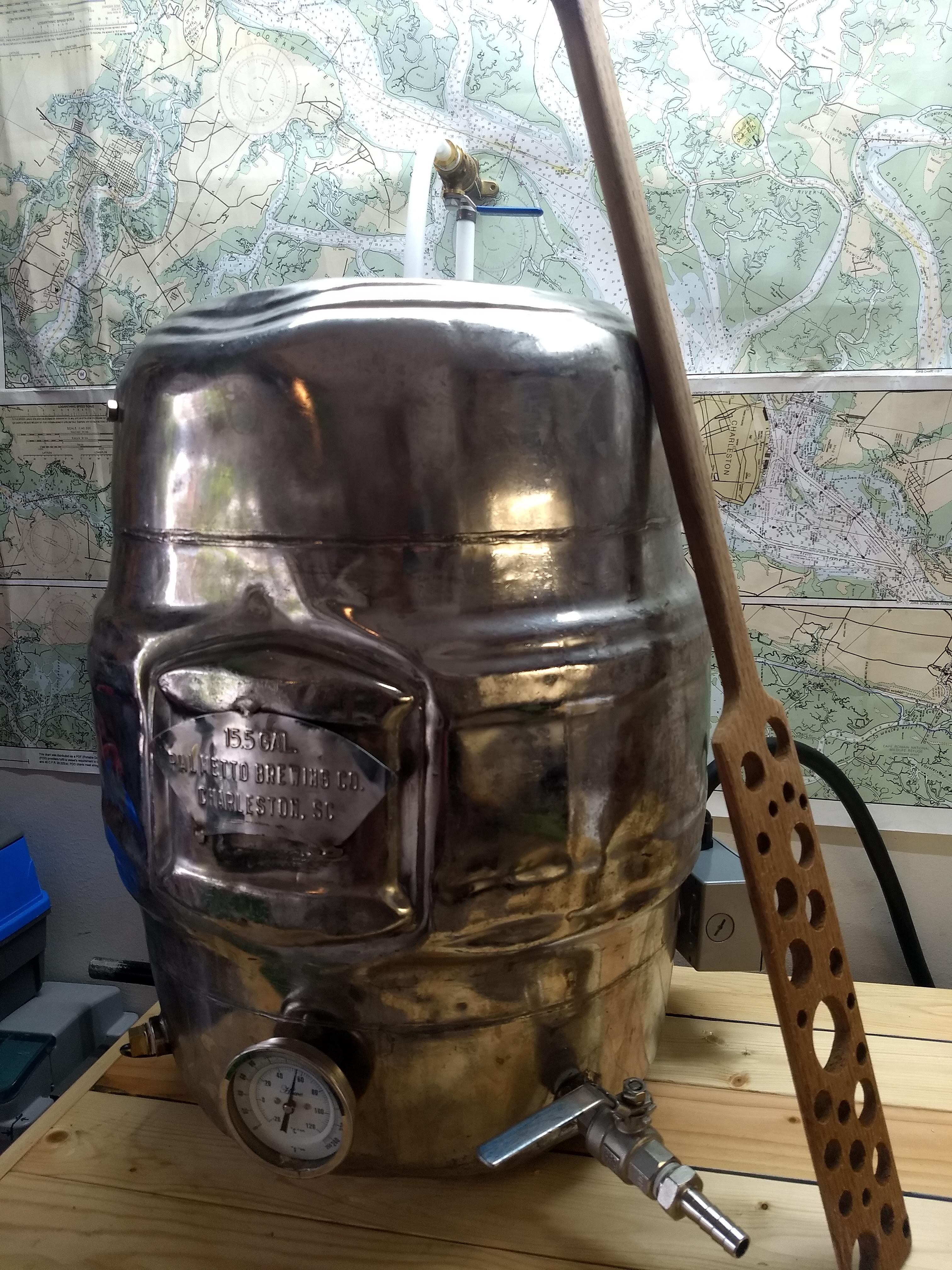
Alright, I've spent a few hours working on this project this weekend, I've got the Pi in the box, and the element in the enclosure and the nut welded on the kettle, now I'm just waiting for a couple of new orings and a sightglass from brewhardware and I'll be nearly ready to go.

EXCEPT for actually wiring the control box o_O
I seem to have spent the best part of today avoiding looking at wiring diagrams and figuring out what else I need to do...

So I've finally started looking at a really simple diagram that even I can understand and think it looks like a starting point. I've seen posters commenting on skipping the e-stop if they can reach the panel, and that seems to be one of my last questions. I'll have a light so I'll know if the SSR is stuck on and could just reach over to the spa panel and kill it. (I think ?)

Let me know what you think of this and any recommendations on bus bars vs wire nuts or something similar for these really simple connections.

full
 
There is almost no reason to skip a hard disconnect at the element. At a minimum it gives you peace of mind when you're plugging and unplugging stuff. "I don't really need one since I can just grab the cord and unplug it or flip open the spa panel" is bad logic, design this so it will be clear to your drunk friend how to make it turn off.

A basic Leviton 30a light switch would work just fine. A contactor would be a clean solution too if you've got space in the box and don't mind a little extra wiring.
https://www.amazon.com/dp/B002MPPTBQ/ref=cm_sw_r_cp_apa_i_dORQCbCJ4R1BX
20190408_115855.jpg
 
Oh, and that light will tell you if your whole control box has power, not just the element. It's not going to tell you anything about the SSR status. You may mean another LED that you don't have shown in the diagram though.


Wire nuts work just fine and are safe, feel free to use those if you prefer.
 
@BeardedBrews comments are spot on. Here's a diagram for a simple controller that has a proper disconnect switch, and a light that will tell you if the SSR is working correctly. You just need to replace the DSPR with your RPi based controller.

DSPR120 1-Element  240V only.PNG


Brew on :mug:
 
Thanks so much guys - although it's taken me a min, it's starting to make sense now.
I was feeling like I didn't know what I didn't know.

With the Levitron 3032 switch above, I'm having a hard time imagining how it cuts power to both leads at once. After a few more mins thinking about it, it makes more sense, and red would go to the top pole and black to the bottom ?
 
Last edited:
Thanks so much guys - although it's taken me a min, it's starting to make sense now.
I was feeling like I didn't know what I didn't know.

With the Levitron 3032 switch above, I'm having a hard time imagining how it cuts power to both leads at once. do you just join red and black then attach to one pole and the red and black combined to the other ? (I think that's what the dotted line in the switch is indicating)
Something like this dual pole switch I think would switch both lines. https://www.homedepot.com/p/Leviton...ble-Pole-Switch-White-R62-03032-2WS/100356941
 
Thanks so much guys - although it's taken me a min, it's starting to make sense now.
I was feeling like I didn't know what I didn't know.

With the Levitron 3032 switch above, I'm having a hard time imagining how it cuts power to both leads at once. do you just join red and black then attach to one pole and the red and black combined to the other ? (I think that's what the dotted line in the switch is indicating)
The 3032 is what's known as a double pole switch. It is actually two switches in a single package. One hot goes thru one switch, and the other hot goes thru the other switch. The dotted line indicates that the two switches are tied together mechanically, so that both switch at the same time.

Brew on :mug:
 
Thanks so much guys - although it's taken me a min, it's starting to make sense now.
I was feeling like I didn't know what I didn't know.

With the Levitron 3032 switch above, I'm having a hard time imagining how it cuts power to both leads at once. After a few more mins thinking about it, it makes more sense, and red would go to the top pole and black to the bottom ?
Everyone had to learn somewhere, it gets easier as you go.

A picture of the back of the switch might help.
20190408_132914.jpg
 
That makes sense now too !
Thanks so much for your help guys (and all your patience)
I'm sure I'll be quietly warming water in just a week or two at this rate :)
 
Late home from work today, mainly fooling with getting the keggle squared away tonight. I did have a look at the 220 wire in the wall and it's just 3 wires (white black and ground) I assume that a 4th wire or likely the whole thing would have to be pulled to the panel before I put the spa panel on top if I wanted 120v in the controller box ?

Has anyone just shoved a 240-120v laptop charging cable and a buck converter to get down to 5v (for the raspberry pi) in the controller box ? Could you just wire both hots to the wires on the input of the charger ?

Looking forward to your responses as always !

Joey
From what I encountered. building my set up, you'll need 4 wires so the 120 has a neutral and a ground. But I'm no electrician. Probably best for Doug or bearded to answer that question.

As for the raspberry pi power supply I bought one of these: https://www.amazon.com/dp/B005T6L33I/ref=cm_sw_r_cp_apa_i_9KaRCbCT4MV97

I just cut an old micro USB and spliced it into the output.

I had to push it over 5 volts a little to have the pi not shiw the under voltage warning, but I'm having no problems switching the SSRs directly from the pi.
 
Most AC-DC converters can handle 100-240v so it won't matter there. If you need 120v for a pump or something then you would either need a neutral line or you would need a second power input into your control box.

Nothing says you can't have two power input cords, one for the main 30a 240, and one for a separate 15a 120 that you run to a normal wall outlet somewhere. You just have to make sure you keep everything separate inside.
So I could wire a plug like this inside the box with one prong to L1 and one to L2 and it will be fine as long as it says 100-240? (I know the pi will want 3A, I'll use a different one.)

That will keep me from having to use another cord or rerun wires as I'm not going to use a pump.
1554859563607.jpeg
 
Last edited:
So I could wire a plug like this inside the box with one prong to L1 and one to L2 and it will be fine as long as it says 100-240? (I know the pi will want 3A, I'll use a different one.)

That will keep me from having to use another cord or rerun wires as I'm not going to use a pump.View attachment 621311
Yes.

Brew on :mug:
 
@BeardedBrews comments are spot on. Here's a diagram for a simple controller that has a proper disconnect switch, and a light that will tell you if the SSR is working correctly. You just need to replace the DSPR with your RPi based controller.

View attachment 621070

Brew on :mug:

I did a bunch of work wiring up the panel tonight and I feel that I'm making pretty good progress. There were only a couple of unexpected things I noticed.

1) As soon as I came into the panel, I added a 220v indicator light to show if there was power in the panel at all - I wired this to the line side of the 3032 switch with ~18g wire. I'm pretty sure this is a good idea, rather than cut and wire nut on the way to the line side of the switch.
I also wired the pi power to those lights. Does that sound OK (I can add pics tomorrow)

2) I noticed as I was tying the grounds together that there isn't a connection to the 3032 switch - should I add one ? Does it have to be 10g ?


Thanks so much for all your help !
I'm looking forward to firing this puppy up !

1. Sounds fine to me, I'd include a fuse too for the safety of your controller.

2. If there is a place to ground it that wouldn't hurt, you can use thin gauge wire for the ground.
 
There should be a ground screw on the 3032 switch. If not, you can attach the ground to the metal frame of the switch. This can be done by adding a nut to one of the switch mounting screws.

Brew on :mug:
 
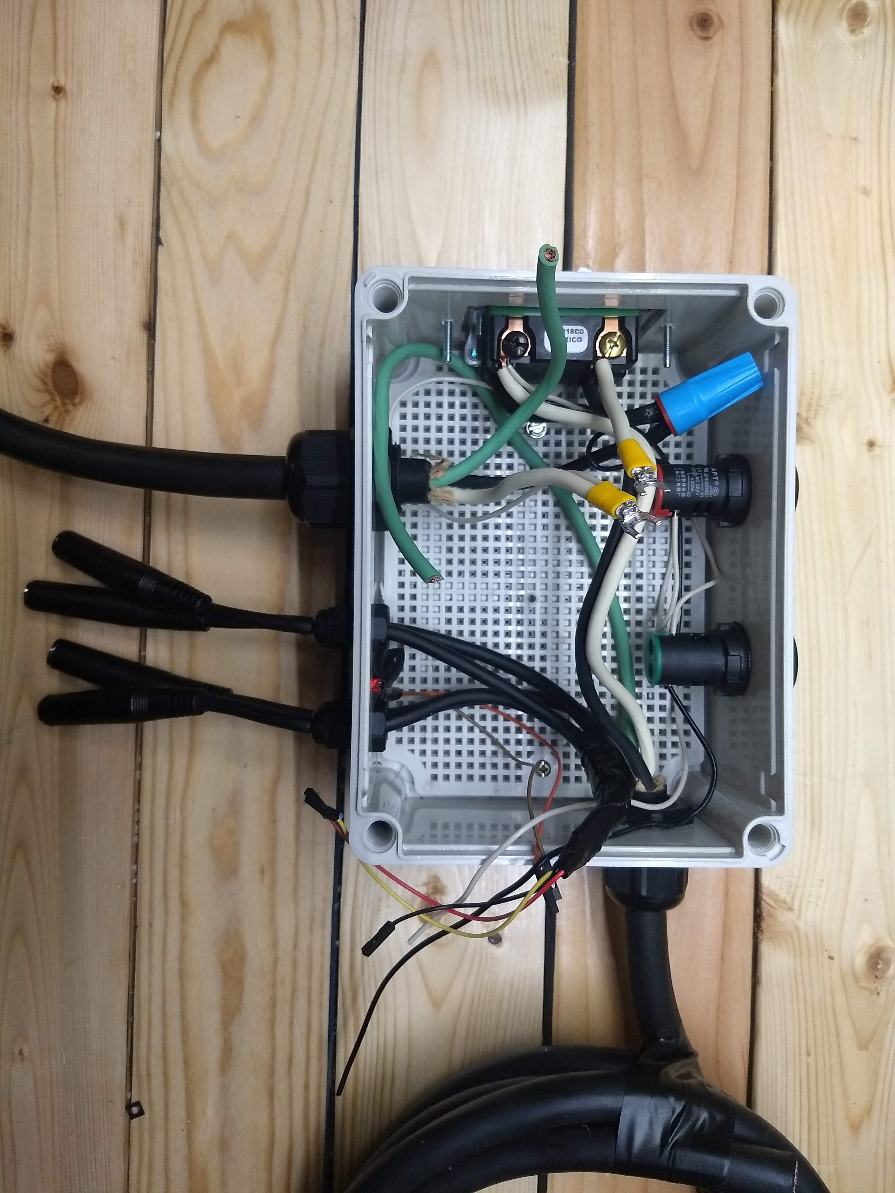
It's coming along nicely, I've got the box all buttoned up and I'm convinced that it'll be just fine! I even made a cool mount for my raspberry pi to keep it upright inside the box. Time will tell if it gets too hot in there with the SSR and heatsink, if it does I'll just move the heat sink outside the box.

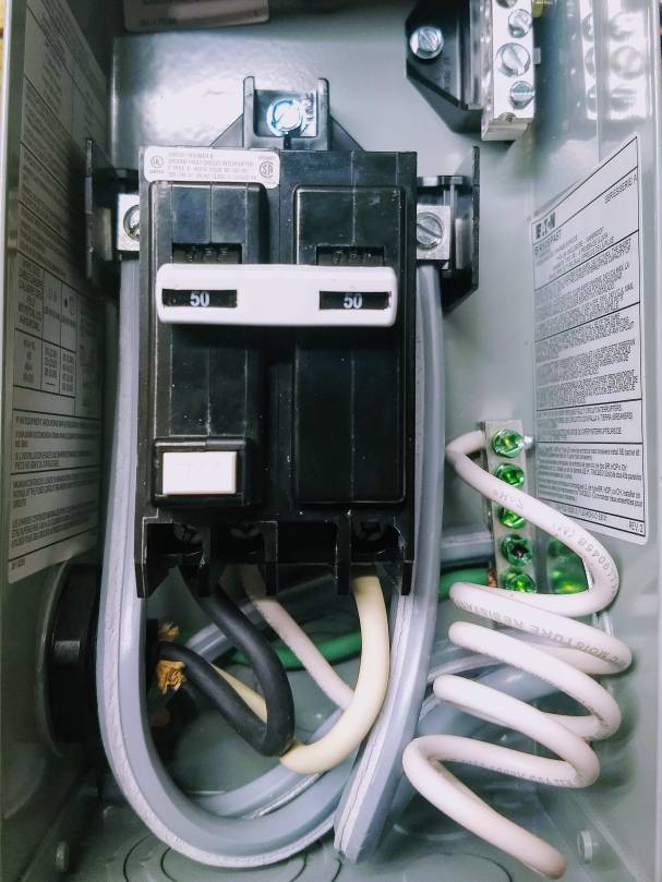
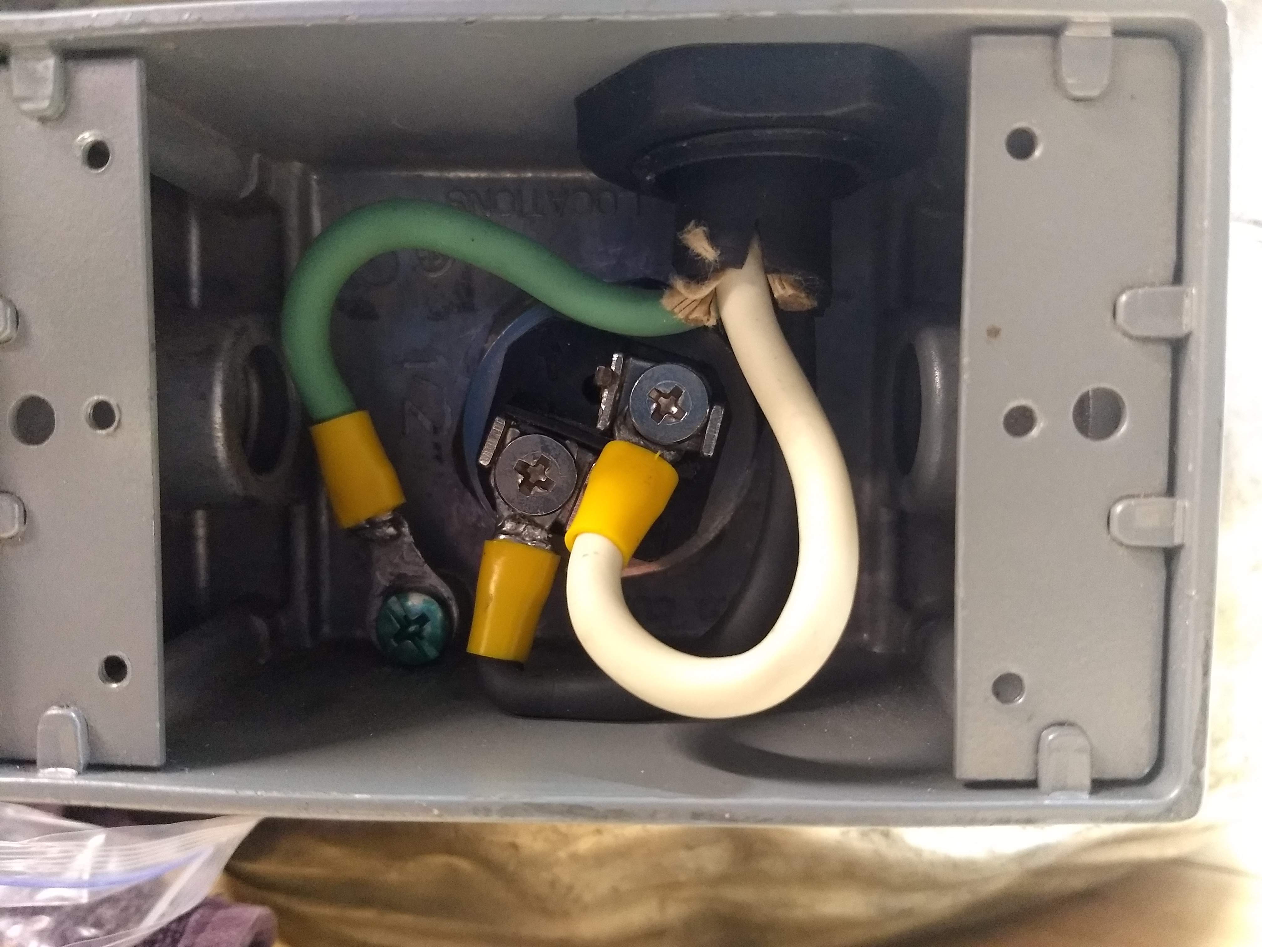
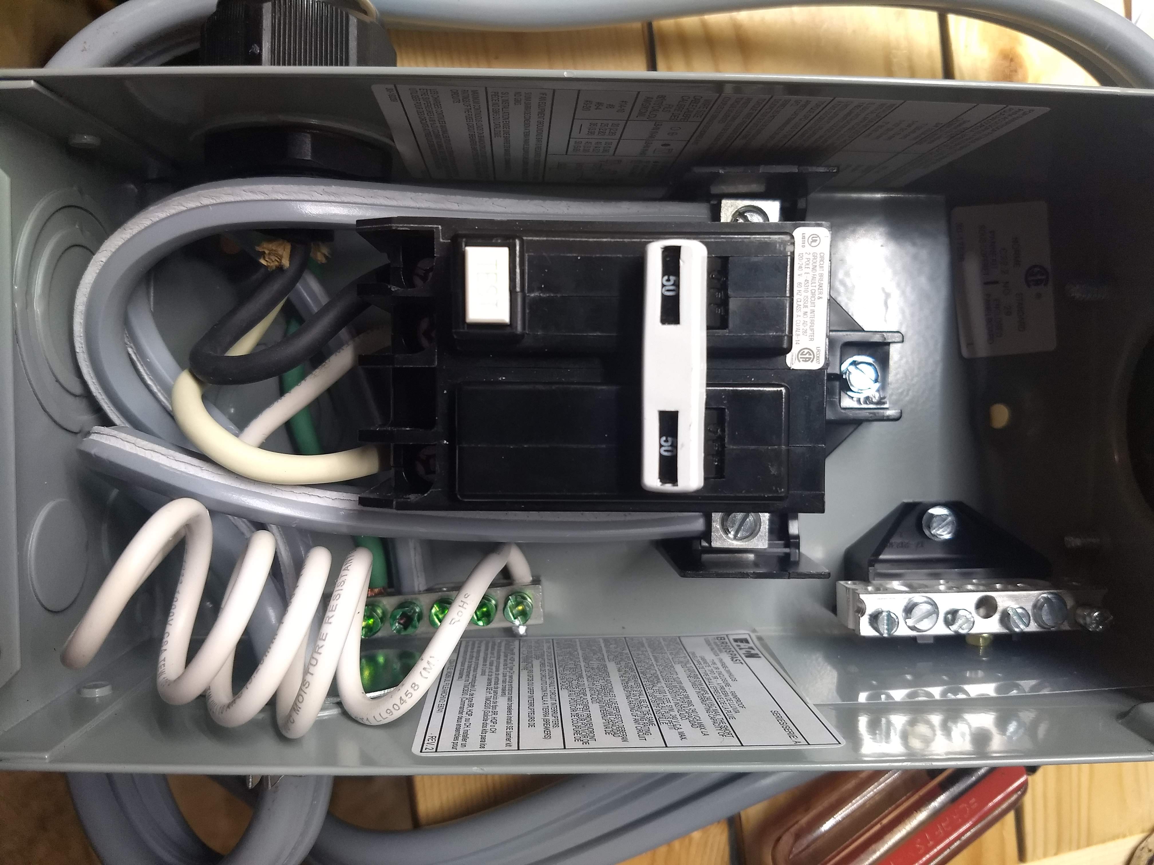
For what I think is going to be my final question, the wires in the wall are black, white and bare (connected to a 30 amp double pole breaker in the main panel). I plan on wiring these to a dryer outlet with three prongs, adding a dryer cord to the spa panel and then wiring the control panel directly to the spa panel. The directions for the dryer cord outlet say that it should have a red wire a black wire and a white wire. Is there any concern attaching it with my method?

As always you guys are unbelievable for taking the time to answer questions and bring me from zero knowledge to at least something!
Black, white and bare would be hot, hot, ground. A neutral wire needs to be insulated to meet code, since a neutral is intended to be a current carrying conductor in normal operation, but a ground conductor should carry current only in a fault situation. You can use a neutral as ground in a 240V system, as long as you don't have any 120V requirements, in which case you need a neutral and a ground.

As long as you meet the no 120V requirement, you can use a three wire dryer plug. Color matching the hots is irrelevant, but the green and bare need to be paired.

Brew on :mug:
That's great news and in line with what I was thinking. There isn't any 120 in the control box.

My trouble is figuring out how to wire the spa panel to the 3 wire and still have GFCI protection. Searching HBT and the web just leads to a "yes,no maybe so" confusion?
 
That's great news and in line with what I was thinking. There isn't any 120 in the control box.

My trouble is figuring out how to wire the spa panel to the 3 wire and still have GFCI protection. Searching HBT and the web just leads to a "yes,no maybe so" confusion?
Wire as shown in the attachment to this post. You might find some of the post following that post informative.

Brew on :mug:
 
At the risk of causing confusion.......

That's great news and in line with what I was thinking. There isn't any 120 in the control box.

My trouble is figuring out how to wire the spa panel to the 3 wire and still have GFCI protection. Searching HBT and the web just leads to a "yes,no maybe so" confusion?
In a different thread when I asked a similar question for the heat element - a user named "itsnotrequired" posted this:
many gfci breakers need that neutral connection for the test button to function properly. the gfci will still function properly without the neutral, it is just the test button won't work. the problem is when there is NOT a neutral coming into the spa panel and folks start jumpering neutral to ground...

And this confirms the post that doug293cz mentions above.

So it appears that you really don't have to worry about it. Just DON'T connect your neutral and ground together in any sub-panel. The only place they can be tied are in the main panel in the house (or wherever the power from the electric company arrives).
 
Sounds good - I like the idea of testing it with a resistor.
It looks like it should trip if I connect a 47KΩ between the ground screw and the load side of the Levitron switch in the box ?

Will turning the switch on immediately trip the GFI ?
 
Sounds good - I like the idea of testing it with a resistor.
It looks like it should trip if I connect a 47KΩ between the ground screw and the load side of the Levitron switch in the box ?

Will turning the switch on immediately trip the GFI ?
Yes the whole idea is that it trips fast enough to save your life when any current leaks.
 
Back
Top