BruControl: Brewery control & automation software

Homebrew Talk - Beer, Wine, Mead, & Cider Brewing Discussion Forum

Help Support Homebrew Talk - Beer, Wine, Mead, & Cider Brewing Discussion Forum:

This site may earn a commission from merchant affiliate links, including eBay, Amazon, and others.
We posted firmware beta version 46. This version includes some fixes and paves the way for some advanced functionality in the future. It also uses a better memory management system for its real-time algorithms. This will help with memory-limited interfaces like the MEGA.

New Interface Wiring Maps for v46 are posted as well. That said, hold off on trying it until we publish new Interface Definition files (.brumc) for BruControl. Going forward, we will NOT use ports 100+ for Analog Inputs. These inputs will use their native numbers from here on (eg. MEGA pin A0 which maps to BC port 100 will be port 54, etc.). This will require everyone to switch Analog Inputs to these new ports - sorry!
Not always as simple as deleting a Device Element and making it correspond to your new mapping if I use my scheme. I have so many Elements that I name them in a very specific way.

For example my Port 105 on my Brewery Mega is:
MB_105_10KLittleMac_B1


The name is unique and tells me a lot about what it is. I decided to do this when I was finding that repeating something on another workspace generated an error. So long ago I do not remember why, but by doing this and using the Alias Display Name, the issue was resolved.

I would suggest that you allow both the "old" analog Numbers AND the new native ports going forward if possible in your Interface Definition files (.brumc). That would allow anyone that has already assigned the "old" port numbers to do nothing and new Analog inputs could use your new scheme.
Any one that has the "old" Analog numbers could upgrade to the new firmware and at their own pace and eventually meet the new scheme. You could give a year to get to the new scheme.

Sorry, this just isn't possible. Once we set the port numbers in the firmware, they are fixed and expect those to be used by BruControl.

That said, you can edit your configuration file (or we can) to change the port numbers without deleting and recreating the Analog Input Elements.
 
We posted firmware beta version 46. This version includes some fixes and paves the way for some advanced functionality in the future. It also uses a better memory management system for its real-time algorithms. This will help with memory-limited interfaces like the MEGA.

New Interface Wiring Maps for v46 are posted as well. That said, hold off on trying it until we publish new Interface Definition files (.brumc) for BruControl. Going forward, we will NOT use ports 100+ for Analog Inputs. These inputs will use their native numbers from here on (eg. MEGA pin A0 which maps to BC port 100 will be port 54, etc.). This will require everyone to switch Analog Inputs to these new ports - sorry!
Looking forward to what comes after. :) Thank you for all the updates.
 
Rather than
"That said, hold off on trying it until we publish new Interface Definition files (.brumc) for BruControl. Going forward, we will NOT use ports 100+ for Analog Inputs. These inputs will use their native numbers from here on (eg. MEGA pin A0 which maps to BC port 100 will be port 54, etc.). This will require everyone to switch Analog Inputs to these new ports - sorry!"

Why not have both the Old Ports and the new ones active for one year. That would give everyone a change to upgrade to the firmware and some time to change their configuration within the year time frame.
 
Your line 7 error is because you are looking for "state" but that is not a valid DI operator. Try "value" instead.
If you look at my post I did try both state and value. They both produced the same error.

if "MB_43_di_Blue_DINS" value = = true
throws this error:
[ERROR Line 7: 'true' is not a valid second operator]

or

if "MB_43_di_Blue_DINS" state = = true
throws this error:
[ERROR Line 7: 'true' is not a valid second operator]

Have you used Digital Inputs? Post some code and that may help.
 
Have you used Digital Inputs? Post some code and that may help.
Of course,

1658270598858.png
 
Rather than
"That said, hold off on trying it until we publish new Interface Definition files (.brumc) for BruControl. Going forward, we will NOT use ports 100+ for Analog Inputs. These inputs will use their native numbers from here on (eg. MEGA pin A0 which maps to BC port 100 will be port 54, etc.). This will require everyone to switch Analog Inputs to these new ports - sorry!"

Why not have both the Old Ports and the new ones active for one year. That would give everyone a change to upgrade to the firmware and some time to change their configuration within the year time frame.

You can use your existing FW and definition files - no problem. But we can't have two new versions of FW. Between the different interfaces, different connection types, it's too much to manage. Also the new FW and definition files will give you access to the DO's freed up by @staffordj 's recommendation. Something about an egg and an omlette... also I have never liked the '100' ports for Analog Inputs... so much better to use their native assignments.

If you have a concern with switching, you can send us your config file and we'll move it over for you. Switching then will be totally transparent and easy for you.
 
it was as @BrunDog said "==" and not "= =" with the space. It threw a different error with state this time :
[ERROR Line 7: No property found with name 'state']

It was not clear to me in the manual weather it should be "state" or "value". I am always confused as to which is correct and the manual sums my confusion up:

"The state is presented as the Element’s value and will either be ON or OFF ..."

"value" throws no error.
 
I could see how that can be confusing. That statement is made with respect to the overview of the Element, not the scripting language. But we'll edit that to remove the overlap.

The best resource for scritping is the Element Properties section. You can see there that Digital Inputs can only have properties ActiveLow or Value (along with the properties common to all Elements and Device Elements). There is no State there, therefore it cannot be used in a script as a property of a Digital Input.
I see that now. It would be nice if you could also list the scripting properties for each element with it properties in it description in the User Manual.

I know that writing Users Manuals is a chore and pain (and normally an afterthought). Having all the information with its Main Entry is what I found best when I was doing it. I would suggest that you keep the Scripting Section but add the following after each Device Element:

Device Input Scripting:

All Elements
Visibility (Enumerated Read/Write: default/visible/hidden/hiddenlocked)
DisplayName (Read/Write: string)
DisplayText (Read Only: string)
Background (Enumerated Read/Write: 1/2/3)
ID (Read Only: string)
Element ID (Read Only: string)
Port ID (Read Only: string)
All Device Elements
Enabled (Enumerated Read/Write: true/false)
Connected (Read Only: true/false)
RefreshMultiple (Read/Write: number)
Digital Input
ActiveLow (Read/Write: true/false)
Value (Read/Write: true/false)

Example:
A Float that is wired as a Digital Input and a Valve that will shut when Float is "made".

// Brewery Float is wired as a Digital Input
// Fill Valve is a 24 vdc ball valve
[LoopBF]
if "Brewery Float" value == True
"Fill Valve" state = False
endif
goto LoopBF

or

// Brewery Float is wired as a Digital Input
// Fill Valve is a 24 vdc ball valve

wait "Brewery Float" value == True
"Fill Valve" state = False

While this is something of a repeat within the manual, since the manual is digital it would be easy to cut and paste and add the extra. When it is with the Main Section as well, your end user may better see it rather than trying to find it elsewhere.

That being said, I think having all the scripting stuff together is good as well and the above only a repeat.


BTW, the value of a Digital Input is read/write which is fine because you can control the flow (like overriding a Float with a button) with scripting as well as the Physical Element Interface:

In your manual. Somewhat True except you can control via scripting:

Digital Inputs have no User Control, as they are read-only Elements
 
If someone is interested i bought couple of those lately and they work good.
Nice form factor with din mount.
https://robotdyn.com/catalog/smarth...ol-programmable-esp32-4-relays-controller-boa
For extra in/outs you need to desolder 4 micro switches and use a USB dongle to programm IT.
Just a heads up for everyone that the Robotdyn site seems defunct. No confirmation email, and the emails lead to dead ends. My bank statement shows the card info was manually entered rather than charged normally when entered on a site. Searches for them don't show promising results on being legit (at least anymore). Might have to look for this product in other places.
 
We have bought products from them in the past, namely a MEGA with integrated Ethernet.

Hope they are still legit!
Their products are sold sparingly now at other places, and the Google results for aliexpress and banggood lead to dead links.. I'd like to hope it's still good, but dead-end emails to sales and then support don't give me a good feeling.. and no confirmation email isn't ideal either.. I'm hoping to find this at least sold elsewhere. May be stuck with the (otherwise great) Lilygo relay board and a 5v step down.
 
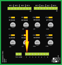
I know you should have your TF-4 close to the Mega Interface. Because of all the probes wiring, it would be better for me to place it about 24" away from the Interface. I could place it closer if needed (maybe right below the interface), but would be less spaghetti if the 24 inches or less. Any comments?
 
And along those lines, it would be far easier for me to change the ports numbers now for the Eight Elements I have as I have not used them in my scripting yet. I do have them as inputs on some of the Elements but that is fairly easy to change. What is timeline for the native ports #'s instead of the 100s for the Analog inputs?

BTW, I use the port number as Part of my Element name and would prefer it is correct so I do not get confused later.
 
I know you should have your TF-4 close to the Mega Interface. Because of all the probes wiring, it would be better for me to place it about 24" away from the Interface. I could place it closer if needed (maybe right below the interface), but would be less spaghetti if the 24 inches or less. Any comments?

Distance is less important than shielding and separation from other noisy wires in this case.
 
What would be considered noisy wires?

I have:
Heating Elements (240 vac) Control 0-10 vdc via Mega Unishield P Pin and AA-2)
Rip Tide Pumps (110 vac) (Control 12 vdc via Mega Unishield D Pin: Pump Control separated in separate box
Electric Valves (24 vdc-Via Grand Central Unishield D Pins)
LEDs (12 vdc)
Solenoid Gas Valves (12 vdc via Mega Unishield)
ElectoMechanical Contactors (Control 12 vdc via Mega Unishield D Pins: Contactors separated in separate box)

I have no compressors sharing any of the circuits except at the Electric Circuit Breaker panel.


The closest wires would be the Electric Valves wiring as planned but can separate if an issue.

I do have a Glycol Chiller and Kegerator in the next room.
 
That's sorta what I thought. I know compressors are EMI issues but I thought DC voltage not too much for EMI. All of the AC is in metal conduits and somewhat away from all the Valve and Temp probe wiring,
 
Are we still waiting on anything to use Firmware v46? If so, timing? I want to write some scripting and I use the Port/PIN on my Temperature Probe Names ( My MB100_10K_MashReturn_B1 will become MB54_10K_MashReturn_B1) I would rather have the new scheme before I add anything in my scripts.
We posted firmware beta version 46. This version includes some fixes and paves the way for some advanced functionality in the future. It also uses a better memory management system for its real-time algorithms. This will help with memory-limited interfaces like the MEGA.

New Interface Wiring Maps for v46 are posted as well. That said, hold off on trying it until we publish new Interface Definition files (.brumc) for BruControl. Going forward, we will NOT use ports 100+ for Analog Inputs. These inputs will use their native numbers from here on (eg. MEGA pin A0 which maps to BC port 100 will be port 54, etc.). This will require everyone to switch Analog Inputs to these new ports - sorry!
 
Also, I dropped a Screw down on my TF-4. Are they 2.54 mm screw terminals?


I found it!!!! but would still like if all the Specs were available for all of your boards.

i.e.
Terminal Size
AWG
L x W x H
Voltage
Operating Temps
 

Attachments

  • TF4 arrow.png
    TF4 arrow.png
    32 KB · Views: 0
Last edited:
Has anyone tried using this ESP32 + relay board from Lilygo (and with success)? Amazon.com: LILYGO TTGO T-Relay ESP32 Wireless Module DC 5V 4 Groups Relay Development Board 4MB Flash WiFi BLE Remote Switch Control (T-Relay T- U2T Kit) : Electronics

It's incredibly ideal for a BC setup, but it comes with its own USB to TTL programmer that must be used to interact with the ESP32, which is causing me issues when trying to setup WiFi. I can load the BC firmware, seemingly, but when it comes to setup, I can't get Termite to play nice. If I boot the ESP32 regularly, I get the attached image, seemingly showing AP mode (and I see the WiFi signal, not sure what I can do with that, and I have no password). I try entering "%0&15;" (no quotes), but nothing happens.

Test 1: When I press Boot and the U2T button, the ESP32 goes into download mode, but then there's nothing on Termite other than [00][00]. "0&15;" doesn't work either.

In some random chain of events, I did manage to het "0%15;" to trigger, and I entered the WiFi details, but when I rebooted the device, it never appeared on my WiFi.

Test 2: I tried installing BruControl.45O.ESP33.W.bin, then tried 45L to make sure it wasn't a version issue with this board (which I doubted). No difference.

Test 3: BruControl.OutputsTest.ESP32.S.bin works though, so that's a great sign. The four relays light up (two blink), then LED5 blinks, then the cycle repeats consistently.

Test 4: I also connected the board to a 12V source on the input pins incase it was a powering issue. Still nothing appeared.


The chip is ESP32-WROVER-B, if that offers any insight.

Any thoughts here, BC community?
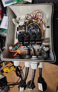
I got the LILYGO TTGO Relay going in its first box, and all is working well so far. I ran wire to each relay's COM line underneath to cut down on wires running from port to port, and that works well.

Edit: I also used the unusable relay's NC line to power my stepdowns. So not all is wasted with the unusable relay :)

I'm having issues with my pressure tranducer climbing from 0 to 30, back down, then back up, so I need to go and check the voltage divider resistors and wiring in general. It's connected to its own 5v stepdown up top (the board is powered by a 12v stepdown up top as well). I don't think noise would make it keep going up and down (noise should just have it jump a bit, I believe, but I'm not an electrical engineer... just a googler). Any insight is welcomed here.

I also found that I can't use a LCD screen since the SDA port isn't available (it's the unusable relay...maybe I can rework that connection), so that idea is scratched for now. I may consider a separate ESP32 or 8266 to run an LCD with updated data.

All in all, very useful board if your setup only needs three relays.

Update 1: the transducers have acted up sometimes on my old setup, and now they are bad at any spot. May be time to replace them.
 

Attachments

  • 20220727_231342.jpg
    20220727_231342.jpg
    1.9 MB · Views: 0
Last edited:
Just a heads up for everyone that the Robotdyn site seems defunct. No confirmation email, and the emails lead to dead ends. My bank statement shows the card info was manually entered rather than charged normally when entered on a site. Searches for them don't show promising results on being legit (at least anymore). Might have to look for this product in other places.
So there may be hope here. I just got a USPS notification that a package was received from Cainiao, a logistics arm of the Alibaba Group. I have no other orders expected from China, nor any orders that aren't being tracked already. Not sure why the Robotdyn site offers no order updates and the emails lead to dead ends, but maybe there's hope of getting this controller + relay board.....after I just finished my first LILYGO setup, hah.

But if this in fact comes in, I'll update the group. I'll gladly swap out my LILYGO for a board that needs one power lead in and gives me some ports back.
 
Are we still waiting on anything to use Firmware v46? If so, timing? I want to write some scripting and I use the Port/PIN on my Temperature Probe Names ( My MB100_10K_MashReturn_B1 will become MB54_10K_MashReturn_B1) I would rather have the new scheme before I add anything in my scripts.
Bump
 
Question... for micros which have DAC's (Digital-to-Analog) converters, should we simply replace those GPIO's PWM Output into Analog Output automatically, or create a new Element which would allow you to keep the pin as PWM or Analog Output?
 
OK, new application has been uploaded to accommodate FW v46+. These include the new definition files for that firmware to include the expanded pin/port combinations for MEGA and Grand Central (analog input pins can be digital output, etc.). In making this change, we eliminated the port 100+ numbering for Analog Input pins, and have implemented their native port numbers, which are now shown in the Interface Wiring Maps for FW 46+.

Firmware v46 is currently 46B on the website, as 46A had a problem with the counter rate calculation. Per notes above, v46 is a re-write of the internal database and aims to save memory and aid in expansion in the future. As such, it is definitely in beta status. If you use it, please let us know any issues ASAP and we'll fix them.

Firmware v45Q uses the prior database system but does add the new pin/port combinations, so if you wish to move to those, you can do it without using a beta FW.

We added new Wiring Maps in the definition files so you can select which one you wish you use. There will be the prior versions (Default for serial and Ethernet and Wi-Fi for Wi-Fi) plus these names with a _FW_v46 suffix. If you select a new wiring map, your old Device Elements associated with that interface will be deleted. As a work-around, you can manually edit your selected Wiring Map inside your configuration file. To do this:

1. Close the BruControl application if it is running. Open the BruControl folder inside your Documents folder.
2. Make a backup copy of your configuration file (for example, default.brucfg). Don't skip this step - if you corrupt your configuration file, you will have a backup (in addition to those likely in the Config Backup folder). BTW, its always a good policy to make your own backups, and save them off your computer should it have a catastrophic crash.
3. Open the existing configuration file (which is in XML format) and search between the <Device> and </Device> tags which should be at the top of the file. For the interface you are looking to move over (listed by the <Name> tag), find the <WiringMap> tag at the bottom of the list and edit it to reflect what you are looking for. For serial connections, if it was 'Serial', change it to 'FW_v46'. For network connections, if it was Ethernet, change 'Default' to 'Ethernet_FW_v46', or if it was Wi-Fi, then change 'Wi-Fi' to 'Wi-Fi_FW_v46'.
4. Save the file and restart BruControl. You will need to manually delete and replace any Analog Inputs which used the old port numbers as they will not work any longer.

LMK if you have any questions or concerns!

Edit: Also, all v46 FW will now use 12-bit Analog-Digital conversions if the interface supports it (ESP-32 and Grand Central). So make sure you edit any calibrations to handle the range difference.
 
Last edited:
I got the LILYGO TTGO Relay going in its first box, and all is working well so far. I ran wire to each relay's COM line underneath to cut down on wires running from port to port, and that works well.

Edit: I also used the unusable relay's NC line to power my stepdowns. So not all is wasted with the unusable relay :)

I'm having issues with my pressure tranducer climbing from 0 to 30, back down, then back up, so I need to go and check the voltage divider resistors and wiring in general. It's connected to its own 5v stepdown up top (the board is powered by a 12v stepdown up top as well). I don't think noise would make it keep going up and down (noise should just have it jump a bit, I believe, but I'm not an electrical engineer... just a googler). Any insight is welcomed here.

I also found that I can't use a LCD screen since the SDA port isn't available (it's the unusable relay...maybe I can rework that connection), so that idea is scratched for now. I may consider a separate ESP32 or 8266 to run an LCD with updated data.

All in all, very useful board if your setup only needs three relays.
Been away for a while, thanks for testing this board, I have been wanting an off-the shelf unit for my shop's garage door 3-button operator, and it needs 2 NO relays for up and down, and one NC relay for 'stop'
 
Been away for a while, thanks for testing this board, I have been wanting an off-the shelf unit for my shop's garage door 3-button operator, and it needs 2 NO relays for up and down, and one NC relay for 'stop'
This sounds ideal then for something like that then. This has its limitations with BC due to not having its own 5V pin, one relay being GPIO21, and it taking 3 minutes in setup mode since GPIO5 is a relay and getting pulled low at bootup. But its form factor is great, and it does work well so far.
 
So there may be hope here. I just got a USPS notification that a package was received from Cainiao, a logistics arm of the Alibaba Group. I have no other orders expected from China, nor any orders that aren't being tracked already. Not sure why the Robotdyn site offers no order updates and the emails lead to dead ends, but maybe there's hope of getting this controller + relay board.....after I just finished my first LILYGO setup, hah.

But if this in fact comes in, I'll update the group. I'll gladly swap out my LILYGO for a board that needs one power lead in and gives me some ports back.
Never got any confirmation of order but it arrived yesterday.
 
Edit: Also, all v46 FW will now use 12-bit Analog-Digital conversions if the interface supports it (ESP-32 and Grand Central). So make sure you edit any calibrations to handle the range difference.
V45 already supports 12 bit on the GC. This tripped me up when I was calibrating on v45, I was expecting 10 bit based on the documentation but it is 12 bit.
 
Never got any confirmation of order but it arrived yesterday.
Nice! What I assume is mine is out for delivery right now. I guess I can forgive lack of communication and just know that if I order another, it'll show up magically, eventually, hah. Maybe I'll just order from AliExpress for a bit of reassurance.
 
OK, new application has been uploaded to accommodate FW v46+. These include the new definition files for that firmware to include the expanded pin/port combinations for MEGA and Grand Central (analog input pins can be d.....

Four Questions:

1> In looking at my configuration, my ESP32 is set up as Network TCP. It is Wi-Fi~ed to the router and seems to work fine. In my configuration file the <WiringMap> tag is

<WiringMap>Default</WiringMap>

Assuming it should be changed to

<WiringMap>Ethernet_FW_v46</WiringMap>

2> I have four interfaces. I assume that any Interface that you want to be v46 and on, the <WiringMap> tag needs to be changed for each one in the brucfg file.?

3> Can you have a mix between v45 and v46 interfaces within the same brucfg file?

4> What if you add a new interface?
 
V45 already supports 12 bit on the GC. This tripped me up when I was calibrating on v45, I was expecting 10 bit based on the documentation but it is 12 bit.
Yes, correct. Thanks for that reminder. It’s only “new” on the ESP32.

That said, if anyone has any trouble moving from one Wiring Map to the new ones, feel free to send us your configuration file and we can swap it over for you. I know it’s a pain… but a growing pain. Eggs —> omlette… you know the deal.
 
Back
Top