BruControl: Brewery control & automation software

Homebrew Talk - Beer, Wine, Mead, & Cider Brewing Discussion Forum

Help Support Homebrew Talk - Beer, Wine, Mead, & Cider Brewing Discussion Forum:

This site may earn a commission from merchant affiliate links, including eBay, Amazon, and others.
Here it is. No three way buy lots of 2 way valves. We can do two 25 gallon batches at the same time and even clean one Brew Kettle while the other is still in use.
Ah yes. Makes sense now that i see each vessel has its own pump so that it is always at the start of the loop it is using. Can also see that you are segmenting two different parts of the loop in order to be able to use two different pumps at the same time. Picture worth a thousand words Very clever. Is that a pro brewer standard or did you work that out on your lonesome?
You may get a stuck mash if the recirc flow is too high. My last batch I upped my flow from 1 gpm to 2gpm. The flow steadily reduced from 2 to 1.5 over 30mins as the bed compacted. This will depend on a lot of things like your grind, mash composition, vessel and screen, but not having control could lead to issues.
Thx @staffordj I am going to leave my Proportional valve at the pump 2 outflow and then also have regular ones after that in serial for the two directions: mash tun re-circ and chiller. That will allow me to use the Proportional for both re-circ and chilling.

I have a manual 3 way that I can stick on the chiller out for now. one way to whirlpool, other way to fermenter. Will need to replace manual 3-way with a tee and two new motos at the chiller output so I can avoid the horror of touching a ball valve. :) I think that will officially max me out on uniflex v2 binary outputs (11)

Cheers for the help.
 
You may get a stuck mash if the recirc flow is too high. My last batch I upped my flow from 1 gpm to 2gpm. The flow steadily reduced from 2 to 1.5 over 30mins as the bed compacted. This will depend on a lot of things like your grind, mash composition, vessel and screen, but not having control could lead to issues.
Rice Hulls! They are magic.
 
"Ah yes. Makes sense now that ... did you work that out on your lonesome?

On my own. I had a disaster on April 16, 2020 as my barn burned down (unrelated to brewing). I got to start over and had been brewing since 2008. We had gone to a hard piped manifold and 5 pumps before. We generally NEVER touch a hose with a couple of exceptions (the hose to the fermenter is sanitized in a recycle).

Years ago I removed a hose and got some very hot Wort on my foot. I ended up at the emergency room about midnight when I went to bed. When I took off my sock, I had some significant blisters. It did not hurt which is a clue. It was only very bad 2nd degree burns. We bought more pumps the next day and hard piped the brewery, No more hose moving.

We clean while we are brewing and cycle PBW in the pumps and vessels. The loop is for that purpose. In addition, we use a modified HERMS where we use a counter flow chiller to maintain the Mash Temp. Works like a charm. Since we use distilled water in some of our Lagers, we also use the small Radiator (15 gal) to heat the distilled water for Strike.
 
Is there anyway to do a Universal clean
clear.png
(all the scripts at once) of the Output and Variable panes of the Script Window.

I would like to clean them all prior to running a brew session.

Would really be nice to have a script command to clean both the output and variables of a script.

some thing like:

cleanoutput "my script"
cleanvariable "my script"

I could then add these to my start up routine. That would take care of universal clean as well.
 
Really for troubleshooting (debugging) issues in my scripts. I did something and my scripts get in an endless loop.

On script is causing another script to go backwards and not complete what it is doing. I was cleaning up all my print commands in the scripts when I messed it up. I obviously deleted something, I use the print command to see if a script executes to a point. The is no error thrown as the computer commands are good, just trying to see why it is doing what it is doing. Just be easier to clear the output pane automatically .


In practice, I only look at the output script when writing a new script or section of a script.
 
For anyone needing port 0 on their ESP32 / ESP8266, or Feathers, we updated the FW to accommodate it. Grand Central is *possible*.

We avoided certain ports like these because serial communications are used there, but since we don't need it during network communications, it is possible to use those. We'd like to test the FW further, but if you are in dire need of that port, LMK! The version will be 45P and will be updated shortly. I don't recommend you upgrade if you don't need it.
 
On arduinos, analog ports can be used as digital pins also. With the Brucontrol interface as I understand it, they can only be analog inputs. On the mega or grand central this would add 15 potential digital io pins if you don't need the analogs.
 
Well, I just looked and you may damn be right... The MEGA 2560 Analog Input pins seem to be able to become digital output pins, too. We'll do some testing on it!

Edit: And ya'll gonna really hate if we then convert port 100-115 into 54-69! o_O
 
Last edited:
Been out of the loop for a while, has there been any thought on integrating in an off-the-shelf wireless thermometer system of some sort, such as a bbq or smoker thermometer? I got a new pizza oven and want to monitor/alert temps, and maybe someday control them...
View attachment 769191
Very late and appears to be off-topic, but replying to @clearwaterbrewer question in May:
I built a HeaterMeter years ago for controlling temps on my Costco version of the Big Green Egg

HeaterMeter Hardware v4.3.3, v4.3.4, v4.3.5, v4.3.6

and

HeaterMeter 4.3 Hardware · CapnBry/HeaterMeter Wiki
 
Reading the UM-1 Notes, for heat, it seems best to power a Unishield with just 5v, The internal regulator on a Grand Central will convert that to 3.3 v and the heat is not an issue according to the notes. My interface is inside a barn and it is not A/Ced so I want the less heat generated possible.

All of my transformers, Proportional Controllers, SSRs and Electrical Contractors are in separate boxes.
The only things in the Interface box are the 3 Interfaces, an AA-2, and a TF-4.

I have a 12 vdc 5 amp transformer to power my interfaces. It will power the Grand Central Unishield, A Mega 2560 Unishield and an EtherMega.

I have set the output exactly at 5 v with the little Unishield "VR ADJ" potentiometer.


Is my plan valid?

The Ether Mega is so I can create pseudo Elements (real elements but wired to nothing). I use these to put the same Element on different workspaces. For example, I have the real "Yellow Pump" on my Mega Unishield on my main brewery workspace, and I have a pseudo "Yellow" pump on my Second Batch workspace. I can control the real "Yellow Pump" (via scripting) from either workspace.

I know I can do that with other methods but the interface is not much and all the Elements have the exact same "feel" and properties so they can be an exact match except for their native name.

My Power banks on the Unishields have their own transformers (one for the Grand Central and one for the Mega) as well as a 5 vdc Buck for anything needing 5 volts. Most of the output of the Power banks is for 12 vdc Contactors (there are 8 total). Everything else is minimal or proportional (and off the P Pin).

The 5 vdc Buck is 20 amps so I could also use that to power the interfaces if that would be better. If the 5 vdc buck is a better option, let me know.
 
Last edited:
I'm not sure what you are saying... are you feeding the UniShield with 5V, or setting the VR output to 5V? Our default, and what we suggest, and what I think you are saying, is you feed the US with 12 or 24VDC (likely the same power driving your other DC devices), and keep the VR output to 5V, with the switch VR-->5V. This will power the GC or MEGA interface microcontroller board with 5V, which keeps them very happy. The MEGA will run on that 5V directly and the GC will use its onboard regulator to drop that to 3.3V.
 
Very late and appears to be off-topic, but replying to @clearwaterbrewer question in May:
I built a HeaterMeter years ago for controlling temps on my Costco version of the Big Green Egg

HeaterMeter Hardware v4.3.3, v4.3.4, v4.3.5, v4.3.6

and

HeaterMeter 4.3 Hardware · CapnBry/HeaterMeter Wiki

Nice! Lots of ways to do it. BC can definitely read temps and control a fan. Been meaning to build a quickie, just time burn and I have been lazy on my smoking lately as my BGE tends to hold temp pretty well based on the vent positions.

Unfortunately 1-wire caps out at 255 deg F so these aren't usable. Need to be RTD or thermistor, which needs the extra hardware to integrate. Driving a fan is super easy via a FET or DC:DC SSR, or even standard electromechanical relay.
 
Has anyone tried using this ESP32 + relay board from Lilygo (and with success)? Amazon.com: LILYGO TTGO T-Relay ESP32 Wireless Module DC 5V 4 Groups Relay Development Board 4MB Flash WiFi BLE Remote Switch Control (T-Relay T- U2T Kit) : Electronics

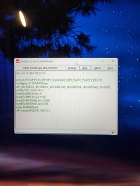
It's incredibly ideal for a BC setup, but it comes with its own USB to TTL programmer that must be used to interact with the ESP32, which is causing me issues when trying to setup WiFi. I can load the BC firmware, seemingly, but when it comes to setup, I can't get Termite to play nice. If I boot the ESP32 regularly, I get the attached image, seemingly showing AP mode (and I see the WiFi signal, not sure what I can do with that, and I have no password). I try entering "%0&15;" (no quotes), but nothing happens.

Test 1: When I press Boot and the U2T button, the ESP32 goes into download mode, but then there's nothing on Termite other than [00][00]. "0&15;" doesn't work either.

In some random chain of events, I did manage to het "0%15;" to trigger, and I entered the WiFi details, but when I rebooted the device, it never appeared on my WiFi.

Test 2: I tried installing BruControl.45O.ESP33.W.bin, then tried 45L to make sure it wasn't a version issue with this board (which I doubted). No difference.

Test 3: BruControl.OutputsTest.ESP32.S.bin works though, so that's a great sign. The four relays light up (two blink), then LED5 blinks, then the cycle repeats consistently.

Test 4: I also connected the board to a 12V source on the input pins incase it was a powering issue. Still nothing appeared.


The chip is ESP32-WROVER-B, if that offers any insight.

Any thoughts here, BC community?
 

Attachments

  • 20220716_140043.jpg
    20220716_140043.jpg
    1.2 MB · Views: 0
Has anyone tried using this ESP32 + relay board from Lilygo (and with success)? Amazon.com: LILYGO TTGO T-Relay ESP32 Wireless Module DC 5V 4 Groups Relay Development Board 4MB Flash WiFi BLE Remote Switch Control (T-Relay T- U2T Kit) : Electronics

It's incredibly ideal for a BC setup, but it comes with its own USB to TTL programmer that must be used to interact with the ESP32, which is causing me issues when trying to setup WiFi. I can load the BC firmware, seemingly, but when it comes to setup, I can't get Termite to play nice. If I boot the ESP32 regularly, I get the attached image, seemingly showing AP mode (and I see the WiFi signal, not sure what I can do with that, and I have no password). I try entering "%0&15;" (no quotes), but nothing happens.

Test 1: When I press Boot and the U2T button, the ESP32 goes into download mode, but then there's nothing on Termite other than [00][00]. "0&15;" doesn't work either.

In some random chain of events, I did manage to het "0%15;" to trigger, and I entered the WiFi details, but when I rebooted the device, it never appeared on my WiFi.

Test 2: I tried installing BruControl.45O.ESP33.W.bin, then tried 45L to make sure it wasn't a version issue with this board (which I doubted). No difference.

Test 3: BruControl.OutputsTest.ESP32.S.bin works though, so that's a great sign. The four relays light up (two blink), then LED5 blinks, then the cycle repeats consistently.

Test 4: I also connected the board to a 12V source on the input pins incase it was a powering issue. Still nothing appeared.


The chip is ESP32-WROVER-B, if that offers any insight.

Any thoughts here, BC community?
As a follow up, I reinstalled 45O, walked away, came back, and then tried the setup routine. It let me enter "0&15%," let me input things, then let me save. I rebooted the device... and it's still not appearing on my WiFi network, but I see its AP in my phone's WiFi list..
 
As a follow up, I reinstalled 45O, walked away, came back, and then tried the setup routine. It let me enter "0&15%," let me input things, then let me save. I rebooted the device... and it's still not appearing on my WiFi network, but I see its AP in my phone's WiFi list..
Dang, and another update. I let it sit in its AP mode while I messed with something else. After a few moments, the device clicked off and rebooted. Once back up, it appeared on my WiFi list and BC can control the relays (only 3 of the 4 can be used since pin 21 can't be used for this, but I only want cooling, heating, and spunding anyways).

Sorry for the post bomb, but I'll keep playing with this and give a review of it and try to replicate how to make it work. It's very very ideal to for a fermenter control setup.

Another update: I rebooted the device. It will sit in AP mode for a few moments, reset, then will connect to my WiFi and become found by BC. So, this is a viable options, I just need to see why it goes to AP mode for so long.
 
Last edited:
Sorry you jumped through all these hoops! Yes, this should be a viable board, and is.

The reason it’s going into AP mode (and btw you can enter your WiFi credentials here rather than using termite) is one of the pins is being pulled low. We did this for the UniFlex model and kept it in the ESP32 firmware in case someone couldn’t access the USB port.

I don’t recall the pin offhand but if you take a look at the User Manual or the UniFlex product note, it will tell you. I’ll look and report back when I get to the computer.
 
Thanks @BrunDog! I was happy to have it start working; patience was definitely a virtue as I tried a few ways to get things to work. I'm excited to use this board and save significant square inches in a project box.

I'll look at the AP mode setup when I buy my next of this board. That will be very handy.

As for the pin that is being pulled low and triggering AP mode, would that be pin 5? Looking at the Uniflex product note, it says v2 is put into setup mode if the primary probe port is empty, and I think that is pin 5 for the Uniflex.

For this board, pin 5 is one of the relays.
 
I think it is pin 5… if it is pulled to GND on startup, which it would likely be if that pin drives a relay, then the ESP-32 goes into AP mode.

AP mode times out after 3 mins by default, so that’s why it starts working after a bit.

Verified: GPIO 5 on the ESP-32.
 
Last edited:
I think it is pin 5… if it is pulled to GND on startup, which it would likely be if that pin drives a relay, then the ESP-32 goes into AP mode.

AP mode times out after 3 mins by default, so that’s why it starts working after a bit.
Cool. 3 minutes isn't a problem at all. Much appreciated! Hopefully, someone else interested in this board will see this save some headache and worry
 
Wow that is super nice! With the plastic enclosure and external antenna, this would make for a perfect fermentation controller. $22... can't beat that!

I like that they include headers for IO and onboard AC-DC power. Unfortunate they didn't include the USB onboard, but once it's programmed with BC, you can do OTA updates going forward.

Thanks for sharing this - will grab one to test it out!
 
If someone is interested i bought couple of those lately and they work good.
Nice form factor with din mount.
https://robotdyn.com/catalog/smarth...ol-programmable-esp32-4-relays-controller-boa
For extra in/outs you need to desolder 4 micro switches and use a USB dongle to programm IT.
Oh that is nice! Does it let you do a single hot wire in for those relays (the orange block)? Or do you still need to run hot to each relay?

For desoldering the micro switches, do you mean the four small buttons?

The price is fantastic as well. I wish I had seen this before I bought several of the one I had posted about... maybe I'll save those for another project and try one of these.
 
The I/O for the buttons are smartly only inputs anyway. Probably need to desolder the pullup / pulldown resistors in addition to or instead-of the buttons. That said, if you really need these I/O, it's probably easier to just add another interface instead.
 
Like an I2C breakout interface?

I'm making one control box per fermenter, so I'd only need pressure and temp sensors for each. Seems I'd have enough I/O space here. This might be overkill for that simple task, but the opportunity to toy with this is calling, hah.
 
For additional input i just solder a connection to one leg of switch that's IT and works as IT should.Its really nice controller. Iam using one to controll my wood pellet burner for boiling Kettle, i threw away factory controller and put this instead.
Iam using a 1wire probe, flame sensor (photoresitor), and 4 relays to drive augers, ignitor and blow fan. Works very stable, never had a hiccup during a brew.
Bought it on aliexpress.
 
For additional digital outputs i just solder a connection to one leg of switch that's IT and works as IT should.Its really nice controller. Iam using one to controll my wood pellet burner for boilig Kettle, i threw away factory controller and put this instead.
Iam using a 1wire probe, flame sensor (photoresitor), and 4 relays to drive augers, ignitor and blow fan. Works very stable, never had a hiccup during a brew.
Bought it on aliexpress.
Very nicely done, and thanks for the share! Sounds to be very reliable with such a load and a lot going on.
 
@radzieju can you run a single hot line into the AC In to power the relay circuits? Or do you still have to supply hot lines to each relay's COM line? Seems like it would be the main line supply for the relay circuits but I can't find that explicitly on their site.
 
I ordered one for my Fermentation Room. I have two fermenters, two Tilts. and three 12vdc glycol pumps ( one to cool tap water for cooling wort). Looking forward to setting it up.
 
I have a AC line connected to AC in and same line goes through the relays to power a AC loads , fan, 2 augers and ignitor.
They have also nice relay addon boards for this controller in the same factor but BC doesnt work with them (i2c).
 
I have a AC line connected to AC in and same line goes through the relays to power a AC loads , fan, 2 augers and ignitor.
They have also nice relay addon boards for this controller in the same factor but BC doesnt work with them (i2c).
@radzieju Sorry for the questions! Just one more. If powered through AC, does that then power the module as well? Looks like a stepdown is attached, and not worrying about an external stepdown to power the ESP32 would be awesome.
 
AC powers the board, relays are powered from internal step down. I only have AC line attached to controller, no need for extra suplies.1wire probe is powered from board also , and analog sensor too.
 
AC powers the board, relays are powered from internal step down. I only have AC line attached to controller, no need for extra suplies.1wire probe is powered from board also , and analog sensor too.
Thanks for the info! I just realized the relay board I posted about earlier doesn't have a 5V pin, which I need for my pressure transducer (with voltage divider to get it back to the 3.3V input range on the return side), so I guess I'll now be ordering the board you shared since it does support 5V out. I don't want to deal with an external 5V step down since I'd also need a 12–24v step down just to power the board I posted about. Too complicated; I want a simple project box.

Plus the single AC line input makes it a huge selling point for wiring management. The less "I'll kill you" voltage wiring running around the box, the better!
 
We posted firmware beta version 46. This version includes some fixes and paves the way for some advanced functionality in the future. It also uses a better memory management system for its real-time algorithms. This will help with memory-limited interfaces like the MEGA.

New Interface Wiring Maps for v46 are posted as well. That said, hold off on trying it until we publish new Interface Definition files (.brumc) for BruControl. Going forward, we will NOT use ports 100+ for Analog Inputs. These inputs will use their native numbers from here on (eg. MEGA pin A0 which maps to BC port 100 will be port 54, etc.). This will require everyone to switch Analog Inputs to these new ports - sorry!
 
Last edited:
I have some momentary push button LEDs that I want to use as Digital Inputs. They are wired to provide 5 vdc to their respective Port (P Pin) on the Unishield.

I also plan on some floats using Digital Inputs.

I am getting an error in my script:

//ScrDin
//07/19/2022
//OakBarn Brewery
[DinLooper]
sleep 100
//Blue Din
if "MB_43_di_Blue_DINS" value = = true
"sw_AllSwitch" state = true
sleep 2000
endif
go to "DinLooper"


if "MB_43_di_Blue_DINS" value = = true
throws this error:
[ERROR Line 7: 'true' is not a valid second operator]

I have tried on, and -1 with same results

I also tried state instead of value

//ScrReset
//07/19/2022
//OakBarn Brewery
[DinLooper]
sleep 100
//Blue Din
if "MB_43_di_Blue_DINS" state = = On
"sw_AllSwitch" state = true
sleep 2000
endif
go to "DinLooper"

Error: [ERROR Line 7: 'On' is not a valid second operator]

The manual (page 35)

"The state is presented as the Element’s value and will either be ON or OFF depending if the voltage is high or low"

What attribute of a Digital Input can I read and what are acceptable operators?
 

Latest posts

Back
Top