BruControl: Brewery control & automation software

Homebrew Talk - Beer, Wine, Mead, & Cider Brewing Discussion Forum

Help Support Homebrew Talk - Beer, Wine, Mead, & Cider Brewing Discussion Forum:

This site may earn a commission from merchant affiliate links, including eBay, Amazon, and others.
RiverCityBrewer, can you be more specific on a XML parser, and how to use the pieces of the beerxml file. I have pro and want to utilize that feature, but I don't understand how to use it. Thanks!
Sure, I'm using Node-Red, kind of an IoT middleware, which is free and typically already installed on a Raspberry Pi (Linux), though it can run on Windows and I believe Mac as well. If you are not familiar with Linux, I would recommend running on your BC computer (https://nodered.org/docs/getting-started/windows). From there, you can create a drag and drop workflow with minimal coding. That's really a high level overview of it, so if its a path you want to go down, PM me and I can help you through some of the technical parts of it.
 
Trying to understand the benefits to BC Pro over Advanced. What third party applications may come in handy?

Hi,

I develop a website called Brewers Chronicle which allows brewers to record all their boil and fermentation details. I am just finishing up a plug-in (and documentation) for CraftBeerPi 3 this month, but one of my clients is already using BruControl to control their local fermentation devices and I have written a Windows service which sync's data between BruControl and Brewers Chronicle.

This service requires the professional version of BruControl to access the API for data exchange.

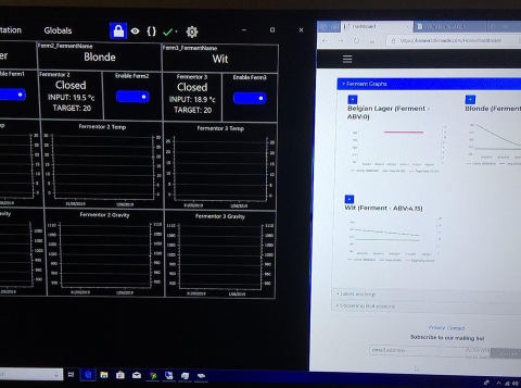
upload_2019-8-29_23-3-48.png


Brewers Chronicle provides a dashboard of current ferments with graphs for temperature and gravity readings accessible from anywhere on any device. You can also produce a ferment report which includes temperature, gravity and pH graphs, all your boil session details, and all ferment temperature gravity readings.

If you are using a Tilt or iSpindel device, then you can create a gravity-based ferment temperature schedule. Part of the sync'ing process passes down the latest calculated target temperature based on received gravity readings and applies it to the relevant device in BruControl. So you then have fully automated gravity-reading controlled ferments.

There is also a feature for receiving SMS's when your ferment temps go out of range from your target temperature. No more brews being cooked over the weekend when you are not there. Not sure how this will work for international numbers as I am based in Australia.

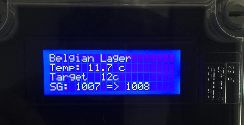
This client install includes LCD's fitted to the Arduino enclosure so you can geek out on values right next to your fermentor.
upload_2019-8-29_23-4-24.png


So I see a really good fit between BruControl and my website. BruControl fully controls all local operations, but passes out all the historical and reporting data to Brewers Chronicle.

At this stage I don't have any documentation on the setup, but it a few global variables per fermentor and some fairly basic scripting. My windows service does the bulk of the work.

I am planning on producing documentation next month for the integration. I'll be looking for a couple of people to trial it out, so will post here when I'm ready.

Thanks,
Angus.

PS: Hope you don't mind the massive advertisement, @BrunDog
 
Last edited:
You don't need an RP-3 board, but we offer them to make wiring easier. You can stack these I suppose to get groups of 4. You do need to buy the amplifiers, as a basic micro-controller cannot read RTD's natively via its analog-digital converter. These amps do this and perform well.

How many milliamps does a single max board use? I tried searching but could not find it, assuming 4 will be safe on a Mega's 5v regulator..

Also, they look to say "3-5v", does the SPI voltage differ between interfaces, if I power them with 5V, will the spi signal burn up a ESP/Feather/GrandCentral (I have to think they wont, because 3.3v RPi users use them all the time)

if you ever update the RP3 to be a feather board adapter, make it fit inside a "Cantex 5133380" 2-gang PVC electrical box ;-)
edit: and see if you can stack 8 of them like DIMM's on a motherboard, maybe using 90 degree headers?
 
Last edited:
Thanks, your help is appreciated and would like to take you up on your kind offer. I am in the process of learning how to use Node-Red, and I posted earlier, I am experimenting running Win10 and BC on a RPI 3B+, and trying to tweak as much latency out of build 1903 as I can. I am not new to Linux, starting with 0.99 p 11 ('93) and Slackware. I am not as familiar with the inner workings of Windows, nor how to integrate Node-Red into BC. Scripting is next in the RPI-BC mix.
Sure, I'm using Node-Red, kind of an IoT middleware, which is free and typically already installed on a Raspberry Pi (Linux), though it can run on Windows and I believe Mac as well. If you are not familiar with Linux, I would recommend running on your BC computer (https://nodered.org/docs/getting-started/windows). From there, you can create a drag and drop workflow with minimal coding. That's really a high level overview of it, so if its a path you want to go down, PM me and I can help you through some of the technical parts of it.
 
The Max take in 5 v and then have an on board regulator down to 3.3v if I read it correctly. I was reading adafruit specs when I saw that. It was explained that you could "pull" 100 ma 3.3v off the Max 3Vo Pin.

Power Pins:
  • Vin - this is the power pin. Since the chip uses 3 VDC, we have included a voltage regulator on board that will take 3-5VDC and safely convert it down. To power the board, give it the same power as the logic level of your microcontroller - e.g. for a 5V micro like Arduino, use 5V
  • 3Vo - this is the 3.3V output from the voltage regulator, you can grab up to 100mA from this if you like
  • GND - common ground for power and logic
 
Good deal!

Just purchased this and a few other items. Looking to buy the power supplies next, at this point I don't need too much high voltage stuff, just powering mainly solenoids and monitoring glycol reservoir.. Tho I will purchase a 240v contactor for the cold storage AC control. I guess with that being said Ill need to bring in 240v to the panel rather than 110v.

https://www.amazon.com/ALITOVE-Tran...+supply+10amp&qid=1566957727&s=gateway&sr=8-1
24V to power the solenoid valves. These calc out at about .33amp/per. At 12 fermenters this is approx 4amp plus a bit of draw on the relays. I think this is well suited.

https://www.amazon.com/PHEVOS-Universal-Switching-Raspberry-Computer/dp/B07BQFQK63/ref=sr_1_7?keywords=5v+dc+power+supply&qid=1566957147&s=gateway&sr=8-7&th=1
12V/10A I think is overkill. My current thought is this will only supply power to the interface. Go big or go home? Should hurt to oversize these correct?

Let me know if I'm missing something, I'm assuming the interface will supply the 5a output for the coil side of the 24v relays for solenoid valves and for the 240v contactor for AC.
https://www.amazon.com/SainSmart-10...v+coil+relay&qid=1566950879&s=gateway&sr=8-16


I would also get a 24 v to 5v Buck transformer.

amazon.com/EPBOWPT-Converter-Regulator-Supply-Transformer/dp/B01M03288J/ref=sr_1_6?crid=1ISE5IYK4KH5T&keywords=5v+buck+converter&qid=1567110205&s=gateway&sprefix=5v+Buck%2Caps%2C183&sr=8-6


Tie ALL of the grounds together on the Power supplies and the boards. I use a standard Ground bar that goes in a Circuit Breaker box.
 
The Max take in 5 v and then have an on board regulator down to 3.3v if I read it correctly. I was reading adafruit specs when I saw that. It was explained that you could "pull" 100 ma 3.3v off the Max 3Vo Pin.

Power Pins:
  • Vin - this is the power pin. Since the chip uses 3 VDC, we have included a voltage regulator on board that will take 3-5VDC and safely convert it down. To power the board, give it the same power as the logic level of your microcontroller - e.g. for a 5V micro like Arduino, use 5V
  • 3Vo - this is the 3.3V output from the voltage regulator, you can grab up to 100mA from this if you like
  • GND - common ground for power and logic

still looking for how much current the board draws when an RTD is connected and it is operating... it will be taking this from the 5v pin or regulator on the interface.
 
I would also get a 24 v to 5v Buck transformer.

amazon.com/EPBOWPT-Converter-Regulator-Supply-Transformer/dp/B01M03288J/ref=sr_1_6?crid=1ISE5IYK4KH5T&keywords=5v+buck+converter&qid=1567110205&s=gateway&sprefix=5v+Buck%2Caps%2C183&sr=8-6


Tie ALL of the grounds together on the Power supplies and the boards. I use a standard Ground bar that goes in a Circuit Breaker box.

Can you explain what this would be use for? I haven’t had a chance to read through your pdf.. hopefully soon.
 
Should I step down my 12v from 24v transformer or have separate 120v to 12v and 120v to 24v step down?
 
Good deal!

Just purchased this and a few other items. Looking to buy the power supplies next, at this point I don't need too much high voltage stuff, just powering mainly solenoids and monitoring glycol reservoir.. Tho I will purchase a 240v contactor for the cold storage AC control. I guess with that being said Ill need to bring in 240v to the panel rather than 110v.

https://www.amazon.com/ALITOVE-Tran...+supply+10amp&qid=1566957727&s=gateway&sr=8-1
24V to power the solenoid valves. These calc out at about .33amp/per. At 12 fermenters this is approx 4amp plus a bit of draw on the relays. I think this is well suited.

https://www.amazon.com/PHEVOS-Universal-Switching-Raspberry-Computer/dp/B07BQFQK63/ref=sr_1_7?keywords=5v+dc+power+supply&qid=1566957147&s=gateway&sr=8-7&th=1
12V/10A I think is overkill. My current thought is this will only supply power to the interface. Go big or go home? Should hurt to oversize these correct?

Let me know if I'm missing something, I'm assuming the interface will supply the 5a output for the coil side of the 24v relays for solenoid valves and for the 240v contactor for AC.
https://www.amazon.com/SainSmart-10...v+coil+relay&qid=1566950879&s=gateway&sr=8-16

I'm not following... you have a 12V power supply but 5V relays. These are not compatible.
 
How many milliamps does a single max board use? I tried searching but could not find it, assuming 4 will be safe on a Mega's 5v regulator..

Also, they look to say "3-5v", does the SPI voltage differ between interfaces, if I power them with 5V, will the spi signal burn up a ESP/Feather/GrandCentral (I have to think they wont, because 3.3v RPi users use them all the time)

if you ever update the RP3 to be a feather board adapter, make it fit inside a "Cantex 5133380" 2-gang PVC electrical box ;-)
edit: and see if you can stack 8 of them like DIMM's on a motherboard, maybe using 90 degree headers?

They don't use much power but I am not sure offhand. I think you can use 4 but I would not use Wi-Fi shield simultaneously. Don't power the boards with 5V on a 3.3V interface - power them with same input voltage.

90 degree headers (assuming we can find)... GREAT idea. Turn them on edge for higher density. I like it!
 
Are you kidding?!? This is super cool!! It was primarily your request that led to the communication protocol being added!

Once I have the documentation complete I'll create a new post to avoid a bunch of Brewers Chronicle content in your BruControl thread.

Thanks again for the API. It's some impressive work.
 
They don't use much power but I am not sure offhand. I think you can use 4 but I would not use Wi-Fi shield simultaneously. Don't power the boards with 5V on a 3.3V interface - power them with same input voltage.

90 degree headers (assuming we can find)... GREAT idea. Turn them on edge for higher density. I like it!

I looked... I don’t think 90 degree long-edge headers exist.
 
I looked... I don’t think 90 degree long-edge headers exist.

probably have to put the 90 degree male pin headers on the MAX boards so they plugged straight in.. if you had the boards horizontal and stacked vertical and on din rail, would take up very little room but screws might be hard to reach.. maybe side slotted thing to hold the boards, connect RTD wires before inserting like a memory card...
 
OK, anyone have the RP-3 working with a ESP32?

Fresh v45C firmware burn
have ESp32 and mega side by side and I move the data pins from one to the other(and try resetting power to the RP-3). Mega reads the RTD great, but no reading on the ESP32...

Code:
Function    Mega    ESP32       wire color
Clock        D52    GPIO14    P14    green
MISO/SD0    D50    GPIO12    P12    orange
MOSI/SDI    D51    GPIO13    P13    yellow

CS1        D14    GPIO27    P27    blue 
(also tried 17 and 26)
 
ESP32 wiring map... what pins are the SCK/MISO/MOSI (to connect to SCLK/SDO/SDI on the RP-3)?

The v1.1 wiring map says: "R = RTD Input (via SPI board). Wire CS pin from each individual boards to these pins only. Other board pins wired in parallel ‐ see RTD schematic."

I have tried:
14/12/13(above)
18/23/19 http://forum.fritzing.org/t/esp32s-hiletgo-dev-boad-with-pinout-template/5357
6/7/8 (hooking 6 to clock shuts off unit...)

it looks like they are set by the firmware.. would appreciate it being in the interface map...
 
You can't use the 5V from the interface to power the coils - it will take too much current. Either use a separate PS or a buck converter from your 24 or 12V supply.
Ok I’ll get one on order. I’m not sure how to proceed using this component across the various 5v power outs from interface.
 
Ok I’ll get one on order. I’m not sure how to proceed using this component across the various 5v power outs from interface.


First, double check and make sure your solenoids are 24V DC instead of 24VAC... Then get a 24VDC contactor(SIEMENS 3RT1035-1B on eBay will do 40A) , and use this relay board: https://www.amazon.com/gp/product/B07BLWZQZB (also powered by the 24V DC and the interface just supplies the switching signal)

The 12V will power the interface, but if you put much load on the output pins, the 5V regulator will burn up.. the same link as your power supply, the 5V-5A one for $11.99 would be better, you carefully adjust it up to 5.2V and you will not overheat the 5V regulator.

*note: you may be able to carefully lower the voltage on your 12V unit and see how low you can get it, if you can get it to 9V or lower, that would also work, I doubt it will go that low but worth a try, just move it back to where it was if it doesn't.... and report back here with results, please!)
 
Ok I’ll get one on order. I’m not sure how to proceed using this component across the various 5v power outs from interface.

The relay board you listed above uses 15-20mA driver current to power each coil . The one listed by @clearwaterbrewer above is a better fit as it uses a 5mA trigger.

FYI... Pg 14 BruControl User Manual v1.1

"Another consideration is ancillary hardware requirements current needs. The pins from the interfaces can source (provide positive voltage) or sink (provide a path to ground), but have limited voltages and currents they can accommodate. For example, the Arduino MEGA has a per-pin limit of 15mA, but it is recommended devices which only use 5mA or less are implemented. In this example, a solid-state relay (SSR) should be selected which only requires 5mA or less at 5VDC to be triggered. All interfaces have per pin and maximum total current limitations – the manufacturers specification sheet should be consulted."
 
Last edited:
Also, on that 24 VDC coil board, if you use Active High mode, it will not switch with 5V input. That is why I quoted the Electronics Salon board(s) above - they will switch with a 5V input even if the coils are 24V. I don't know why anyone would want to switch a 24V relay with 24V, but that's how these knock-offs are made.

Bottom line: Either use a 5V power supply and switch 5V coils with active high, or use active low relays.
 
Feature request: I’d love to be able to graph the target temp. I guess this would be the target a PID, hysterisis, or Dead band element. Could this possible in the future?
 
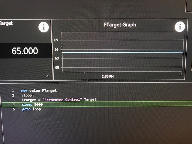
Would be a tad of a workaround, but if you create a variable in a script which occasionally updates itself to follow the value of the target. Then create an inspector to show its value (and hide it if you don't want it on your workspace), then edit its value. Like so:

Pic.jpg
 
Last edited:
A Few of Questions:

What would you use the Calibration Tab for? The only property that you could calibrate is the Output from what I see. The "Calibration" of a PID is in the Ki, Kp and Kd.

Reversed: Should this really be labeled "Heating"? In other words, if reversed is On, you are heating something. If it is Off, you are cooling something. Is this correct?

What is the use of the display of the Output? I know (not really but I like to act like I do) it displays the proportional value that is commanded. How do you use that practically?

In addition if you use a script to pull up the InputPortID, I get a big hexadecimal number (bf43b437-129a-4fbd-a127-172d68e492cc). How is that useful?

I'm assuming everything you are asking is in the context of a PID? Answers below are specific to that.

Calibration is used to modify the raw value into a user value through an Element. I calibrate mine on my PID elements for example, to display power output or net duty time (0 - 100%). Your assessment of PID coefficients isn't quite accurate - these parameters change the performance of the PID, not help achieve a desired or expected value.

No, "Reversed" should not be "heating" since a PID can do more than heat or cool, depending on what it is connected to. No rules on what you use your PID's for (might want to control a valve for example).

Regarding the display, it's telling you the calculated result of the PID, again in raw format. See above on making this value mean something to you.

Don't read InputPortID's in scripts. This property should be written only, to change the port number of the input used for a PID. I suggest you do not use this property at all as it would be for very advanced applications.
 
Would be a tad of a workaround, but if you create a variable in a script which occasionally updates itself to follow the value of the target. Then create an inspector to show its value (and hide it if you don't want it on your workspace), then edit its value. Like so:

View attachment 642246

One caveat (unless a fix has been released @BrunDog?) is you must locate your inspector on the same workspace as your graph. It took me a while to work out why my "Display" workspace graph was not updating when the inspector was displaying updated values on a "Variables" workspace

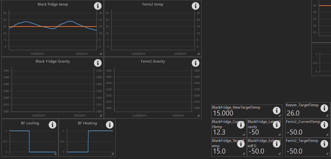
I've done this to display current temperature (this is actually built into graph) and target temperature values on same graph, and to also display current gravity on another graph. Unfortunately I've not got any active ferments at the moment, so no gravity values being fed through from Brewers Chronicle.

Ignore the new "_NewTargetTemp" variable as that is for feeding a new target through via the API data exchange.
upload_2019-9-1_8-14-0.png


In the graph properties, you set the source to your variable name.
upload_2019-9-1_8-15-55.png


And scripting
upload_2019-9-1_8-19-25.png


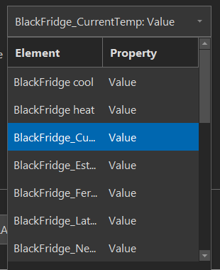
And one thing which bugs me a little is the width of the drop-down control for selecting chart source. Can the drop-down be expanded to be wider than the textbox control? Expanding the "Element" column very time is a bit painful.
upload_2019-9-1_8-23-6.png
 
Correct... this has not been fixed yet. It's in the queue though!

We are working on some bug fixes, moving logs and data into a database (rather than files), and website front-end. Going to try for more frequent, incremental updates rather than less frequent big ones, so these will get released in stages.
 
I'm assuming everything you are asking is in the context of a PID? Answers below are specific to that.

Calibration is used to modify the raw value into a user value through an Element. I calibrate mine on my PID elements for example, to display power output or net duty time (0 - 100%). Your assessment of PID coefficients isn't quite accurate - these parameters change the performance of the PID, not help achieve a desired or expected value.

No, "Reversed" should not be "heating" since a PID can do more than heat or cool, depending on what it is connected to. No rules on what you use your PID's for (might want to control a valve for example).

Regarding the display, it's telling you the calculated result of the PID, again in raw format. See above on making this value mean something to you.

Don't read InputPortID's in scripts. This property should be written only, to change the port number of the input used for a PID. I suggest you do not use this property at all as it would be for very advanced applications.


I immediately thought of converting the raw output to a percentage, but I was thinking of what value that is on an Heating Element. I want it to achieve the Target. I really don't care if it is 49.8 % or 127 raw value. I am not sure know what the Raw Value or even a percentage does. I can also see changing the Input sensor of a PID but since they are physical sensor, I would not likely be doing that. Of Course , others may do that. I still do not know if you are using a PID control to heat water, if you want that reversed? If you are controlling a Proportional valve, what is reversed? Do I reverse or not? Or with a valve is it immaterial. I was thinking of my cooling water where I pump cold water through a Plate chiller to obtain my desired pitch temperature. I would be cooling so I would think Reversed "Off" if I use a Proportional valve?
 
A few of requests on the PID Control Element:

1. A Choice for Raw to Percentage Calibration on the Calibration of on Output in the Calibration Pull Down Menu.
2. "Input:Temp" remove these automatic prefixes from the Element. Since a Prefix and Suffix on the Input Element follow to the PID Control, you can add already.
3. Add Input and Target as Properties in the Pull Down Property Menu of a PID Control. Not necessarily for calibration but for Prefix or Suffix You cannot add a suffix to the Target

4. Default so Pi, Pd, Pk set to defaults for a normal brewery..
5. Better explanation of Reversed
Property
 
4. Default so Pi, Pd, Pk set to defaults for a normal brewery.

What's normal? Full volume mash, sparging, 10 gallon, 10 barrel, RIMS, HERMS, counterflow HERMS, Kettle RIMS? Controlling a heating element, control valve, pump speed? Variable being controlled a temp, flow rate, temperature difference, level, pressure? How far away in the system is the control point from the feedback, how much slack is there?

There's no normal. Normal makes too many assumptions about the end user.
 
Back
Top