BruControl: Brewery control & automation software

Homebrew Talk - Beer, Wine, Mead, & Cider Brewing Discussion Forum

Help Support Homebrew Talk - Beer, Wine, Mead, & Cider Brewing Discussion Forum:

This site may earn a commission from merchant affiliate links, including eBay, Amazon, and others.
Also, on that 24 VDC coil board, if you use Active High mode, it will not switch with 5V input. That is why I quoted the Electronics Salon board(s) above - they will switch with a 5V input even if the coils are 24V. I don't know why anyone would want to switch a 24V relay with 24V, but that's how these knock-offs are made.

Bottom line: Either use a 5V power supply and switch 5V coils with active high, or use active low relays.

yes, that is correct... I have not been able to find a relay board that is powered with 24VDC and takes a 3-5V trigger... I personally would love to use fewer power supplies...
 
What's normal? Full volume mash, sparging, 10 gallon, 10 barrel, RIMS, HERMS, counterflow HERMS, Kettle RIMS? Controlling a heating element, control valve, pump speed? Variable being controlled a temp, flow rate, temperature difference, level, pressure? How far away in the system is the control point from the feedback, how much slack is there?

There's no normal. Normal makes too many assumptions about the end user.

I dunno, most of the discrete PID's I have bought (auber, sestos, etc) come with preset values that are 'OK' for brewing...
 
A few of requests on the PID Control Element:

1. A Choice for Raw to Percentage Calibration on the Calibration of on Output in the Calibration Pull Down Menu.
2. "Input:Temp" remove these automatic prefixes from the Element. Since a Prefix and Suffix on the Input Element follow to the PID Control, you can add already.
3. Add Input and Target as Properties in the Pull Down Property Menu of a PID Control. Not necessarily for calibration but for Prefix or Suffix You cannot add a suffix to the Target

4. Default so Pi, Pd, Pk set to defaults for a normal brewery..
5. Better explanation of Reversed
Property

1. We are all about flexibility, so we try not to box people in with pre-defined names. I don't know, maybe everyone prefers the safety of boxes? The raw output for a PID is 0-255. If you want that in percent, add a multiplier at 0.392156 (which is 100/255). Or if simpler, add a multiplier at 100 and a divider at 255 if you want it to be easy. Because: raw * (100 / 255) is the math to get to a percent number. Perhaps you don't want percent power, perhaps you want power in watts? Then add a multiplier of 5500 and a divider of 255 (assuming 5500W element).

2. Not following you here. The PID shows the input value with prefix and suffix to have all the information needed in one place. But perhaps you mean something different?

3. Also not following you. The input is already a pull-down. The Target is a numerical value. You can add a prefix or suffix to the target.

4. As @TexasWine mentioned, there is no such thing as a default. The manual offers some starting numbers for a basic brewery but as I mentioned above, a PID does not need to be tied to a pot of boiling liquid. Coefficients for heating liquids are fairly forgiving - if the PID were resolving flight power in a drone, that's a different tuning animal.

5. Reversed is reversed output. If the calculation leads to a value of 75, it will now be 255 - 75, or 180. Think about it this way: For a heating application, if the target is 100 and the input is 80, you want the PID to calculate an output (full high number) to power a heater to increase the input toward the target. If however you are in a cooling application and the target and input are the same, you want no power to drive a cooling circuit. That is what reversed is for.

I hope these make sense. LMK if not!
 
What's normal? Full volume mash, sparging, 10 gallon, 10 barrel, RIMS, HERMS, counterflow HERMS, Kettle RIMS? Controlling a heating element, control valve, pump speed? Variable being controlled a temp, flow rate, temperature difference, level, pressure? How far away in the system is the control point from the feedback, how much slack is there?

There's no normal. Normal makes too many assumptions about the end user.

That is true that each can set his own, but you need a starting point. We do have new BruControl Brewers that may be new to PIDs. In the manual it gives some values:

"However, for a small scale brewery, starting values of Kp = 30, Ki = 1.0, and Kd = 5 is a good starting point."


I would generally say that a lot of the manual is at too high a level for new people. It explains stuff, but requires a base knowledge that the reader may not have.

Don't get me wrong. I think that BruControl gives you a lot of control over something like a BCS. But that comes at a price in complication. I do know that Kp = 0, Ki = 0, and Kd = 0 (the defaults now), are not going to work. I will start with the "normal" ones.

PIDs can be very complicated and there is a whole profession dealing with "tuning". I am coming from the BCS and there are defaults that work very well for a small Brewery there. All I am suggesting is for someone who does not know a lot about the Ki, Kp, and Kd (including me), have a starting point. I am requesting this so that a newbie (like me) has at least a point to start. I had to dig into the manual to find it. Also sometimes the TLAR (That Looks About Right) (Kp = 30, Ki = 1.0, and Kd = 5) method rather than the Precision Method (PID Tuned) work just fine for a lot of people.

I did play a lot with PID tuning with the BCS and found it was a lot of work for little return with their defaults. Generally I am worried about the Mash and Fermentation and within 1 degree is adequate for me, although with the BCS I get it very steady on the Mash. I do not have proportional valves yet for the Glycol so I may need to tune those when I do that. I do not Fy Sparge so I do not need any precision there (although the Temp + or - 5 F would be fine regardless). I also plan to have a proportional valve for my cooling water to my plate chiller. Right now I manually control the flow.
 
Looking for help getting my license reactivated. Both old pc and new pc show that the license is inactive and cannot be activated. I know it can only be on one pc. Sent an email trying to get it released so I could activate on new pc.
 
I also plan to have a proportional valve for my cooling water to my plate chiller. Right now I manually control the flow.

I have been attempting this for over a year, on and off without the success I wanted... I don't know if it is the clamping or the limit on how small the values can be, I am back at manual for my Johnson valves, and hoping to find time t try again... my stuff starts back on post 1540, and starts back up on post 1955 I set up a script that went through different values, but if I remember right, the issue was that I could not put in a small enough Ki to get the valve to not overreact...
 
PIDs can be very complicated and there is a whole profession dealing with "tuning". I am coming from the BCS and there are defaults that work very well for a small Brewery there. All I am suggesting is for someone who does not know a lot about the Ki, Kp, and Kd (including me), have a starting point. I am requesting this so that a newbie (like me) has at least a point to start. I had to dig into the manual to find it. Also sometimes the TLAR (That Looks About Right) (Kp = 30, Ki = 1.0, and Kd = 5) method rather than the Precision Method (PID Tuned) work just fine for a lot of people.

My thoughts on this is that one must first understand what each of the 3 values (Kp Ki Kd ) mean and how they relate to one another in a mathematical equation to perform a desired effect. Like yourself I am trying to understand the concept of a PID ( I'm new to this also) and what numbers to tweak to obtain this effect. I found this site https://www.csimn.com/CSI_pages/PIDforDummies.html and it helped me grasp at a basic level the concept of what a PID does and found I was able to refer to the User Manual and the examples provided with a lot more clarity because understanding the relationship between each of these values as opposed to plugging in numbers and hoping it works in the end. The manual I believe offers a starting point but each user will have his/her own application (heating and holding a mash at a certain temp, adjusting a proportional valve open/close etc..) it would be difficult to slap in one set of numbers does all. This is why I say understanding the basic concept is a starting point.
I wont say I totally understand the whole PID concept and able to do fine tuning of a PID controller and getting it perfect, but I am clearer on the process behind it and the interaction of its values to achieve a predictable result.
 
Last edited:
My thoughts on this is that one must first understand what each of the 3 values (Kp Ki Kd ) mean and how they relate to one another in a mathematical equation to perform a desired effect.

I asked for the code that BC uses for PID back in March on post 2035 so I could understand it better, and I supplied the version I found on arduino.cc as a reference, I do not recall the actual BC code section ever being supplied...
 
I don’t think that posting the specific code will help you understand. There are variable names and memory locations that once taken out of context, will make little sense. The code does not use the published PID library, but it is functionally identical.

I will assure you though that the math the algorithm calculates is correct and is just like any other PID. PID math is actually not complicated at all - it’s four basic computations: a proportional multiplication, an integral multiply/add, a derivative subtraction/multiplication, and then these three are added together.

IIRC you were not able to get the BC PID to behave like a dedicated unit, but IMO there should be no reason it won’t. I wonder if PID is the right algorithm for what you are trying to do - there are likely better ones (like deadband). I’m happy to help you get it going but we should probably offline it from here.
 
There are engineers that do nothing other than PID Tuning for a career. Obviously ClearWaterBrewer is not getting his desired results even with the tuning. I know that the BCS PID Control works very well out of the box for heating strike water, a Herms bath, Sparging and RIMs. What I want is something I can wire and get to brewing. That why a starting point is good. As I said earlier, I did experiment with PID Tuning on the BCS but it was a lot of effort for almost no gain. I do not know what PID forumla the BCS or BruControl use or even if there are different ones. I should find out this week when I get it wired.
 
There are engineers that do nothing other than PID Tuning for a career. Obviously ClearWaterBrewer is not getting his desired results even with the tuning. I know that the BCS PID Control works very well out of the box for heating strike water, a Herms bath, Sparging and RIMs. What I want is something I can wire and get to brewing. That why a starting point is good. As I said earlier, I did experiment with PID Tuning on the BCS but it was a lot of effort for almost no gain. I do not know what PID forumla the BCS or BruControl use or even if there are different ones. I should find out this week when I get it wired.

it works great for PWM heating or really any thing where the output can be full on or full off for a little bit without hurting anything... in a cooling loop valve, that is a deal killer... not all PID's act the same, not all use the same calculations... not all treat the variables the same...
 
Sorry to beat a dead horse, I'm still learning here. I want to make sure I understand the circuitry as well as a comparison between the two relay boards...Please confirm

Option 1: $50.00

ELECTRONICS-SALON DIN Rail Mount 8 SPDT Power Relay Interface Module, 10A Relay, 12V Coil. - Power this board with 12v supply, eliminating the need for a 5v power supply. Coils can trigger direct from 5v interface because coils have a low mA draw. I can use my 24v power supply through contacts to solenoid valves. This config will be "active high".

Option 2: $22.00
NOYITO 8-Channel Relay Module High Low Level Trigger with Optocoupler Isolation Load DC 30V AC 250V 10A for PLC Automation Equipment Control Industrial Control Arduino (8 Channel 5V)- This board will require a 12v to 5v buck transformer (or a separate 5v power supply) because the supply and coil must be of equal voltage. Coils can trigger direct from 5v interface because coils have a low mA draw. I can use my 24v power supply through contacts to solenoid valves. This config will be "active low".

I understand the 5v output on interface can be burned up if too much current draw is applied. Both boards above will not exceed this draw providing they are NOT powered by interface.

If my assumptions above are correct, I can do option 2 for $22 and option 1 for $50. Are there components missing in either to make this a fair comparison? Am I headed down the right path here?
 
it works great for PWM heating or really any thing where the output can be full on or full off for a little bit without hurting anything... in a cooling loop valve, that is a deal killer... not all PID's act the same, not all use the same calculations... not all treat the variables the same...
That's correct that not all PIDs act the same. From my experience the BCS algorithm acts very similar to BruControl. I was able to use the same settings from the BCS in BruControl with negligible differences in overshoot and settling time.

Some of the discrete PIDs use "fuzzy logic" and other more advanced algorithms on top of the basic PID algorithm for better control.

As an example I used to run a discrete PID before using a BCS. The coefficients that the PID auto tuner calculated worked great, but when I tried to copy them over to the BCS it had a lot more overshoot and ripple than the discrete PID. After manually tuning I got to a similar response with vastly different coefficients.

I have found from writing my own Arduino algorithms for slow heating algorithms like brewing, sous vide, meat smoker, etc. that using a hybrid deadband/PID algorithm works better at avoiding integral windup and improving settling time. In this case I end up using a higher Ki gain than I would with a straight forward PID algorithm. To implement this I set the output to 100% for the outer band. For the inner band I use the PID algorithm to calculate the output, and there is no actual deadband.
 
it works great for PWM heating or really any thing where the output can be full on or full off for a little bit without hurting anything... in a cooling loop valve, that is a deal killer... not all PID's act the same, not all use the same calculations... not all treat the variables the same...

Trust I am not trying to get into a battle on this... but I wan't to remove any doubt about PID algorithms. I'm sorry, but your statements are not accurate.

All PID controllers ARE the same and use the same calculations, assuming they are just doing PID calculations. Otherwise they are not pure PID controllers. So in terms of different vendors, there may be differences, but those are additions or modifications to the pure PID loop. The BC implementation is a pure PID - there is no fuzzy logic or variations.

Your tuning needs to be very slow... basically very little P, very little if any D, and a small dose of I.

Edit: For the record, I did not see @crane's response when I wrote mine!
 
if they are the same, why does Auber explicitly say theirs are different in their manual?
upload_2019-9-1_17-50-36.png
 
I am still confused over the Reversed switch in a PID Control Element.

The Manual:
"The ‘Reversed’ switch inverts the direction the target is trying to be achieved from. This switch would be disabled for applications where the output should be increasing as the input signal falls further below the target, such as in heating applications."

This is what it looks like:
reversed on or off.png


I am assuming that disabled means "OFF"?
So you want it OFF for "heating" and ON for "cooling" as a general rule?

If I am heating my strike water with a PID Control, I want it "OFF"?????
 
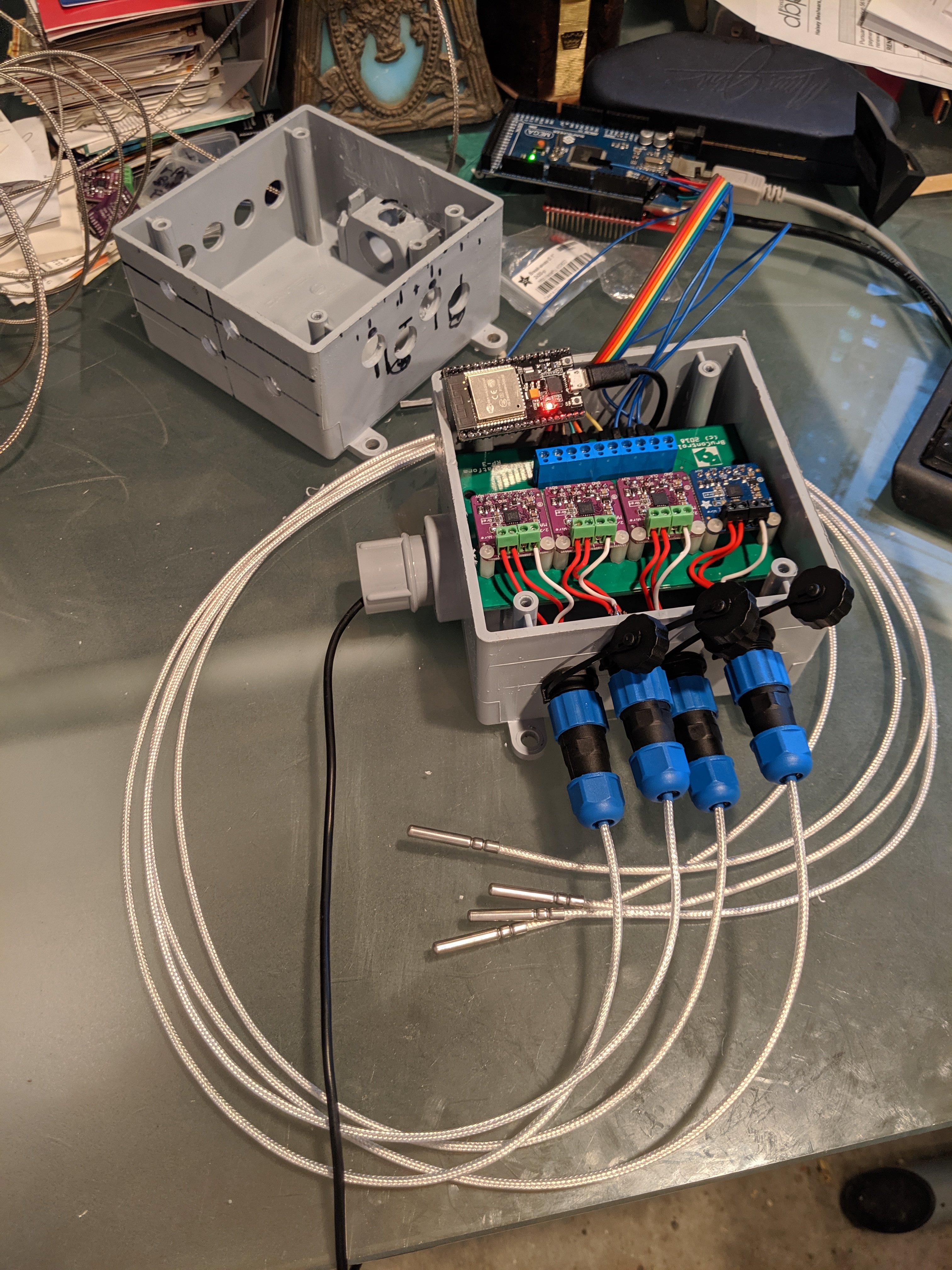
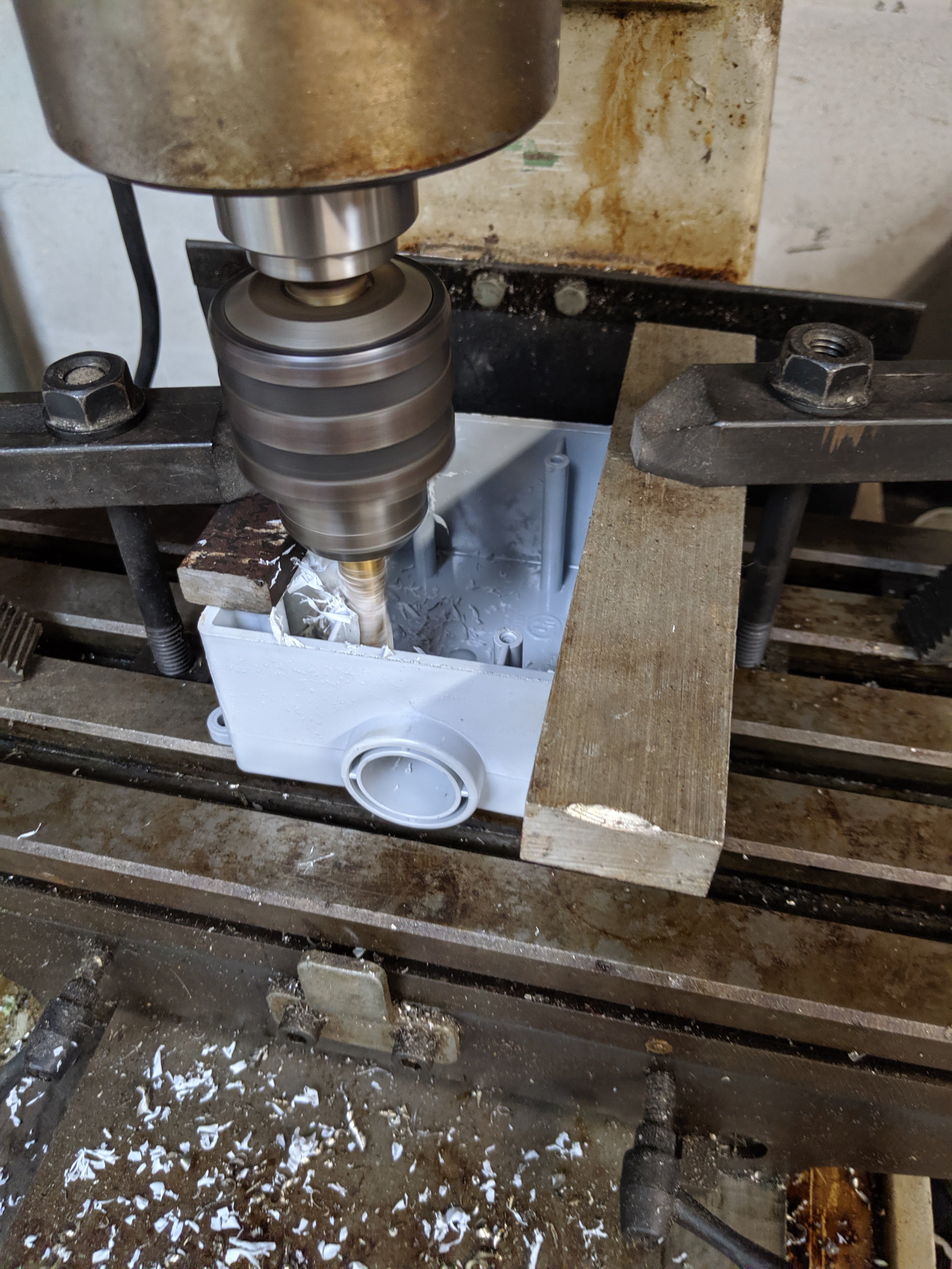
RP-3 mounted in a Cantex 3/4" FSE box ($5.58 ad Home Depot). I milled the inner posts down and dis some testing of connector locations by using one box as a tester... just have to get the ESP SPI working to the RP-3...
IMG_20190901_174446_1.jpg


IMG_20190901_161101.jpg
 
I am still confused over the Reversed switch in a PID Control Element.

The Manual:
"The ‘Reversed’ switch inverts the direction the target is trying to be achieved from. This switch would be disabled for applications where the output should be increasing as the input signal falls further below the target, such as in heating applications."

This is what it looks like:
View attachment 642460

I am assuming that disabled means "OFF"?
So you want it OFF for "heating" and ON for "cooling" as a general rule?

If I am heating my strike water with a PID Control, I want it "OFF"?????

should be easy to test, if you have it wrong, it will not have you heater on when the temp is below you set-point... but if it is above the set-point, it will runaway...
 
if they are the same, why does Auber explicitly say theirs are different in their manual?
View attachment 642459
As you can see auber is stating that they are not using just a straight forward PID algorithm. They use fuzzy logic on top of the standard PID algorithm. Brucontrol, BCS, and the Arduino PID library do not use fuzzy logic. They use the straight forward basic PID implementation, so the coefficients for an auber PID will not behave the same in BruControl.
 
OK, I set up my previous test, something changed since March, I can actually get a smooth line now... that right half of the graph, that was *impossible* to not keep from slamming to zero before...

I could not get this smooth of a line before... I will try this out in production, but it looks like it will work now...

upload_2019-9-1_18-56-41.png
 
I even entered 0.001 as all three constants and it seemed to get even slower, possibly slow enough for our requirement. I will have to run the debug to watch and see if that low of values are really recognized...
 
I even entered 0.001 as all three constants and it seemed to get even slower, possibly slow enough for our requirement. I will have to run the debug to watch and see if that low of values are really recognized...

0.01 is the lowest coefficient resolution. Try that value and see if it is damped enough.
 
I am still confused over the Reversed switch in a PID Control Element.

The Manual:
"The ‘Reversed’ switch inverts the direction the target is trying to be achieved from. This switch would be disabled for applications where the output should be increasing as the input signal falls further below the target, such as in heating applications."

This is what it looks like:
View attachment 642460

I am assuming that disabled means "OFF"?
So you want it OFF for "heating" and ON for "cooling" as a general rule?

If I am heating my strike water with a PID Control, I want it "OFF"?????

If the input (measured) value is below the target, and you want to drive the measured value higher, you want more positive output (as in a heating application) - this is normal operation. If the measured value is above the target, and you want to drive the measured value lower, you want more positive output (as in a cooling application) - this is reversed operation. Think of "which way do I want to drive the measured value (in this case, temperature)... higher (normal) or lower (reversed).

I wouldn't call it ON or OFF, just not reversed or reversed. But yes, for our brewing application, leave "Reversed" disabled (normal) for heating and "Reversed" enabled for cooling. We don't do much cooling with PID due to the rapid potential switching - but if you were cooling with a Peltier cooler for example, then PID for cooling would work a treat!


Thanks. I do have a Peltier cooler that I was going to try. Stout Tanks has quite a write up on a user who did use them.

and BTW, I did not call them on or off, you did! Ha!
reversed on or off.png
 
Not sure if I am making the PID discussion clearer or if I am confusing, just couldn't keep away. As far as I know there are in general three types of PID control equations, they are called Series, Parallel and Standard (also called Ideal).


Picture1.png


The most used equation or controller type is the standard/ideal (Industry type) but in our world with Arduinos (Brucontrol) and cheaper PLCs (BCS) it’s the parallel we encounter. The Arduino parallel equation is not exactly as the per the diagram but more something like this:


Code:
error = Setpoint - input                          

             cumError += error * elapsedTime            

             rateError = (error - lastError)/elapsedTime


             output = kp*error + ki*cumError + kd*rateError


Before starting to tune it it’s good to know which equation your controller uses. For example, if you have a PID using the standard equation, if you change the proportional gain it will also affect the integral and derivative. With the parallel P, I and D are independent of each other. That’s why with the parallel controller the integral is a gain while on the standard controller it’s given in seconds or minutes pr repeats as it’s a measure on how often to repeat the contribution from the proportional gain(error*kp). Almost the same thing with derivative. That’s why you can’t use the tuning parameters from a standard controller in a parallel controller and vice versa. Take a look at the equation for the standard PID and the typical Arduino equation you will see that the integral is inverse on the standard equation, to increase integral contribution you have to lower the Ti while on the Arduino you have to raise it (ki). I am not familiar with the Sestos/Auber but the parallel equation is mostly used by software controllers (PLCs) and not discrete controllers.

I have some experience tuning both the standard and the parallel. I experience it’s easier to tune the standard. Maybe it’s because it’s the one I am most familiar with but also since the proportional gain is always the “master” tuning parameter in the standard I feel it’s easier to understand each tuning parameter’s contribution to the output and the relationship between the tuning parameters.

Regardless of the controller type you have, before starting to tune it’s beneficial to know something about the time constant and dead time in your system.

Time Constant is the “how fast” variable. It describes the speed with which the measured input value or process value responds to changes in the controller output. More specifically it represents the time needed for the process value to reach 63.2% of its total and final change. Think high power heating element vs low power heating element or small vs large kettle.

Dead time is the delay from when a controller output signal is issued until when the measured process value is measured/first begins to respond. Think distance between temp sensor and the heating element. If it’s far away the deadtime is larger, and large deadtime makes tuning harder.

As a rule of thumb PID control will struggle and is considered not suited if Dead time:Time constant ratio is close to or above 1.

Picture2.png


When tuning, as a rule of thumb, only use derivative action if you have a large Time Constant in your system(slow system). Also be careful with derivative if you have a low resolution input value as the derivative will interpret the “step” changes in a low resolution input value and act as it is quick process changes. The same applies if you have a noisy input. So if using derivative make sure you filter the input.

Another rule of thumb the faster (the smaller time constant) the process is the more integral action is required. Slower processes require more proportional gain and less integral. For example an HLT or BKL controller will do best with almost only proportional gain while a faster process like RIMS or flow control will need more integral and less proportional.

The integral contribution to the output can be both negative and positive depending if the error is negative or positive. Normally if the output is zero or max then integral stops winding down/up since the output is out of range and then it’s no point in reducing/increasing it further. The Brucontrol PID controller integral seems to wind further down after reaching the lower end of the output range and that is good to know about when tuning and/or using the controller. For example, with my (for the purpose tuned) RIMS my script reduces the RIMS setpoint from strike temp down to mash temp after dough in. It takes some time to get uniform temp through the mash so the wort flowing in the RIMS tube is warmer than the setpoint the first minutes. Since the temp is above setpoint the integral winds down, naturally, and the RIMS controller output is quickly reduced to zero. After a few minutes when temp finally comes below setpoint and there is a heating demand it takes forever for the integral to wind up again so I always have a fairly large undershoot if I don’t help the integral to wind up faster by giving a temporary higher setpoint to create a larger error hence faster integral wind up. Another way to deal with it could be to let the setpoint follow the actual temp until mash temp setpoint is reached and then set the setpoint to mash temp, like:

Code:
If dougin == true

“rims PID” MaxOutput = 0

If “rims temp” value > mashtemp

“rims PID” target = “rims temp” value

else

“rims PID” target = mashtemp

doughin = false

“rims PID” MaxOutput = 255

endif

endif


I have not tested but it will keep the error at zero and the integral will not wind further down.

The same thing does not happen when output is at the higher end of the output range.
 
Not sure if I am making the PID discussion clearer or if I am confusing, just couldn't keep away. As far as I know there are in general three types of PID control equations, they are called Series, Parallel and Standard (also called Ideal).


<snip>

The integral contribution to the output can be both negative and positive depending if the error is negative or positive. Normally if the output is zero or max then integral stops winding down/up since the output is out of range and then it’s no point in reducing/increasing it further. The Brucontrol PID controller integral seems to wind further down after reaching the lower end of the output range and that is good to know about when tuning and/or using the controller. For example, with my (for the purpose tuned) RIMS my script reduces the RIMS setpoint from strike temp down to mash temp after dough in. It takes some time to get uniform temp through the mash so the wort flowing in the RIMS tube is warmer than the setpoint the first minutes. Since the temp is above setpoint the integral winds down, naturally, and the RIMS controller output is quickly reduced to zero. After a few minutes when temp finally comes below setpoint and there is a heating demand it takes forever for the integral to wind up again so I always have a fairly large undershoot if I don’t help the integral to wind up faster by giving a temporary higher setpoint to create a larger error hence faster integral wind up. Another way to deal with it could be to let the setpoint follow the actual temp until mash temp setpoint is reached and then set the setpoint to mash temp, like:

your information helps. some of it has common underlying traits to what I was experiencing. things happening with the integral that were not expected.

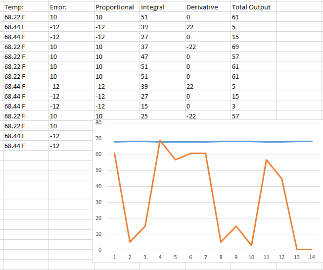
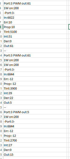
what I noticed since my March tests was that the herky-jerky HUGE changes in output with a tiny change in input from above to below the setpoint are gone. Here is a small set of data in a spreadsheet that I use to import the log data, you can see the wild swings in total output of more than half the output range...:
upload_2019-9-2_8-32-1.png


now it is literally *beautiful* when viewed with the frustration I had before...
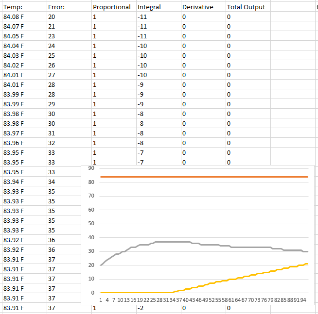
(grey is error, gold is output) sorry it does not have negative error in this sample
upload_2019-9-2_8-41-35.png


I have a spreadsheet that is fairly simple to cut and paste data from the debug into, but cannot attach.
 
your information helps. some of it has common underlying traits to what I was experiencing. things happening with the integral that were not expected.

what I noticed since my March tests was that the herky-jerky HUGE changes in output with a tiny change in input from above to below the setpoint are gone. Here is a small set of data in a spreadsheet that I use to import the log data, you can see the wild swings in total output of more than half the output range...:
View attachment 642540

now it is literally *beautiful* when viewed with the frustration I had before...
(grey is error, gold is output) sorry it does not have negative error in this sample
View attachment 642541

I have a spreadsheet that is fairly simple to cut and paste data from the debug into, but cannot attach.

In the first tests the low resolution input causes the derivative to go crazy. Is it onewire?
 
In the first tests the low resolution input causes the derivative to go crazy. Is it onewire?
it was.. but looking at the data, not sure that matters... that data is taken straight from the debug...

Edit - OK, I see what you mean... yes, so again, I wanted to know the calculations, for example, derivative can be calculated a couple different ways, the more stable is using the angle, not the direct delta-T the previous code on arduino.cc I showed a discussion of this in the comments at post 2035.

upload_2019-9-2_11-0-23.png
 
Last edited:
What are those blue/black connectors?

Looking back at my aliexpress orders, they are the 4-pin Waterproof connector IP68 SP13 from "MannHwa Smart Home Electrical" on aliexpress for $1.54... I drilled 9/16" holes with a step bit, and alternated 3/4" horizontal and the top row 5/8" down and 2nd row 1.25" down... inside is milled out 1.0" deep..

(I don't use four -wire RTD now, but if I did want to, and my three pin are for 1-wire and 2-pin for thermistors for BC) I also have PG21 for power stuff...
 
In the first tests the low resolution input causes the derivative to go crazy. Is it onewire?

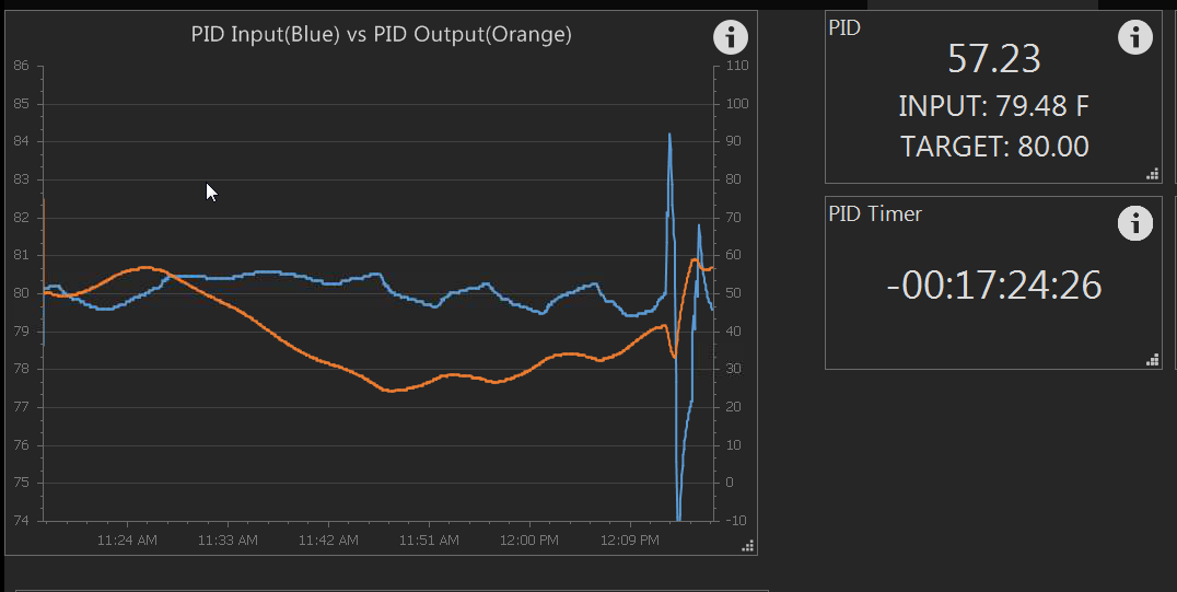
another thought from your one wire comment... analog inputs and RTD inputs have the smoothing factor "Avg Weight"... I changed this to 100% to test, and it was quicker to react as expected(where the blue spikes happen is where it was turned on), but did not go wild or slam to zero... the blue line of temp had wild swings induced by me, but the orange acted as a PID should... I will try to test on a 1-wire next..
upload_2019-9-2_12-17-33.png
 
@smort brings up a valid point - there are several forms which exist. Honestly, I did not realize the standard one is "more typically" used in industry - I was of the mindset that the pure (parallel) variation is the most common implementation, and this is indeed what BC uses. For brewery purposes, this isn't going to matter much. Functionally, they will do the same thing, but tuning principles are a bit different. I personally like the ability to tune each coefficient individually, but to each their own.

So perhaps I should rescind my comment that they are all the same!
 

Latest posts

Back
Top