BruControl: Brewery control & automation software

Homebrew Talk - Beer, Wine, Mead, & Cider Brewing Discussion Forum

Help Support Homebrew Talk - Beer, Wine, Mead, & Cider Brewing Discussion Forum:

This site may earn a commission from merchant affiliate links, including eBay, Amazon, and others.
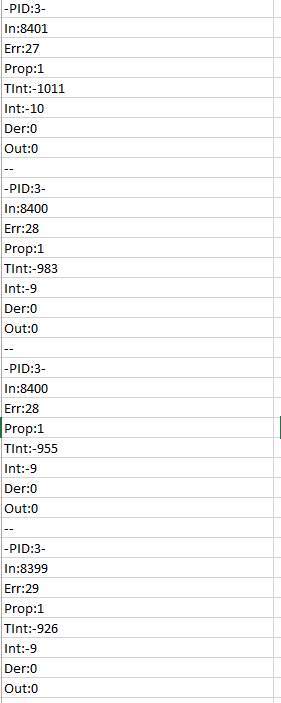
another thing to look at, I am seeing that the debug shows 0.01 temp increments, but my display never shows that small of an increment change... minimum I can get it to jump is 0.05 or 0.06 degrees..... thoughts?

edit: I figured it out, the PID debug is showing the un-calibrated value... doh!

upload_2019-9-2_12-24-5.png
 
Last edited:
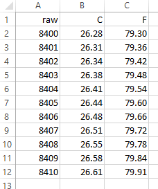
I charted 10 in a row for my own understanding...
upload_2019-9-2_12-42-43.png


in comparison, the onewire jumps from 84.87 to 85.10 when it is flipping back and forth , which is 0.23 degrees, versus 0.06, so basically 4 times more resolution, and 4 times less jump with the RTD...
 
Thinking, a very low priority feature request would be to look at the 1-wire sensor code and see if a 'Avg weight' property, 'calibration' item, or maybe just a behind the scenes smoothing operation could be implemented. Thinking behind the scenes would be required, since it looks like the PID takes the raw value, BC would have to do the smoothing before the raw value is handed to the PID...
 
How would one use a servo with BC? Connect the signal wire of the servo to a PWM output? Are there hardware considerations? I thought I read some may be 500 vs 1000 Hz?

What about a continuous rotation servo?
 
1-wire is a lesson in trade-offs. What you get in ease of wiring/implementation, you lose in speed. You can increase the resolution (not the error) but is makes timing even slower. We picked a resolution we thought was a good balance (11 bit), so that's 0.125 degs C.

We don't have any motor control in, but have contemplated a motor element... what are you looking to do @VinceBrews?
 
Thinking, a very low priority feature request would be to look at the 1-wire sensor code and see if a 'Avg weight' property, 'calibration' item, or maybe just a behind the scenes smoothing operation could be implemented. Thinking behind the scenes would be required, since it looks like the PID takes the raw value, BC would have to do the smoothing before the raw value is handed to the PID...

We could add weight averaging like analog inputs.
 
Automating my hop additions, and motorizing a needle valve on my gas smoker for temperature control...
 
Sorry to beat a dead horse, I'm still learning here. I want to make sure I understand the circuitry as well as a comparison between the two relay boards...Please confirm

Option 1: $50.00

ELECTRONICS-SALON DIN Rail Mount 8 SPDT Power Relay Interface Module, 10A Relay, 12V Coil. - Power this board with 12v supply, eliminating the need for a 5v power supply. Coils can trigger direct from 5v interface because coils have a low mA draw. I can use my 24v power supply through contacts to solenoid valves. This config will be "active high".

Option 2: $22.00
NOYITO 8-Channel Relay Module High Low Level Trigger with Optocoupler Isolation Load DC 30V AC 250V 10A for PLC Automation Equipment Control Industrial Control Arduino (8 Channel 5V)- This board will require a 12v to 5v buck transformer (or a separate 5v power supply) because the supply and coil must be of equal voltage. Coils can trigger direct from 5v interface because coils have a low mA draw. I can use my 24v power supply through contacts to solenoid valves. This config will be "active low".

I understand the 5v output on interface can be burned up if too much current draw is applied. Both boards above will not exceed this draw providing they are NOT powered by interface.

If my assumptions above are correct, I can do option 2 for $22 and option 1 for $50. Are there components missing in either to make this a fair comparison? Am I headed down the right path here?
/\ Need a bump here so I can catch up to you guys..

In the meantime Ive started working on the UI graphics. I want to keep the monitoring screen clean so I will likely move things like graphs and timers to a separate page, perhaps ill use the hide element function.

Interface2.png
 
Sorry to beat a dead horse, I'm still learning here. I want to make sure I understand the circuitry as well as a comparison between the two relay boards...Please confirm

Option 1: $50.00

ELECTRONICS-SALON DIN Rail Mount 8 SPDT Power Relay Interface Module, 10A Relay, 12V Coil. - Power this board with 12v supply, eliminating the need for a 5v power supply. Coils can trigger direct from 5v interface because coils have a low mA draw. I can use my 24v power supply through contacts to solenoid valves. This config will be "active high".

Option 2: $22.00
NOYITO 8-Channel Relay Module High Low Level Trigger with Optocoupler Isolation Load DC 30V AC 250V 10A for PLC Automation Equipment Control Industrial Control Arduino (8 Channel 5V)- This board will require a 12v to 5v buck transformer (or a separate 5v power supply) because the supply and coil must be of equal voltage. Coils can trigger direct from 5v interface because coils have a low mA draw. I can use my 24v power supply through contacts to solenoid valves. This config will be "active low".

I understand the 5v output on interface can be burned up if too much current draw is applied. Both boards above will not exceed this draw providing they are NOT powered by interface.

If my assumptions above are correct, I can do option 2 for $22 and option 1 for $50. Are there components missing in either to make this a fair comparison? Am I headed down the right path here?

Either option 1 or 2 will work. For 2, you could still use Active High.
 
another thought from your one wire comment... analog inputs and RTD inputs have the smoothing factor "Avg Weight"... I changed this to 100% to test, and it was quicker to react as expected(where the blue spikes happen is where it was turned on), but did not go wild or slam to zero... the blue line of temp had wild swings induced by me, but the orange acted as a PID should... I will try to test on a 1-wire next..
View attachment 642562
Do not know if effective or not, but if you use a string data type to set Kp, Ki, or Kd, you can set them to Precision 14 via a Script. If using a value type, the precision is 3. I do not know the code so it may not be effective past an internal Precision. I did see on post about smallest is .01, so that would mean anything past Precision 2 is not effective if that is correct.

EDIT: I realized after playing more that it is characters count and not precision. But it can still accept a Precision 14 number when setting.
 
Last edited:
There are a lot of fields which will accept a long decimal, but these will get rounded on the way to the interface. In the case of the PID coefficients, 0.01 is the lowest value.

Also, you should use string types for text, value types for numbers. The coefficients are numbers, so use value types. We [humans] may automatically read "0.123" as a value, but when this is stored in a string, it is just a bunch of characters that the computer recognizes as text, not a number.
 
Feature request: ability to control typical RC servos. [emoji6]

I think the ability is there, they just operate on a 0-5v output signal... you can control them directly from a Mega because it is 5V, but probably best to use the BC analog amplifier board or a simple transistor setup for other boards, and I also suggest running them from a separate 5V supply... running from the Mega 5V and powering the mega from 12V is probably a BAD idea... Here is a connection example.

For configuration, just use a PWM output... add a 'linear multiplier calibration' of 2.55.. I have done the same thing with great results for a 24vac johnson GGA control valve that uses 0-10v (or 2-10v via 4-20mA through a 500ohm resistor) if your servo has a feedback, you can tie that back to an analog input to monitor position, which I have also done with the johnson valve.

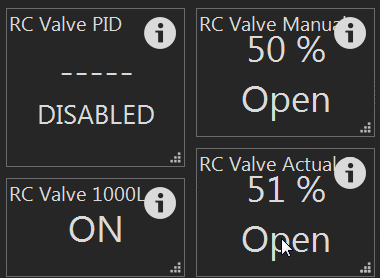
Here is mine, I also have the PID, (either PID or PWM can be enabled on the same output, enabling one disables the other)
I set "RC Valve Manual" to 50, and can watch the slow moving servo move to that point via the Analog input 'RC Valve Actual', here it is at 51, but that is fine and you can tweak the calibrations, I have an offset calibration of -21 and a divider of 9.9 to take the 1024 of the mega down to 100.. it is all that y-mx+b crap
upload_2019-9-2_22-38-28.png
 
PWM is a common way to get an analog-esque signal from a digital source... here is the picture from the link I posted, even has the servo model they are using... are you saying it won't work?? I am 99% sure it will..
upload_2019-9-2_23-11-15.png
 
A true PWM generator tuned to the operational spec for the servo is the goal, but what's going on is far from anything "analog".
The PWM signal is not generated as a voltage - averaged or otherwise - the servo actually looks at the active pulse width to set the motor travel. Typically 1.5ms is center, 1.0ms and 2.0ms are the opposite ends of the scope...

Cheers!
 
And it does appear that the servos expect a different PWM frequency than the ~500 or 1000 Hz of the current PWM outputs. PWM frequencies can be changed, but they will affect multiple pins (those tied to the same timer block.)
 
We'll, I had originally assumed it would, which is why I asked the question in the first place. Here's what I know about RC servos: they use a PWM signal at 50 Hz. The width of the pulse itself usually varies from 1-2ms.

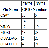
The PWM output from a MEGA/BC is 1000 Hz according to the wiring map.

So it is not obvious to me that it will work (although I'm game to give it a try).

What I thought I understood from @clearwaterbrewer is that we could use an analog output (maybe I misunderstood).

Either way, I have no doubt that it is possible, I just assumed we need the right software/firmware to make it work.

I'll try it in a few days and report back.
 
I am willing to bet that inside the servo, that PWM is converted to an analog level with a simple RC filter.. If you have a servo, why not give it a shot?

People ARE using the Mega to control servos, so it is not like it is going to damage either device...
 
I am not saying that a feature request for allowing the changing the REFRESH_INTERVAL or other settings is not a cool thing to have, lets just see if the default works...

Referencing the BC manual, page 43:
PWM Output (Analog Output)
These are variable devices which command the interface’s pin to be pulsed at a fixed high frequency but with varied pulse widths. These types of devices are noted above under Device Types, list #3. PWM stands for Pulse Width Modulation, which is a rectangular output wave where the ON time and OFF time add up to a consistent period. That period equates to a frequency which is ~500 Hz, ~1000 Hz, or similar, depending on the interface and pin. A PWM value of 50% will create a square wave output, whereas a value of 75% will create an output which is on for 75% of the period, then off for the remaining 25%. The net effect to devices which “average” this output creates the effect of varying power. An analog voltage can be created from a PWM Output with appropriate hardware, such as a low pass filter to convert the PWM Output to an Analog Output. See the Schematics section on BruControl’s website for details. The value along a relative range proportional to the ON time percentage is presented as the Element’s value. By default, that range is 0-255.​

A helicopter article talking about PWM and saying:
The "normal" frequency of this PWM signal is 50 Hz, meaning that 50 times a second, the position of the servo is "updated" or "refreshed". Time wise, that means once about every 20 milliseconds.

This frequency can vary quite a bit between brands and components (most fully compatible), and has no impact on the actual servo position, it only impacts how often that position is updated.
https://www.rchelicopterfun.com/rc-servos.html

The Arduino Servo library supports up to 12 motors on most Arduino boards and 48 on the Arduino Mega.
source: https://www.arduino.cc/en/Reference/Servo

A forum topic on changing frequency and how Arduino uses hardware timers to control PWM pins
https://forum.arduino.cc/index.php?topic=570551.0

Great link on Arduino PWM implementation:
https://www.arduino.cc/en/Tutorial/SecretsOfArduinoPWM
 
Once the frequency starts to get lower, an analog conversion gets much less smooth using a traditional low-pass filter (R-C circuit). So it is possible these servos do not convert the PWM to analog, but track rising edges and clock off of that. In that case, there will be a point where they don't track any longer. The difference between 50 Hz and 1000 is pretty significant. I'll need to order a servo or two to test this.

Otherwise, we will need to add a function to lower the PWM frequency of certain pins. Not a big deal.
 
adafruit seems to sell many servos and has regular and continuous rotation ones which might prove interesting for something like a hop adder... they say "To control with an Arduino, we suggest connecting the orange control wire to pin 9 or 10 and using the Servo library included with the Arduino IDE" so it seems logical if you make changes, to do it to those pins to start, and maybe look at what the Arduino IDE library has in it.. github link
 
Last edited:
Why is it that I can only (1) of each type of device from the "add device" menu? Being that I am controlling various fermenters I assume I need multiple hysteresis output devices. Does this have something to do with not actually being connected to the interface?
 
Why is it that I can only (1) of each type of device from the "add device" menu? Being that I am controlling various fermenters I assume I need multiple hysteresis output devices. Does this have something to do with not actually being connected to the interface?
Are you making sure to set each device to a different interface pin?
 
E
Are you making sure to set each device to a different interface pin?
To date I haven't worried about interface pin since I don't have the physical board, figured I'd perform all this when I'm connected. I did check and each are on the same pin "Port 2" I cannot seem to change this tho. Perhaps I need to connect first then build the UI?
 
I haven't looked to see what Futaba et al have for full rotation servos wrt torque ratings these days, but frankly a hop adder would be better implemented using a stepper motor, which are definitely available (and have been used with BC)...

Cheers!
 
Which value calibrations are needed to display PT100 in Fahrenheit? I imagine I need to add "resistance temperature calibration" what reference resistor?

Does the active low on/off correlate to the electronics-salon board i purchased? Since this board is active high should I use active low "off"?
 
Does the active low on/off correlate to the electronics-salon board i purchased? Since this board is active high should I use active low "off"?

Pg 41 from the manual. "Digital Output These are binary devices which command the interface’s pin to be a high or low voltage. These types of devices are noted above under Device Types, list #1. The state is presented as the Element’s state and will either be ON or OFF depending if the voltage is high or low. High is ~90% and low is ~10% of the interface’s operating voltage (approximate values, depends on the interface’s CPU). By default, when the Device Element is ON, the interface pin’s voltage is high (Active High)."

ELECTRONICS-SALON DIN Rail Mount 8 SPDT Power Relay Interface Module, 10A Relay, 12V Coil

Manufacturers Spec:
Operating Voltage/Current(max.): 12Vdc / 400mA.
Input control signal voltage:
0V - 0.5Vdc, low level, relay not action.
0.5V - 2.5Vdc, unknown state.
2.5V - 24Vdc, high level, relay action.
Input control signal high level current:
2.5V: 0.1mA.
5V: 0.35mA.
12V: 1.1mA.
20V: 1.9mA.

I use the 5VDC Coil version of this relay board and the inputs work fine with "Active Low". (ON)
If you are going to be using SSR's in your build you will need to determine the control signal voltage requirement as per manufactures recommendation.
 
Last edited:
Which value calibrations are needed to display PT100 in Fahrenheit? I imagine I need to add "resistance temperature calibration" what reference resistor?

Does the active low on/off correlate to the electronics-salon board i purchased? Since this board is active high should I use active low "off"?

google is your friend, and also the adafruit page on the RTD amplifier board has info and pics on the reference resisto.. Also, you need to have soldered your jumpers correctly, and best to have checked continuity and non-continuity with a meter, as the one trace that you have to break can look broken but still conduct, and you will wonder what is wrong.

In BC:
1 - you add the 'Resistance Temperature RTD' calibration and enter the calibration resistor on the board (usually 430)
2 - you add the Celsius to Fahrenheit calibration (scroll down)
3 - add a decimal point or two
4 - add a F in the suffix box...
 
I haven't looked to see what Futaba et al have for full rotation servos wrt torque ratings these days, but frankly a hop adder would be better implemented using a stepper motor, which are definitely available (and have been used with BC)...

Cheers!

And that’s where I’m kinda going... thinking supporting a motor shield might be the nest path. Would them create a device element which controls motor directions.
 
Which value calibrations are needed to display PT100 in Fahrenheit? I imagine I need to add "resistance temperature calibration" what reference resistor?

Does the active low on/off correlate to the electronics-salon board i purchased? Since this board is active high should I use active low "off"?

The resulting value from the device will be in degrees C. Add a calibration to convert it to F. Edit: See @clearwaterbrewer's response above - much better than mine!

The ES boards are Active High, so leave the “Active Low” switch off. You can run them active low, but the state will be reversed (active = ON = low voltage = relay off).
 
Last edited:
Back
Top