BruControl: Brewery control & automation software

Homebrew Talk - Beer, Wine, Mead, & Cider Brewing Discussion Forum

Help Support Homebrew Talk - Beer, Wine, Mead, & Cider Brewing Discussion Forum:

This site may earn a commission from merchant affiliate links, including eBay, Amazon, and others.
I'd highly recommend The Complete Guide to Building Your Electric Brewery if you've never built an industrial control/power box before. I used it to build the controls for a 3V 1bbl consecutive batch (almost 300amp) nano-brewery a few years ago. We've since moved on to a slightly more expensive system, but it worked well as we were poor and scaling. Now we are just poor ;)

The book/pdf will explain a lot of stuff you'll likely never consider if you haven't built one before...and especially if you aren't familiar with industrial control systems! There are likely other resources available to learn all of that stuff, but since I haven't been paying attention in the past four or five years this is the only one I know to recommend.

Thanks Red Clay. I'll check it out.
 
v-symbol-jpg.637893
Indicates an inline fuse 1A ea


50a-dp-120v-coil-jpg.637895
Indicates 50A Double Pole Contactor with a 120VAC coil


In the photo the relays are in the center ( red block of 4) and the contactor is bottom right (63A) and the fuses could be on the door panel or under the wire track. I use Draw.io as it was simpler to use Brundog's schematics and modify as required. PM him and he can send you a editable schematic.

Thanks tartan1. Didn't see that symbol for a fuse on any of the electrical symbol lists I looked at.

I only attached a pic of the 50A contactor. There are also 30A and 10A contactors in the design. I am assuming that rest of the contactors are on the bottom right of brundog's rig to the left of the circuit breakers. My question regarding the contactor(s) is what are they and what do they do; i.e., how do they work? A friend of mine said that is the symbol for a relay. The little research I did said that a contactor was an electrically controlled switch for switching a circuit (usually a lower power level than the switched circuit. It looks like the 50A contactor is switching the 240 to the two 120 lines?? Is this a NO that closes automatically with power?
 
The little research I did said that a contactor was an electrically controlled switch for switching a circuit (usually a lower power level than the switched circuit. It looks like the 50A contactor is switching the 240 to the two 120 lines?? Is this a NO that closes automatically with power?

Correct, the 120VAC applied to the coil in this instance allows power L1+L2 to flow through to your devices, (eg SSR, etc..) A contactor can be controlled via a relay thru Brucontrol or physical switch depending on your design. A contactor(s) coil will ultimately be tied to an E-Stop to kill voltage to portions or the whole panel, depends on what you want to control. Coils for contactors by the way are available in different voltages, both AC and DC, as well as SP and DP versions so be careful as to what you purchase and matches your design.
 
I connected a BCS NTC probe to the
TF-3 Board on R1a and R1b
MEGA A1 Pin connected to Pin 1 on the TF-3
MEGA AREF and 5v are tied and connected to VCC on the TF-3
MEGA Ground to TF-3 Ground
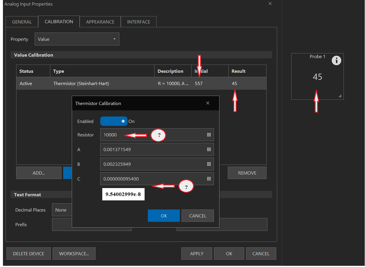
I added a Device Element Analog Input on Port 100
Probe placed in 86 Degree water
Probe reads 557 on Brucontrol
TF3a.png


With these it reads 45.

What is Resistor Value? 10, 000?
Do I use the same coefficients as with the BCS?
What about c? In the BCS you can add scientific notation
 
What is Resistor Value? 10, 000?
Do I use the same coefficients as with the BCS?
What about c? In the BCS you can add scientific notation

Your TF3 board should have included information as to the values of each resistor on the board. You can verify yourself with a multimeter if you have one.Those will be your input resistances. Note there are slight variances for each resistor from 10K ohms, not sure how much that affects the final outcome, I used the supplied info and it was accurate.
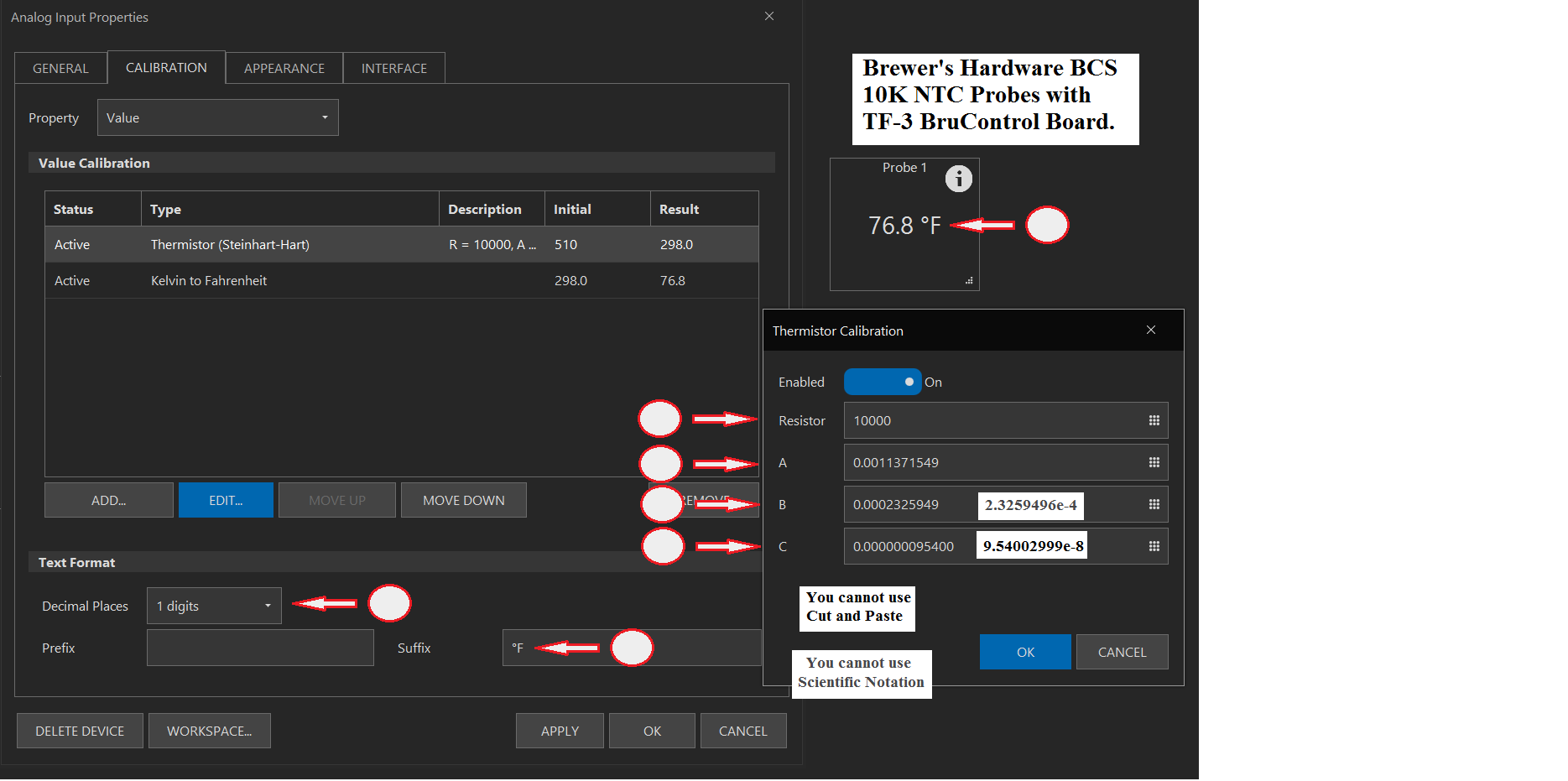
The probe vale of 557 is in degrees Kelvin, you need to add an additional calibration through the pull down menu "Kelvin to Fahrenheit" to get to degrees F. A further Fahrenheit to Celcius is required for degrees C .
Thanks. I guess I have to figure out how to read "resistors" Hard for me. So I need 2 calibrations (if I like Fahrenheit):
1. The Resistor Value and the Coefficents.
Are the ones from BCS good?
2. Kevin to Fahrenheit

I wish there had been better instructions as I cannot find that paperwork. I did not think important when I got the TF3. I have a multimeter but will have to sort out reading resistance.

Resistance readings are fairly simple. Set the dial on your multi meter to 20K ohms and measure across R1 R2 etc to obtain the individual readings. Watch the reading as it will increase towards 10K ohms and stabilize after a few seconds. It may be a bit under or over but use the final reading as your input resistance for that particular resistor. For coefficients I purchased my BCS probes from Brewers Hardware and they have those readings on their site. Otherwise if you purchased elsewhere you will have to refer to the manufacturers specs for those numbers.

Info as per Brewers Hardware
BCS-460 Sensors:
Since these are thermistor-based temperature sensors, there is no polarity to the sensor itself. The black and red wires are used. The unshielded drain wire is in contact with the temperature probe end but is not electrically tied to ground. Binding this wire to your system ground can help reduce interference when running spark igniters or if the wires run near your pumps.

For M8 Quick Disconnect Cables the black and blue wires are used.

You will need to enter the following coefficients into the BCS-460 setup panel to get them to read properly:

A= 0.001137155
B= 2.3259496e-4
C= 9.540003e-8
 
Your B coefficient needs another 0 if you are using the Brewer's Hardware sensors... should be .0002xxxxx (your screenshot shows .002xxx), everything else looked ok.
 
Per @tartan, you should have received a sheet with the actual resistor values with the TF-3. If not, you can measure them yourself. If not, just use 10000.

The coefficients must be entered correctly. Do not use scientific notation. Write the coefficients into notepad or other text editor, then cut and paste those values into BC as those fields may limit how many decimal places you can enter (sorry about that). Once the calibration is set up you should get a temp in Kelvin. Add another calibration to get to Fahrenheit.

Per above you were getting 45, not 557. 45 is not correct, so it looks like your coefficients are not entered correctly.
 
I’m upgrading my valves to motorized ball valves instead of solenoids with a flyback diode. The ball valves are cr03. Should I use a flyback diode again?
 

Attachments

  • ED67C4C9-0D4E-45D1-8616-723625C77E0C.jpeg
    ED67C4C9-0D4E-45D1-8616-723625C77E0C.jpeg
    489.8 KB · Views: 35
Last edited:
I suppose you could put 2 reverse biased diodes: open terminal to ground and close to ground. I don’t think you need these but they won’t hurt.

Edit: only if using DC. If using AC power, skip.
 
Last edited:
If I am reading the resistors right they are 10k. Mutlimeter was 99.

Color code is brown red black black brown so a 10 k.

I used the coefficients that came from the BCS.
Your B coefficient needs another 0 if you are using the Brewer's Hardware sensors... should be .0002xxxxx (your screenshot shows .002xxx), everything else looked ok.
Thanks,
That was the error!
 
Yes, resistors are 10k. They are that value to match the thermistor nominals of 10k. You may not be able to read the resistors in the board accurately is wired in.

Glad you have it working. I’m a thermistor fan!

FYI:
I could not cut and paste the numbers in the a.b.c fields. It would have been and issue with C as that is listed in Scientific Notation on the BCS Interface even if you could Cut and Paste. Would be nicer if you could Cut and Paste and also accept Scientific Notation as well. Also searched this thread and the BruControl forum and that was of little aid. I do want to thank all that responded as it was very frustrating as I did not know where quite to start.

Like most things in BruControl, it was simple once you knew how to hold your mouth and twist your ear. Here is a screen shot of my setup for a Brewer's Hardware BCS Probe.
BCS Probes.png
 
FYI:
I could not cut and paste the numbers in the a.b.c fields. It would have been and issue with C as that is listed in Scientific Notation on the BCS Interface even if you could Cut and Paste. Would be nicer if you could Cut and Paste and also accept Scientific Notation as well. Also searched this thread and the BruControl forum and that was of little aid. I do want to thank all that responded as it was very frustrating as I did not know where quite to start.

Like most things in BruControl, it was simple once you knew how to hold your mouth and twist your ear. Here is a screen shot of my setup for a Brewer's Hardware BCS Probe.

In future you can transcribe the whole expanded coefficients from scientific notation to "Notepad" first then copy and paste from there to the your "Thermistor Calibration" window. This allows you to capture to whole string without rounding off at the end. How much of an effect this has on the accuracy of the final result is probably minimal but it will be the whole coefficient. Manually entering the "C" coefficient in the drop down will not allow you to enter the last few numbers.
You can then copy and paste from Notepad to set up your other temp probes.
 
Last edited:
@Tartan1 has it correct. The User Manual shows an example of coefficients in the thermistor calibration but I admit we must be clearer about scientific notation and decimal entry. The fields do limit entry and we can try to fix that in the future. For now, cut and paste without scientific notation.
 
@Tartan1 has it correct. The User Manual shows an example of coefficients in the thermistor calibration but I admit we must be clearer about scientific notation and decimal entry. The fields do limit entry and we can try to fix that in the future. For now, cut and paste without scientific notation.
I did try to cut and paste. I cut from the BCS Interface and copied to Word. I did go to the internet and got the C Coefficient translated to a decimal and copied and pasted that to Word. I then tried to copy to BruControl. I also copied to Notepad ++ and then recopied. I can cut and paste with abandon except in the A B and C fields. I am using Windows 8.1, but for some reason those fields would not let me paste. I have copied and pasted elsewhere in BruControl without any issues. But not here.
 
FYI, you cannot copy those fields either (CTRL+C). And I did notice that CTRL+ALT+V shortcut (Paste Special) does not seem to work in BruControl for any field. I have used Word to copy Text because I am a terrible speller and let Word help me. This is the only issue that I have run into using Cut and Paste. Even using straight notepad it is a no go. Would be nice that have that Clone feature for any Device Element.
 
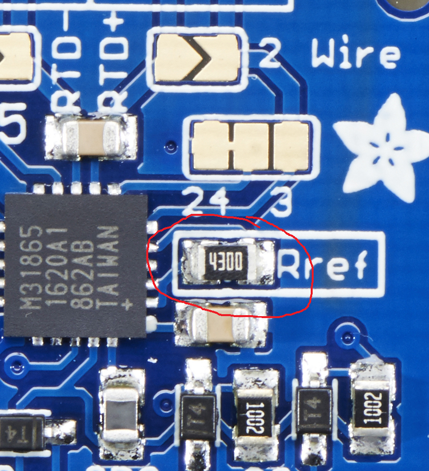
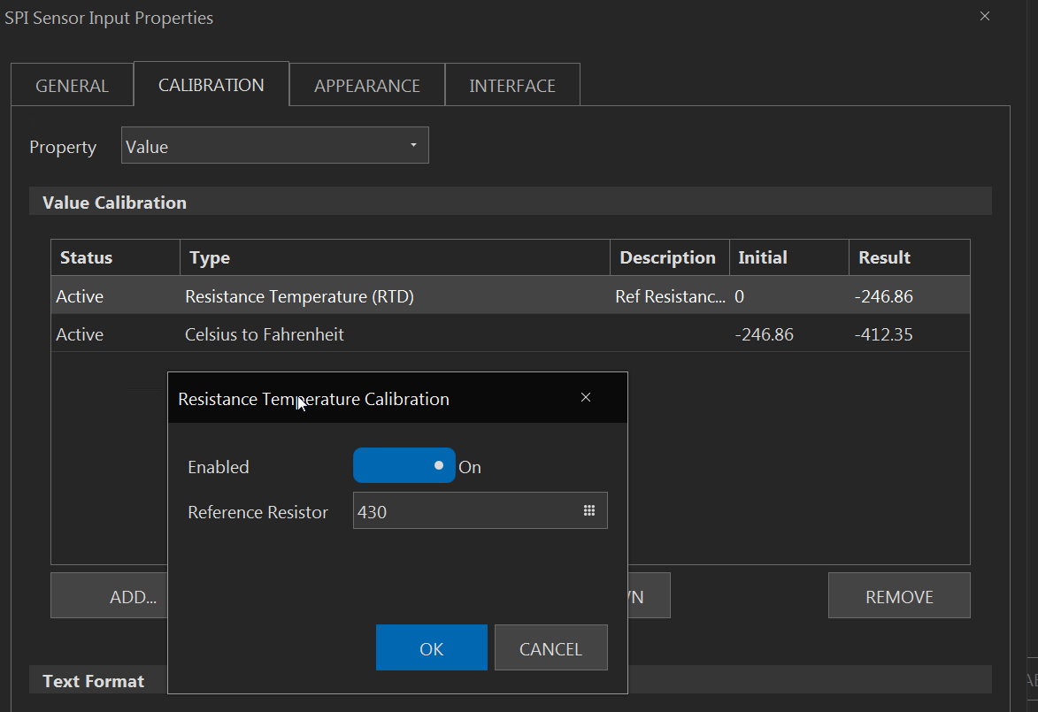
When using an RTD Probe with the SPI RTD Platform RP-3 Board, the CALIBRATION calls for a Reference Resistor: In the schematic it says:

- Note pad resistor for entry into BruControl RTD calibration.

I do not see any resistor on the SPI RTD Platform RP-3 Board. Does this come from the maker of the Probe? I have Aubrins PT100 probes. I looked and did not see any listing for a pad resistor (or any resistor) in the Specs on their site.

Where do I find that Reference Resistor value?
 
I now know that I made an error by soldering these the way I did. I have ordered more amps. I assume that when installed on the RT3 board, the resistor can be read?
 
If I set my Mash BCS Type Probe to read Fahrenheit and the build a Lookup table for Temperatures between 146 °F and 157 °F in one degree increments, will the probe read correctly when outside of the array range I want my mash to be corrected more precise.

I would have the precise Temperatures from a NFC Thermometer.
I Know in my setup, I use the rtd boards with the "430" resistors and found the value does sometimes need to be tweaked to get them to read correctly, (from memory I believe I had set one at like 429.5 or something to that effect. I never had to solder these in either of my panels, just the required solder jumper/bridges to set them up correctly.


Some of this is the variance between rtds I think but we are talking like 1-2 degrees offset that needs to be adjusted against a thermometer to get them all spot on and uniform. every rtd may read slightly different which is why the offset is there.. doesnt matter were you buy them they are all pretty much from the same 2 manufacturers from what I gather. Most like the $12 ebay/amazon ones and the ones auberins resells are DTC brand and they very often will be off from each other a degree or two until calibrated with the offset. in reality its a moot point if these probes are off by one degree as far as how it will effect their purpose here.
 
Last edited:
I would add 1:1 entries at very low and very high points to make sure the interpolation outside the mash range is correct.

For example:
0:0
150:150
151:151.2
152:152.3
153:153.3
154:154.2
155:155.1
156:156.1
157:157
250:250

Result numbers are hypotheoretical here.
 
If I have time I will do an experiment to see once I get the wiring done. On the BCS, I had a Cheat Sheet Lookup table. If it was off 1.4 degrees, I would just set the Target to that Offset. I prefer this Lookup table correction. It was always confusing when I was Mashing at 154.0 but the Target Temps read 155.4.
 
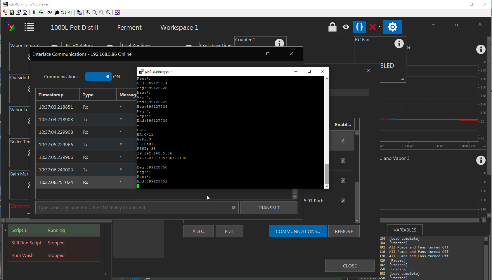
Simple process to use a Rpi ZeroW UART to monitor serial debug over the network.

*note - This is for 3.3V items only, such as SP8285/8286 of the SonOff devices. Mega2650 is 5V!

Step 1 - Set up the Pi (working RPi ZeroW running Buster and having wifi set up)
#ssh to the Pi ( I used Putty )
#enable UART
sudo sed -i -e "\$a\enable_uart=1" /boot/config.txt
#stop boot commands from goign to serial port:
sudo sed -i.bak 's/console=serial0,115200 //' /boot/cmdline.txt
#install screen program:
sudo apt install screen
sudo reboot

sudo screen /dev/ttyS0 115200

#use "ctrl a d" to disconnect

Step 2 - Physically connect the devices:
Rpi(pin) - SonOff
Gnd(6) - Gnd
TXD(8) - Tx
RXD(10) - Rx *optional

Step 3 - Turn on Debug:
In BruControl:
Settings --> Interfaces --> <interface> --> Communications
Send the following string: %1
To stop, send: %2

upload_2019-8-3_10-42-35.png
 
Really nice write-up! Thanks for sharing.

In your case I hope it exposes something. My bet is it is a power supply issue as is the case with 99% of microcontroller failures. This might not expose it but I hope we learn something from it.
 
Back
Top