BruControl: Brewery control & automation software

Homebrew Talk - Beer, Wine, Mead, & Cider Brewing Discussion Forum

Help Support Homebrew Talk - Beer, Wine, Mead, & Cider Brewing Discussion Forum:

This site may earn a commission from merchant affiliate links, including eBay, Amazon, and others.
Don’t confuse static IP with router assigned IP’s. Your router will only assign an IP address (based on the MAC) if the client (BruControl interface in this circumstance) requests one using DHCP.

If the interface does request one, the router can assign it either from it’s available IP “pool” or range of IPs designated in its settings. The risk of this is the router can assign different IPs each time the request is issued. This would obviously cause a communication disconnect with BC. Alternatively, (and this is mentioned above and recommended), the router can assign a specific IP to the requesting interface based upon the interface’s MAC address. This is typically called an IP reservation, and is the best of all worlds since it will ensure the interface always has the same IP and will prevent duplicate IPs getting used on the network, per below.

If the interface is self assigning a static IP (not using DHCP), then it doesn’t care what the rest of the network thinks, including the router. It’s going to use that IP, which risks duplicate IPs on the network of the admin (that’s you) isn’t super careful to keep the static IPs aligned to just one device and out of the pool used by the router’s DHCP.

Again, once you either pick a MAC or use the one on the label, don’t change using that one. If you change it, or the IP used with it, I’d suggest restarting the BC computer to flush out the MAC <-> IP table in its network controller.

As @clearwaterbrewer mentioned, use a debug code to have the interface report its IP address. Next step is to ping it to make sure it is communicating. If it does, then you can connect with BC.
 
I am trying to connect a Mega (Robodyn) 2560 using Ethernet.

I used the setup.bat (v45) to configure the Mega for a MAC and IP Address. The Only question I had was DCHP which I set to "N" (I assumed because I was setting a Static IP.)

I added the Interface and used the following:View attachment 637347

I manually added the device to my Frontier FIOS Router and it got the MAC Address from the Mega but Ping Tests or BruControl Communications do not work.

Any ideas?

Did you handle the enable jumper (I can’t recall if it was solder it closed or remove the solder jumper. Someone who knows weigh in please!
 
My Router would not allow me to create a second Static with the same IP. I deleted the Static IPs before I did another on my router. I have yet to get one to connect. Right now I only have one Static IP for a Mega on the Router. I can always start fresh in the morning with a New MAC Address and new IP.

That may work because the ARP entry (maps the MAC to IP in memory) will have timed out.
 
Did you handle the enable jumper (I can’t recall if it was solder it closed or remove the solder jumper. Someone who knows weigh in please!

It is to remove the solder jumper on the back or alternatively jumper 3.3VDC pin to PIN #7 (RobotDyn MEGA) Just be sure not to assign PIN 7 as an output or you will short the connection.
 
Last edited:
My Router would not allow me to create a second Static with the same IP. I deleted the Static IPs before I did another on my router. I have yet to get one to connect. Right now I only have one Static IP for a Mega on the Router. I can always start fresh in the morning with a New MAC Address and new IP.

1 - Try setting a [DHCP Reservation in your router] for your laptop or some other device to make sure you have the setup correct.
2 - Remember that unplugging the ethernet will clear the ARP(MAC-IP translation) from the devices on each end of the cable, but not a third device in the network, such as your PC, that may need a few minutes or a manual clearing to time out.

Here is a short display of a win10 MAC Address table and how to clear a single entry or all... don't worry, it is automatically re-filled, so clearing it does not hurt it.
Code:
Microsoft Windows [Version 10.0.16299.666]
(c) 2017 Microsoft Corporation. All rights reserved.

C:\windows\system32>arp -a

Interface: 192.168.2.124 --- 0x4
  Internet Address      Physical Address      Type
  192.168.2.1           e0-5f-b9-77-be-9c     dynamic
  192.168.2.51          d4-6a-6a-ec-ea-b8     dynamic
  192.168.2.101         50-3d-e5-a1-dd-84     dynamic
  192.168.2.114         68-ec-c5-25-fe-ea     dynamic
  192.168.2.115         20-25-64-7d-3f-3c     dynamic
  192.168.2.119         78-0c-b8-4f-f7-04     dynamic
  224.0.0.22            01-00-5e-00-00-16     static
  224.0.0.251           01-00-5e-00-00-fb     static
  239.255.255.250       01-00-5e-7f-ff-fa     static

C:\windows\system32>arp -d 192.168.2.119

C:\windows\system32>arp -a

Interface: 192.168.2.124 --- 0x4
  Internet Address      Physical Address      Type
  192.168.2.1           e0-5f-b9-77-be-9c     dynamic
  192.168.2.51          d4-6a-6a-ec-ea-b8     dynamic
  192.168.2.101         50-3d-e5-a1-dd-84     dynamic
  192.168.2.114         68-ec-c5-25-fe-ea     dynamic
  192.168.2.115         20-25-64-7d-3f-3c     dynamic
  224.0.0.22            01-00-5e-00-00-16     static
  224.0.0.251           01-00-5e-00-00-fb     static
  239.255.255.250       01-00-5e-7f-ff-fa     static

C:\windows\system32>arp -d *

C:\windows\system32>arp -a

Interface: 192.168.2.124 --- 0x4
  Internet Address      Physical Address      Type
  192.168.2.1           e0-5f-b9-77-be-9c     dynamic

C:\windows\system32>
 
Last edited:
1 - Try setting a [DHCP Reservation in your router] for your laptop or ....
I had used the arp -a command and had not seen the 192.168.1.160 or the 192.168.1.159 which were the two static IPs I had set up (before I set them up). I jumpered the 3.3v to pin 7 and that did not seem to fix the issue. Using arp -a, I do not see either now, but if I use the Router Interface, they are both there and say "Active". Cannot ping them either.
 
OK, I used a different Mega and had that set up as 192.168.1.159 and had cleared my router of the two static IPs. I jumpered 3.3v to PIN 7. Added to BruControl (without reserving on my Router), and it connected immediately. Maybe it was a bad Mega I was using in addition to not knowing about the Jumper. There are a few Solder Jumpers on the Back of the Robodyn Mega. One is labeled D7. Is that the jumper I remove? I would prefer that than losing PIN 7. I might try that on the bad? Mega.
 
I had used the arp -a command and had not seen the 192.168.1.160 or the 192.168.1.159 which were the two static IPs I had set up (before I set them up). I jumpered the 3.3v to pin 7 and that did not seem to fix the issue. Using arp -a, I do not see either now, but if I use the Router Interface, they are both there and say "Active". Cannot ping them either.

make sure they are not in a DMZ or something on the router, what is the router model?
 
Here is my issue I have been running into, wireless 'SonOff Dual' interfaces using the ESP8285 are regularly disconnecting after running for a few days... If I power cycle the interface, it runs fine for a few days...

Remote full reset would be really nice...


Don’t put much credence in BC actually connecting saying when its flashing like that. BC sees the device but is not actually communicating when this happens. What does the communications dialogue show?

I am perplexed why it works for hours then stops without successfully reconnecting. It should never need to be reset. Admittedly we don’t have a lot of experience with the Sonoffs but it is a basic 8285. Usually the underlying power supply is to blame with microcontroller failures - I wonder if that is failing at some point? That can probably only be seen by a scope to look at the noise. Can you repeat this with a debug window running?
 
OK... I will look next time they are disconnected...

I have purchased 2 batches of these from iTead.cc, the first time I bought 2, and the 2nd time I bought 4, they are different board revisions, 1.0 and 1.4.. I know that #6 that was bouncing is a 1.0 board and the #1 unit is a 1.4 board. 2-3 others work fine (they have flow counters, not temp probes) I *think* I put v.45 firmware on every one of them and I think they had had the same issue with 43 or 44....

Next step like you say is to get a unit to fail when next to my desktop and put the serial adapter on it.. I have moved the #6 unit next to my PC...
 
Last edited:
make sure they are not in a DMZ or something on the router, what is the router model?
They are not in the DMZ (disabled regardless) and I removed them from the Static IP Reservation. I have an older Toshiba with 1ghz AMD E -21 chip and 4 gb of Ram along with a powered USB Hub with through power as well that I am thinking about hooking up and just going serial and using remote desktop.
 
OK... I will look next time they are disconnected...

I have purchased 2 batches of these from iTead.cc, the first time I bought 2, and the 2nd time I bought 4, they are different board revisions, 1.0 and 1.4.. I know that #6 that was bouncing is a 1.0 board and the #1 unit is a 1.4 board. 2-3 others work fine (they have flow counters, not temp probes) I *think* I put v.45 firmware on every one of them and I think they had had the same issue with 43 or 44....

Next step like you say is to get a unit to fail when next to my desktop and put the serial adapter on it.. I have moved the #6 unit next to my PC...

We initially found and proposed the Sonoff as an option, but in truth I’m hesitant to think some of these have anything approaching industrial level quality. We’re always conflicted between approachable cost of purchase and reliability. To me, if it’s not reliable, it’s not worth any cost, including free!

My personal refrigeration controller has been the model of what reliability should look like for a BC system (and I’m not saying this to gloat, but as an expectation we have for our users). It is a Feather M0 with a Li-Po battery, powered by a small 5V switching supply, reading two thermistors, driving two freezers via a 2-channel relay board, and feeding a local LCD display. It has run continually without a hiccup for 3+ years straight, surviving the heat, power flashes and lightning typical of south FL summers. It honestly rarely, if ever, disconnects, but I have commercial grade access point and I’m sure the battery has been a big help but too.

Anyway, since you run a commercial operation, we need to get your stuff reliable. I might come visit sometime I’m up near Tampa!
 
I would say the Best and Bane of BruControl is hardware. It is not easy to figure out the Hardware as there are no "standards". I am not an Micro computer guru. The fact that there are no "standards" make it difficult for non gurus. A good example is the Ethernet with the Mega. I have 3 different ones and can only get one to work. I bought 3 different power supplies (12v) then bought 3 more switching (also 12v) only to find out in the Homebrewtalk that 12v is too much. Some Standards would be nice. I have yet to wire up from my BCS because I have had Hardware issues regarding the Mega 2560. In addition, you new screw shield looks great. Finally one that you can play nice with the screw shield and an Ethernet shield.

I would love to see some Hardware standards that work out of the box with instructions. I know that this is an evolving plan, but would be nice to the rest of us to settle.
 
This is fair feedback. We have had every intention of providing an opportunity to be flexible - the other side of that freedom see-saw lots of opportunities for combinations that don’t play well.

I would argue your MEGA problem is solvable and that 12V is not necessarily too much depending on how it’s being used. We’ve built lots of Ethernet shield based units and rarely have them not work at the start. We are happy to help you through it via email or even phone as long you can help us understand what parts you are using, how it’s being put together etc.
I am sure most of the issue is because I do not understand the world of micro computers.

Regarding the 12v power supply. In this forum some users said that is too much for long term use. I normally leave mine powered on at all times because of fermentation. Is that OK or do I need to do the battery solution suggested in some previous posts in this thread.

The screw shield issue where you cannot stack is so simple to fix but no one had done so. When I go to micro forums, that is an issue for all users, not just BruControl. And the issue with PIN 7 to 3.3v. That is left field stuff for me. Is that only on the Robodyn or on all Mega 2560? Can I de solder the D7 on the back of the Robodyn and gain back my Pin 7? I had planned on using Pin 7.
 
12V used on any Arduino sporting the typical 3 terminal linear regulator just leads to excessive thermal dissipation and a shortened life span. As awkward as it might be in environments like a BC system where 12V is handier, 9V is the better choice, with 1A switching wall warts available for a couple of bucks...

Cheers!
 
De Solder D7 is correct!

See Post #1666 and I did it. It does work. I did buy the Adafruit battery. I was using Wall Warts for the Mega and have a bigger 12v and 24 v DC power supply as well as a 5v Buck transformer for any widget power. I know see the Mega I could not get working. So I have two Mega with Ethernet. Now to start wiring.
 
@day_tripper is correct. 9V is a happy middle. Using 12V however is possible but may be also dependent on how much current you look to pull through the regulator. A Wi-Fi shield and multiple active high outputs will tax it more. The enclosure and cooling would make a difference too.

Regarding the D7 / RST jumper on that integrated Ethernet MEGA, it is a bit counter-intuitive. Despite the silkscreen saying "disconnected" is the default - it is soldered closed. Not sure whasup there.

Also, for more flavor what is happening here is the jumper holds the Ethernet in a reset state, so it is basically off. Tying D7 to 3.3V turns the Ethernet on, but also applied 3.3V to Pin 7, so if you told D7 to be an active low output, it would essentially short that pin, risking damaging that output (and probably more than that). We could turn the Ethernet on/off via Pin 7 in firmware, but we don't do that for the shields, so felt no reason to make custom firmware for this board.
 
Last edited:
I may have missed it in one of the earlier posts but what's new in FW 45C?

Since the main 45 release, it includes some minor increments, including the pull-up resistor mistake (Active Low inputs), a repeating checksum error for serial connections (introduced in 45B), Grand Central support, and the *option* to enable higher resolution analog-digital conversion for analog inputs for boards which support it. We'll roll the actual implementation out soon, but it requires changes to the interface definition files, so we need to write that up carefully.

So, not much beyond 45 to be honest. I wouldn't update unless you are using active low inputs and/or are already using 45B.
 
@day_tripper is correct. 9V is a happy middle...

Regarding the D7 / RST jumper on that integrated Ethernet MEGA, it is a bit counter-intuitive. Despite the silkscreen saying "disconnected" is the default - it is soldered closed.
...
We could turn the Ethernet on/off via Pin 7 in firmware, but we don't do that for the shields, so felt no reason to make custom firmware for this board.

Not quite sure I totally understand. If I desolder D7 on the back of the board (which I did) and have my Ethernet connected from the Robotdyn Mega to my network, does that still mean I lose Pin #7 since it seems tied to the Ethernet? My Plan was to use it as a Digital Out to control a 110 vac SSR for a Plate Igniter (7 seconds On). I have two Igniters now controlled by one BCS Output. I can leave it wired that way as it has worked for years and just use one Port/Pin on the Mega.
 
Howdy everyone,

Just thought I would drop a tip in case this hasn't been posted yet.
I've been waiting for the ability to mirror my BruControl system on a remote machine and finally found a great solution for my use case which was access without having to purchase Windows 10 Pro to enable RDP, or use of VNC.

Features:
- shared clipboard
Allows for remote editing of the brucontrol scripts
- displays in web browser directly

If you setup 'remotedesktop.google.com' on your BruControl system you can mirror the machine to anything with a web browser capable of rendering Google's Remote Desktop interface. One downside is that it doesn't seem to allow for more than one session at a time.

Travis
 
Not quite sure I totally understand. If I desolder D7 on the back of the board (which I did) and have my Ethernet connected from the Robotdyn Mega to my network, does that still mean I lose Pin #7 since it seems tied to the Ethernet? My Plan was to use it as a Digital Out to control a 110 vac SSR for a Plate Igniter (7 seconds On). I have two Igniters now controlled by one BCS Output. I can leave it wired that way as it has worked for years and just use one Port/Pin on the Mega.

The RST side of the jumper needs 3.3V (or 5V) in order for Ethernet to be enabled. With the jumper soldered (as it comes from the factory), that ties the RST line to D7. If the firmware wanted to turn on/off Ethernet, it could do that by setting D7 to a high output (5V). Since BC firmware does not do that, you would need to force it high with a jumper tying 3.3V (or 5V) to D7. No problem if D7 is left off (high impedance) or turned high (active high ON). Big problem if D7 is turned low (active low ON) as it would short the pin out.

If you remove the jumper, Ethernet is enabled full time and you can do what you want with D7 as it will not be tied to anything else.

If soldering (de-soldering, that is) isn’t your bag, then you could [very] carefully grind off the solder ball with a dremel tool. Otherwise, tie pin 7 to 3.3V (or 5V) and never use Port 7 in BC. With ~45 I/O that a MEGA format offers, it should be easy to use another pin (unless if you are @Die_Beerery!)

Make sense?
 
As I review the dual element 50 amp schematic as a starting place for my build, I have a few questions. As I said before, I am not a ee, but have done a fair amount of house wiring, put computers together from scratch and done soldering.

Are VCC and VIN the same thing?


V symbol.jpg

Is this symbol just an indication of voltage on the line or does this represent some component to be installed?


50A DP 120V Coil.jpg

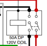
These look like relays. Are they contactors (not sure the difference) and what exactly do I purchase? Also how to they get activated since I don't see anything attached to the Arduino? Are they automatically on with power applied?


BrunDog Control Panel 01.jpg

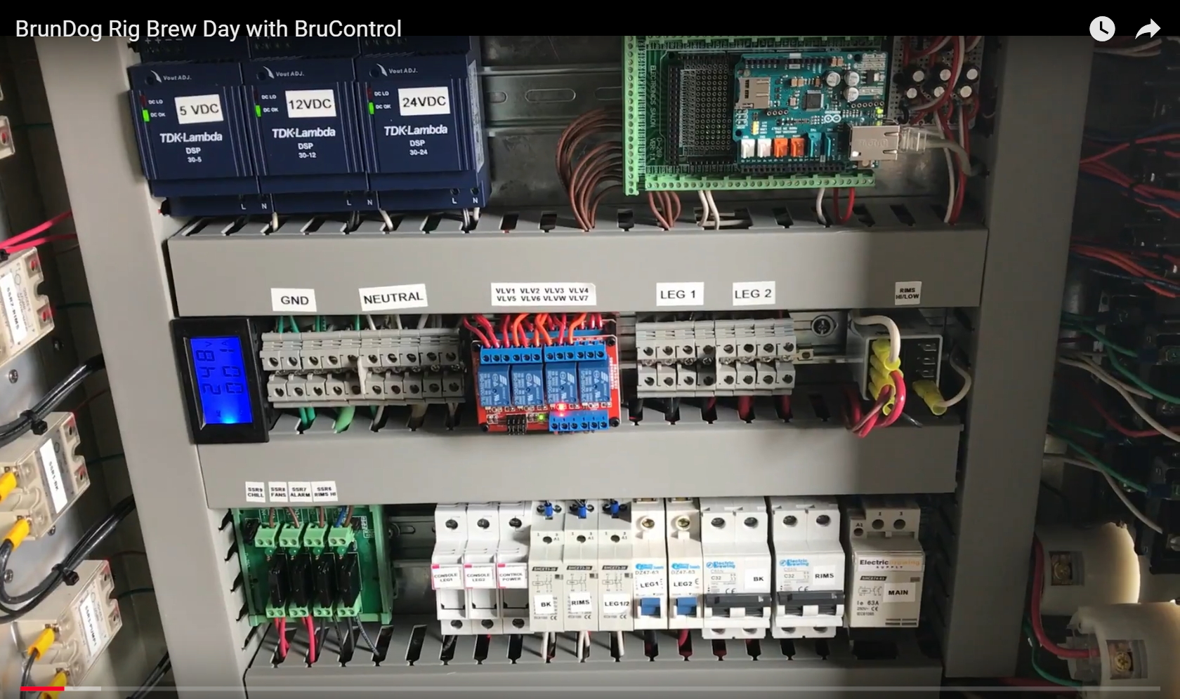
Also, where are these in this pic of brundogs panel?


Brundog Panel 01.jpg

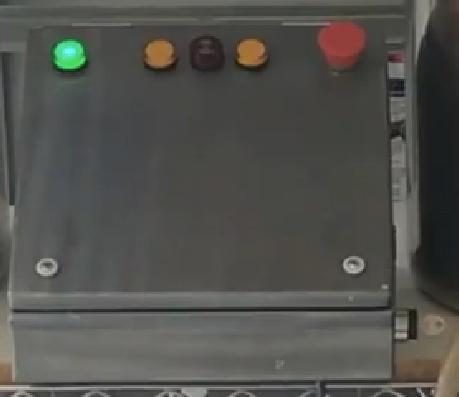
Brundogs panel: Am assuming that red is e-stop, green is power, ambers are the elements. Is the black in the middle a fuse?

Also, can someone recommend a program to use to lay out my own schematic?
 
Are VCC and VIN the same thing?


v-symbol-jpg.637893

Is this symbol just an indication of voltage on the line or does this represent some component to be installed?


50a-dp-120v-coil-jpg.637895

These look like relays. Are they contactors (not sure the difference) and what exactly do I purchase? Also how to they get activated since I don't see anything attached to the Arduino? Are they automatically on with power applied


v-symbol-jpg.637893
Indicates an inline fuse 1A ea


50a-dp-120v-coil-jpg.637895
Indicates 50A Double Pole Contactor with a 120VAC coil


In the photo the relays are in the center ( red block of 4) and the contactor is bottom right (63A) and the fuses could be on the door panel or under the wire track. I use Draw.io as it was simpler to use Brundog's schematics and modify as required. PM him and he can send you a editable schematic.
 
Last edited:
Thanks. I got a de-solder plunger and some braid and it is very easy to do. I have practiced using a solder iron to do some through the hole stuff and some xlr connectors before. I put the iron on and clicked the plunger. De-soldered! I cleaned up with the braid. Did it the first time I tried. Now just making sure that the Pin Outs on the screw shield are correct. Maybe start wiring in this week.
 
On the TF3: The schematic shows the 5 vdc tied to the AREF (on the Mega) and VCC on the TF3. Does the 5v need to be from the Mega 2560 because it is used connected to the AREF Pin? I have a Buck Transformer from 24vdc to 5vdc that I planned on using to power any other pieces of hardware that need 5+ vdc rather than the pin off the Mega.
 
As I review the dual element 50 amp schematic as a starting place for my build, I have a few questions. As I said before, I am not a ee, but have done a fair amount of house wiring, put computers together from scratch and done soldering....

I'd highly recommend The Complete Guide to Building Your Electric Brewery if you've never built an industrial control/power box before. I used it to build the controls for a 3V 1bbl consecutive batch (almost 300amp) nano-brewery a few years ago. We've since moved on to a slightly more expensive system, but it worked well as we were poor and scaling. Now we are just poor ;)

The book/pdf will explain a lot of stuff you'll likely never consider if you haven't built one before...and especially if you aren't familiar with industrial control systems! There are likely other resources available to learn all of that stuff, but since I haven't been paying attention in the past four or five years this is the only one I know to recommend.
 
I am perplexed why it works for hours then stops without successfully reconnecting. It should never need to be reset. Admittedly we don’t have a lot of experience with the Sonoffs but it is a basic 8285. Usually the underlying power supply is to blame with microcontroller failures - I wonder if that is failing at some point? That can probably only be seen by a scope to look at the noise. Can you repeat this with a debug window running?

Still waiting for it to fail again, wondering how I set up termite on a *powered* SonOff via the CH340. Without power to the SonOff, I use the guide you have which has the Gnd/Tx/Rx/Vcc and then tying button0 to ground..

I tried just Gnd/Rx/Tx, with and without button 0, and then I also tried with Vcc... I can program an unplugged SonOff just fine.. well, I used to be able to, maybe I fried the CH340... both SonOffs on my desk I tried it with still work fine... time to order a couple more CH340's...

Thinking the easy way may be to put a RPi zeroW next to it and use pins 6(Gnd), 8(Txd), and 10(Rxd) on the Pi to go to Gnd, Rx, and Tx on the SonOff? both are 3.3V logic level right? Then basically look at https://www.raspberrypi.org/documentation/configuration/uart.md to enable and use /dev/serial0
 
We initially found and proposed the Sonoff as an option, but in truth I’m hesitant to think some of these have anything approaching industrial level quality. We’re always conflicted between approachable cost of purchase and reliability. To me, if it’s not reliable, it’s not worth any cost, including free!

My personal refrigeration controller has been the model of what reliability should look like for a BC system (and I’m not saying this to gloat, but as an expectation we have for our users). It is a Feather M0 with a Li-Po battery, powered by a small 5V switching supply, reading two thermistors, driving two freezers via a 2-channel relay board, and feeding a local LCD display. It has run continually without a hiccup for 3+ years straight, surviving the heat, power flashes and lightning typical of south FL summers. It honestly rarely, if ever, disconnects, but I have commercial grade access point and I’m sure the battery has been a big help but too.

Anyway, since you run a commercial operation, we need to get your stuff reliable. I might come visit sometime I’m up near Tampa!

Would love a visit, bring a spare liver, I have 20 spirits and we have 7 really good craft breweries in a 1.1 mile walking loop... yes, SEVEN.. it went from being called 'the Beermuda Triangle' to 'the Gauntlet'...

My feather M0 died after being in a project box for less than a week :-( It takes a program, but other than that it is dead... will probably try the ESP32 feather huzza thing for the battery, but the $5 ESP32's work great too...

The package is just so nice... built in power and HV connections in a case for less than $10... the only one I messed up, I fried the GPIO 5 on... if SonOff makes a Dual with a ESP32(just for OTA) and more GPIO's available as thru-holes for pins to be soldered to, I would have 20 of em! (I have sent a request and they said they would 'look at it'...)
 
Howdy everyone,

Just thought I would drop a tip in case this hasn't been posted yet.
I've been waiting for the ability to mirror my BruControl system on a remote machine and finally found a great solution for my use case which was access without having to purchase Windows 10 Pro to enable RDP, or use of VNC.

Features:
- shared clipboard
Allows for remote editing of the brucontrol scripts
- displays in web browser directly

If you setup 'remotedesktop.google.com' on your BruControl system you can mirror the machine to anything with a web browser capable of rendering Google's Remote Desktop interface. One downside is that it doesn't seem to allow for more than one session at a time.

Travis

Good tips Travis. I have used this with success. People can also check our TeamViewer. It will mirror to any device and I believe it does allow simultaneous sessions.
 
On the TF3: The schematic shows the 5 vdc tied to the AREF (on the Mega) and VCC on the TF3. Does the 5v need to be from the Mega 2560 because it is used connected to the AREF Pin? I have a Buck Transformer from 24vdc to 5vdc that I planned on using to power any other pieces of hardware that need 5+ vdc rather than the pin off the Mega.

Check out https://brucontrol.com/wp-content/u...trol-Thermistor-with-TF-3-board-Schematic.pdf. You can use the 5V from the buck as long as the grounds is tied together with the MEGA. I would use the MEGA 5V though as thermistor circuits draw very little current.
 
Still waiting for it to fail again, wondering how I set up termite on a *powered* SonOff via the CH340. Without power to the SonOff, I use the guide you have which has the Gnd/Tx/Rx/Vcc and then tying button0 to ground..

I tried just Gnd/Rx/Tx, with and without button 0, and then I also tried with Vcc... I can program an unplugged SonOff just fine.. well, I used to be able to, maybe I fried the CH340... both SonOffs on my desk I tried it with still work fine... time to order a couple more CH340's...

Thinking the easy way may be to put a RPi zeroW next to it and use pins 6(Gnd), 8(Txd), and 10(Rxd) on the Pi to go to Gnd, Rx, and Tx on the SonOff? both are 3.3V logic level right? Then basically look at https://www.raspberrypi.org/documentation/configuration/uart.md to enable and use /dev/serial0

If you can just leave a terminal attached and let it run, you will be much more likely to catch an issue. Use debug level 1.
 
Would love a visit, bring a spare liver, I have 20 spirits and we have 7 really good craft breweries in a 1.1 mile walking loop... yes, SEVEN.. it went from being called 'the Beermuda Triangle' to 'the Gauntlet'...

My feather M0 died after being in a project box for less than a week :-( It takes a program, but other than that it is dead... will probably try the ESP32 feather huzza thing for the battery, but the $5 ESP32's work great too...

The package is just so nice... built in power and HV connections in a case for less than $10... the only one I messed up, I fried the GPIO 5 on... if SonOff makes a Dual with a ESP32(just for OTA) and more GPIO's available as thru-holes for pins to be soldered to, I would have 20 of em! (I have sent a request and they said they would 'look at it'...)

Not sure I have that kind of tolerance... Sonoff Package is nice indeed, but you are a grown boy so its time to use big-boy toys!
 
Not sure I have that kind of tolerance... Sonoff Package is nice indeed, but you are a grown boy so its time to use big-boy toys!

I remember when a local brewery got a quote for $90,000 to replace 12 1/16DIN fermenter temp controls with a system that would allow internet monitoring and touchscreen display... I showed him my BCS, and they said I should have seen the look on the Siemens rep's face...
 
If you can just leave a terminal attached and let it run, you will be much more likely to catch an issue. Use debug level 1.

That is what I was trying to do.... but the interface does not take commands from the CH340 while connected to BC... but I got it working:

To debug on a live, powered interface:
Connect the CH340 Gnd and Rx to the interfaces Gnd, and Tx respectively. (yes, just 2 wires)
Go to BC --> Settings --> <interface> --> communications and type %1 <enter>
To stop, send a %2

Now, to be able to do this remotely, the ones on my desk are not failing.... thinking RPi zeroW that logs to a rolling log file...
 
Last edited:
Back
Top