Another Electric Panel Build

Homebrew Talk - Beer, Wine, Mead, & Cider Brewing Discussion Forum

Help Support Homebrew Talk - Beer, Wine, Mead, & Cider Brewing Discussion Forum:

This site may earn a commission from merchant affiliate links, including eBay, Amazon, and others.

Eaglesbrewer44

Active Member
Joined
Jan 3, 2022
Messages
29
Reaction score
7
Location
Little north of Philly
Hello all, I'm new to the forum and I'm seeking feedback on my 220v Electric Brew Panel. I'm not an expert in building electric panels(this is my first attempt), but I feel fairly confident after studying other builds on this forum and other popular electric build sites. That being said, before I plug anything in and flip the switch, I want to socialize my design to be sure I did not design this panel ass backwards.

Here are some features I wanted on this 220v panel:
  • The ability to turn off/on the element while the panel is plugged in
  • Run a water pump
  • Run a Blichmann 4000 watt Boil coil
  • Be as safe as I can be with electric
Here are the components I plan on using:
  • 11x8x4 project box
  • 25 amp SSR
  • 25 amp external heat sink
  • 25 amp breaker for on/off switch
  • Auber's 30 amp din rail terminal set
  • A ground terminal
  • A 5 amp fuse terminal
  • 32 amp rated contactor
  • 30 amp double pole single throw switches(I should have bought simple toggle switches, but I think these will still work)
  • 18, 14, & 10 gauge wire where need based on the amperage
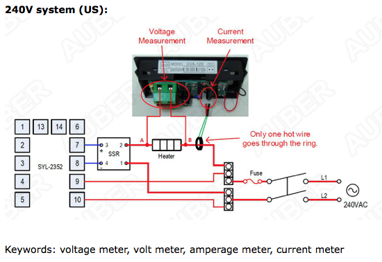
  • 2352 PID
  • Volt and amp meter
  • Power coming from 30 amp Siemen GFCI breaker

As you will see in the attached diagram, I went with the Din Rail approach and split the wires to the PID with a 5 amp fuse terminal. After reading this section's Electric Primer for Brewers Sticky today, now I'm wondering if need to add a 15 amp breaker for the 120v pump outlet. Anyhoo, I would appreciate any feedback. Thanks in advance!
 

Attachments

  • 20220106 Panel wiring 220v v1.jpg
    20220106 Panel wiring 220v v1.jpg
    123.9 KB · Views: 86
Last edited:
I am not an expert either, but I have built a few panels. One thing I would suggest is going with a higher rated SSR (and related items). While you are fine with using a 25 amp that for the 4k watt boil coil, if you stepped up to a 40 amp version, you would be able to use your panel for the full extent of your 30 amp panel. It would have more flexibility for the future. Also, I would add power indicator lights on the pump and element. I am upgrading my newest panel with that next weekend after I accidentally almost dry fired my element while cleaning up from my last brew day. They are cheap and provide a nice visual. Another thing I would add is a fan. I have put one in every panel I have built with the idea that it hopefully is extending the life of the SSR and keeping the PID in its working temp specs.
 
Thanks for the feedback! One thing I'll add is I'm building 2 panels, one 25 amp 220v panel to power the 4k watt boil coil and another 20 amp panel to power a 120v boil coil. My thinking was to simplify each panel instead of trying to build one panel to run everything. Also, I thought I could make the 20 amp 120 panel portable if I ever wanted to brew inside.(I plan on brewing in my garage) I hear you on the 25 amp SSR, but I'm fine with building another panel in the future if I need to expand.

As for the power indicator, I bought switches that light up when the components are on. My thinking was to simplify the panel face and wiring inside the panel. I could add more light indicators if it makes sense. It was an important safety feature for me to be able to turn off and know the element is off while the panel is plugged in.

As for the fan, I have a 25 amp external heat sink. Do you think this is sufficient? One of the reason I went with this 25 amp heat sink and 25 Amp SSR is because it fit my small project box. I'll add I already bought everything, but It's not a big deal to go a different direction if it makes sense. Thanks JJinMD!
 
That all makes sense. Thanks for the idea of lighted switches... that might alter my weekend plans.

On the fan, I just think (this is a IMHO type of thing) that with a panel, while the heat sink is cooling the SSR, where is the heat actually going from there in your panel box? A cheap 220v fan seems like good insurance, so I put one on my panels. You can even mount them externally, so they don't take up any room in your box. On my last one, I put it on the topside instead of the face of the panel. If I was to put one on your design, I would do the same because then it is right by the SSR sucking the heated air out.


Would you have a picture of this external fan? So you're saying you would put a fan in the box even if the heatsink is mount externally? Here is a picture of my panel mocked up for reference.
 

Attachments

  • IMG_0454.jpg
    IMG_0454.jpg
    715.4 KB · Views: 70
OK, I see how you did it. With that design, I guess you wouldn't need the fan since all the heat should go through the heatsink. I could take a picture, but basically on my box, the fan is exactly where your heat sink is! I hadn't really thought about doing it that way. Neat!
 
Yes, you should put a fuse for the pump in where the wire size changes from 10AWG to 14AWG. A 10 A fuse is adequate, but 15 A is ok for the 14AWG wiring.

Brew on :mug:
 
Yes, you should put a fuse for the pump in where the wire size changes from 10AWG to 14AWG. A 10 A fuse is adequate, but 15 A is ok for the 14AWG wiring.

Brew on :mug:
Would you recommend 10a breaker instead or just go with a fuse terminal? I would imagine I need a 10a fuse or breaker for both the neutral and hot line. Thanks!
 
Would you recommend 10a breaker instead or just go with a fuse terminal? I would imagine I need a 10a fuse or breaker for both the neutral and hot line. Thanks!
Either one works equally well. You only need to fuse hot lines. You don't have to fuse neutrals, as they cannot source current (they don't have to be switched for the same reason.) You never, ever fuse or switch ground lines.

Brew on :mug:
 
+1 on upgrade the SSR and the matching heatsink. It is good to over rate silicon and hard to have excessive heat management. The additional cost does not add that much more to the total cost of the project.
 
Theres minimal cost difference between a 25a SSR and a 40a SSR. When talking electrical, sizing up is always a good idea. In theory, higher load capacity = lower heat output, prob not in practice tho, but still, go for 40a and be done with it.

Internal fan isnt needed so long as you have an external heat sink. The inside of my panel never gets that hot, but the heatsink certainly does, so its doing its job. An external fan blowing over the heat sink is obviously not going to do anything but help keep temps down, but its not overly necessary. I was worried for a while of temps across my heat sink, and had a small DC fan jury rigged to blow air across it, but ended up ditching it and i havent had a problem, even after bumping up my wattage on my element. Just made sure to get a good connection between the heat sink and the SSR with some thermal paste.
 
Alright, the forum has spoken;) I'll upgrade to a 40 SSR and bigger heatsink. I'll also update my panel on/off breaker to a 30 amp breaker. Might as well use the full power of the 30 Main breaker. Thanks all for the input!
 
I received my 32a breaker, 40a SSR, and larger heat sink and made a little more progress over the weekend. I switched everything out and started to wire the components.

Question
I got to my voltmeter and I'm not sure if I'm following the wiring diagram correctly. I'm using' Auber's 2 in 1 voltmeter ammeter gauge that measures both volts and amps. Based on the attached diagram, Can in just wire in the voltage measurement to the SSR using 18 gauge wire and run the current measurement (ring) wire to the outgoing black wire? I just want to make sure it's ok to run lighter gauge wire right off the SSR.
 

Attachments

  • control panel wiring.jpg
    control panel wiring.jpg
    2.5 MB · Views: 55
  • control panel upgraded heatsink.jpg
    control panel upgraded heatsink.jpg
    745.3 KB · Views: 54
  • Screen Shot 2022-01-09 at 6.17.14 PM.png
    Screen Shot 2022-01-09 at 6.17.14 PM.png
    157.4 KB · Views: 50
I received my 32a breaker, 40a SSR, and larger heat sink and made a little more progress over the weekend. I switched everything out and started to wire the components.

Question
I got to my voltmeter and I'm not sure if I'm following the wiring diagram correctly. I'm using' Auber's 2 in 1 voltmeter ammeter gauge that measures both volts and amps. Based on the attached diagram, Can in just wire in the voltage measurement to the SSR using 18 gauge wire and run the current measurement (ring) wire to the outgoing black wire? I just want to make sure it's ok to run lighter gauge wire right off the SSR.
The meter draws very little current, so 18AWG wire is fine. You could fuse the wires to the meter (both voltage connections) if you want to protect against potential shorts of the 18AWG wire to something else.

Brew on :mug:
 
Tonight I realized I may have bought the wrong contactor(at least for my original wire diagram) for my 220 panel. As you might have read, I'm building a 120v panel and a 220 panel. While purchasing my components list, I bought a 32a 120v contactor and a 32a 220v contactor. In my infinite wisdom, I thought that number was rating for the voltage output, but I now know after reading the installation diagram, the voltage rating is for the voltage control. My original plan was to grab the voltage control wire from the 5a terminal and a neutral wire. Now, I think I need 2 hot leads for the 220v voltage control on my 32a contactor. Attached are contactor wiring diagrams for the 120v and 220v contactor. Let me know if attachment 2 would work for the 220 contactor or should I just go ahead and order a 120v 32a contactor for my 220v panel build. For my 220 approach, I would just tap off the red wire before the contactor.
 

Attachments

  • wiringv 120v control.jpg
    wiringv 120v control.jpg
    129 KB · Views: 32
  • wiringv 220v control.jpg
    wiringv 220v control.jpg
    128.9 KB · Views: 30
Can't tell from your drawings how the coils of the contactors wired. However, your text description appears to be correct.

Brew on :mug:
 
Today was my big test run and ran into an issue. I plugged my panel in and flipped the main power switch. The PID powered up. I then flipped the switch to the element. I expected the volt meter to power on and instead I heard a fairly loud hum. I powered the box off and unplugged it immediately. I dismounted the panel and took a look at my wiring again. Based on my knowledge, which probably is not saying much, everything look correct from a wiring standpoint. The PID turned on, so that tells me I have power going to that correctly. I did not get an error with my temp probe so that also installed correctly. Something is going on starting with my 32a Contactor and possibly SSR wiring. My first thought is the orientation of my Contactor. I have the L1 and L2 power in going into terminals 2 and 4 of the Contactor. On the other side of the Contactor, I have Terminal 1, my black wire, going to my SSR output number 1. The SSR output number 2 goes to my element.Terminal 3, my red wire, goes straight to my element. Maybe the Contactor needs to be reversed?

Im stumped.
 

Attachments

  • 40E3B769-2966-4817-A09F-04129B3EC935.jpeg
    40E3B769-2966-4817-A09F-04129B3EC935.jpeg
    1.8 MB · Views: 39
The contactor in vs. out shouldn't matter. A pic of the door component wiring would help.

Brew on :mug:
 
The switch to the left of the PID powers the Contactor. The bottom of the switch is fed from my 5a terminal fuse. The outgoing wire goes to connection A1 on the Contactor. The A2 connection on the Contactor has a neutral connection from the din rail neural terminal.

The wires at the top of the volt meter connect to output 2 on the SSR. This wire has a 1a inline fuse. The other wire on the volt meter connects to the volt ring.

Thanks for taking a look for me!
 

Attachments

  • CA0F0710-A0BF-4AF8-A400-33AA0E959F3B.jpeg
    CA0F0710-A0BF-4AF8-A400-33AA0E959F3B.jpeg
    3.6 MB · Views: 45
Maybe I just have a bad SSR? The humming starts the instant I turn on the element power.
The SSR shouldn't hum - there's really no way for it to do so. Contactors can hum if the voltage to the coil is lower than the rated voltage. Your contactor says it has a 110-120V coil, but there is a small possibility of a manufacturing mistake.

The power inputs to your Volt/Amp meter are incorrect. The jumper shouldn't be there. You need to have both L1& L2 connected to the green terminal on the V/A meter.

Brew on :mug:
I updated my voltmeter wiring based on your feedback. This wiring makes sense now. I was a little confused with the instruction diagram.

I checked all my connections again and still cannot get power after the contactor. The PID and the 120 outlet work correctly. When flip on the element switch I get the same hum at the contactor. I took the cover off and noticed the light did not come on the contactor either. The volt meter did not turn on. I'm not sure what else I can troubleshoot at this point. Maybe the best thing to do here is just order another contactor and see if replacing it solves the issue.
 

Attachments

  • panel open.jpg
    panel open.jpg
    2.7 MB · Views: 34
I think your plan is sound. If your contactor is mislabeled as 110V coil, but actually has a 220V coil, that would explain the symptoms (humming but no voltage on output side.) You should be able to hear the contactor click when you turn on the controlling switch.

Brew on :mug:
 
Double check the contactor coil rating. Make sure it is rated for the correct voltage that it is XXX Volts AC. (not XXX volts DC)

I do not see the coil of the contactor on your schematics. You might have it wired such that the coil shuts itself off and then back on kind of a thing.

Try dis connecting the contactor coil and run some jumpers from an bewitched power source (of an appropriate voltage) and see if it buzzes under that condition.

ETA: Looking at your schematic, you are using black 10 gauge red wire for Leg 1 and 14 gauge black for Leg 2. Why the mix? Not saying it will not work, but typically you match wire size Leg 1 and Leg 2.
 
Last edited:
Double check the contactor coil rating. Make sure it is rated for the correct voltage that it is XXX Volts AC. (not XXX volts DC)

I do not see the coil of the contactor on your schematics. You might have it wired such that the coil shuts itself off and then back on kind of a thing.

Try dis connecting the contactor coil and run some jumpers from an bewitched power source (of an appropriate voltage) and see if it buzzes under that condition.

ETA: Looking at your schematic, you are using black 10 gauge red wire for Leg 1 and 14 gauge black for Leg 2. Why the mix? Not saying it will not work, but typically you match wire size Leg 1 and Leg 2.
39)

I have the 32a 110v coil and from the description and it should be AC current.

I'm running 10 gauge for Leg 1 and Leg 2. The Red wire in the contactor comes directly from the main power switch and the Black wire comes from the main hot terminal. My initial drawing has changed a bit, so we both might be referring to a different wire. I'm 99.9% sure all the gauge wire is consistent and correct based on voltage and amperage.

I'm not sure if there is another way to wire the contactor. Here is how I have it wired:

Contactor power in
Main Power L1(Black) -> Din Hot Terminal -> contactor terminal 2
Main Power L2(Red) -> contactor terminal 4

Contactor power out
Power L1(Black) -> contactor terminal 1-> SSR -> power cable
Power L2(Red) -> contactor terminal 3 ->power cable

Power to 110v Coil
Hot Terminal wire(14g) -> DPST switch "O" side(Only using one side of switch)
DPST "I" side -> Coil A1
Main Terminal neutral -> Coil A2

I'll try your idea of jumping the coil with a hot wire right from the terminal.

Thanks!

Let me frank. The fact there you tell me you have a 32 amp 110v coil tells me you are in trouble. There is no way the coil of that contactor is 32 amps. That coil is probably around 0.100 amps. The contacts are what are 32 amps. The coil and the contacts of a contactor/relay are electrically independent of each other.

When it comes to contactor/relay coil, the two specs you have to get right is the voltage (5 volts, 12 volts, 48 volts, 110 volts, etc) and the type AC or DC. If you do not match the current source spec and coil spec you are in trouble, like buzzing relays.

Your schematic does not show the contactor coil. I cannot follow the text description in your reply.

I wrote a user guide for a relay board a few years ago. Most if what is in here does not apply to your build. Maybe the first fee pages will be if some help.

https://www.homebrewtalk.com/threads/sainsmart-relay-board-user-guide.523263/
 
I just jumped the contactor directly from the hot and neutral terminals and had the same buzzing issue. This is becoming a bit frustrating.

Then the relay is bad/defective/mislabeled or the vendor got you the wring part of you ordered the wring part.

Can you post a close up of the relay itself? The part with the specs printed on the relay?
 
Let me frank. The fact there you tell me you have a 32 amp 110v coil tells me you are in trouble. There is no way the coil of that contactor is 32 amps. That coil is probably around 0.100 amps. The contacts are what are 32 amps. The coil and the contacts of a contactor/relay are electrically independent of each other.

When it comes to contactor/relay coil, the two specs you have to get right is the voltage (5 volts, 12 volts, 48 volts, 110 volts, etc) and the type AC or DC. If you do not match the current source spec and coil spec you are in trouble, like buzzing relays.

Your schematic does not show the contactor coil. I cannot follow the text description in your reply.

I wrote a user guide for a relay board a few years ago. Most if what is in here does not apply to your build. Maybe the first fee pages will be if some help.

https://www.homebrewtalk.com/threads/sainsmart-relay-board-user-guide.523263/

From my understanding I have a 110v coil. 32 amps is what I understand the contactor(relay) to be rated at. I thought I could describe is as a 32a 110v coil, but I now know that's not how you describe a contactor and a coil.

I guess I am missing something in my design if I'm not showing a contactor coil. I thought the Contactor and coil is illustrated directly on the din rail

I posted my build here to share my build learn from people who have done this before. I researched and planned as best I could so please bear with me if this is a stupid question...If my coil in my contactor is rated for 110v, shouldn't I be able to power it on with one hot leg of the 220v power cable and a neutral wire? Isn't that 110v?
 
Last edited:
I wonder if I'm getting 220v from my main 100a sub panel. I had an 100a sub panel installed in my garage and have 30 amp gfci breaker and outlet installed for my brew panel. I had an electrical install the panel and outlet so and I'm fairly certain these items are installed correctly. I have other outlets besides my brew panel that run off this 100a sub panel and the outlets work just fine.

If my PID powers up when I flip the main power on the brew panel and my 120 volt outlet on the bottom of my brew panel can power on/off a test light, do you think I confidently rule out that I have my 100a sub panel and 30a outlet installed incorrectly?
 
Last edited:
From my understanding I have a 110v coil. 32 amps is what I understand the contactor(relay) to be rated at. I thought I could describe is as a 32a 110v coil, but I now know that's not how you describe a contactor and a coil.

I guess I am missing something in my design if I'm not showing a contactor coil. I thought the Contactor and coil is illustrated directly on the din rail

I posted my build here to share my build learn from people who have done this before. I researched and planned as best I could so please bear with me if this is a stupid question...If my coil in my contactor is rated for 110v, shouldn't I be able to power it on with one hot leg of the 220v power cable and a neutral wire? Isn't that 110v?
If it were my panel, this is what I would do.

Disconnect the wires from terminals 1 thru 4. This is not supposed to make a difference, but who knows. All you are looking at is the coil circuit. Pull the wires off and put electrical tape and cover the exposed copper

Yes, from one of the two legs of your 220v to the neutral (not ground) will give 110v. This matches the rated voltage of the coil. If you apply terminal A1 to one of your two 220v legs , then A2 to Neutral, the relay should click/snap once and be very quiet.

You need to trouble shoot this before going take the next step.

You can put a switch inline between the voltage source and A1. When you turn the switch to on, you should hear the contactor click once. Turn off the switch, another click.

Once you have this working, you can wire up 220v on terminals 1 thru 4.

FINALLY, SUCCESS!!!

So here is what I did. I removed the hot lines going into the contactor while it was hard wired from the hot and neutral terminals. I turned it on. It buzzed for a second and then clicked. I then unplugged it, wired my switch again and BAM, it worked! Turns out I had everything wired correctly, but it seems like the contactor was just stuck or something. Anyone experienced this before?

4B02A00C-275C-435C-9E1F-D0F3D01FBBE9.jpeg


Thanks RufusBrewer and Doug293cz for helping me troubleshoot this.
 
Back
Top