You are using an out of date browser. It may not display this or other websites correctly.
You should upgrade or use an alternative browser.
You should upgrade or use an alternative browser.

Help Support Homebrew Talk:
This site may earn a commission from merchant affiliate
links, including eBay, Amazon, and others.
That will turn both elements on at the same time. Assuming your home gets 230, each element will draw ~14A, for a total of 28A.
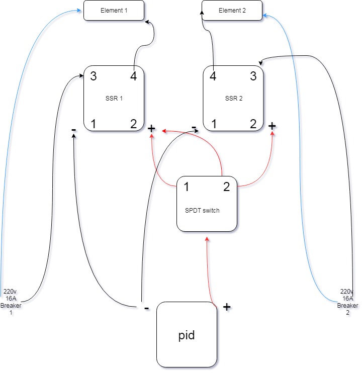
If you want to control one element at a time, connect the (-) of the pid to both SSRs, then use a SPDT switch to select which SSR gets the (+).
postalbunny
Well-Known Member
I went a different route... dual elements, and i just ran the power plug from the SSR to each outlet. Eg, through contactor to each "x" leg on the plug, then through the SSR to each "y" leg. That way the SSR toggles the 240v leg for both elements in unison. No reason to have two SSR's unless you're trying to fire two elements at different times.
Thanks for reply 
I agree that both elements are not always needed.
And have the ability to turn them on and off individually.
So here is my plan nr 2
If I turn switch on 1 then element 1 will be ON and when I turn the switch to 2 will both be ON?
Bought me an Auber EZboil, so I'm terrified of ruining something here: P
PS: I have contactors available but haven't added them here..

No reason to have two SSR's unless you're trying to fire two elements at different times.
Even if i need to use 2 fuses (16A)?

$53.24
1pc Hose Barb/MFL 1.5" Tri Clamp to Ball Lock Post Liquid Gas Homebrew Kegging Fermentation Parts Brewer Hardware SUS304(Gas MFL)
Guangshui Weilu You Trading Co., Ltd

$49.95 ($0.08 / Fl Oz)
$52.99 ($0.08 / Fl Oz)
Brewer's Best - 1073 - Home Brew Beer Ingredient Kit (5 gallon), (Blueberry Honey Ale) Golden
Amazon.com

$76.92 ($2,179.04 / Ounce)
Brewing accessories 1.5" Tri Clamp to Ball Lock Post Liquid Gas Homebrew Kegging Fermentation Parts Brewer Hardware SUS304 Brewing accessories(Gas Hose Barb)
chuhanhandianzishangwu

$58.16
HUIZHUGS Brewing Equipment Keg Ball Lock Faucet 30cm Reinforced Silicone Hose Secondary Fermentation Homebrew Kegging Brewing Equipment
xiangshuizhenzhanglingfengshop

$53.24
1pc Hose Barb/MFL 1.5" Tri Clamp to Ball Lock Post Liquid Gas Homebrew Kegging Fermentation Parts Brewer Hardware SUS304(Liquid Hose Barb)
yunchengshiyanhuqucuichendianzishangwuyouxiangongsi

$176.97
1pc Commercial Keg Manifold 2" Tri Clamp,Ball Lock Tapping Head,Pressure Gauge/Adjustable PRV for Kegging,Fermentation Control
hanhanbaihuoxiaoshoudian
![Craft A Brew - Safale S-04 Dry Yeast - Fermentis - English Ale Dry Yeast - For English and American Ales and Hard Apple Ciders - Ingredients for Home Brewing - Beer Making Supplies - [1 Pack]](https://m.media-amazon.com/images/I/41fVGNh6JfL._SL500_.jpg)
$6.95 ($17.38 / Ounce)
$7.47 ($18.68 / Ounce)
Craft A Brew - Safale S-04 Dry Yeast - Fermentis - English Ale Dry Yeast - For English and American Ales and Hard Apple Ciders - Ingredients for Home Brewing - Beer Making Supplies - [1 Pack]
Hobby Homebrew

$7.79 ($7.79 / Count)
Craft A Brew - LalBrew Voss™ - Kveik Ale Yeast - For Craft Lagers - Ingredients for Home Brewing - Beer Making Supplies - (1 Pack)
Craft a Brew

$22.00 ($623.23 / Ounce)
AMZLMPKNTW Ball Lock Sample Faucet 30cm Reinforced Silicone Hose Secondary Fermentation Homebrew Kegging joyful
无为中南商贸有限公司

$44.99
$49.95
Craft A Brew - Mead Making Kit – Reusable Make Your Own Mead Kit – Yields 1 Gallon of Mead
Craft a Brew

$479.00
$559.00
EdgeStar KC1000SS Craft Brew Kegerator for 1/6 Barrel and Cornelius Kegs
Amazon.com

$20.94
$29.99
The Brew Your Own Big Book of Clone Recipes: Featuring 300 Homebrew Recipes from Your Favorite Breweries
Amazon.com

$33.99 ($17.00 / Count)
$41.99 ($21.00 / Count)
2 Pack 1 Gallon Large Fermentation Jars with 3 Airlocks and 2 SCREW Lids(100% Airtight Heavy Duty Lid w Silicone) - Wide Mouth Glass Jars w Scale Mark - Pickle Jars for Sauerkraut, Sourdough Starter
Qianfenie Direct

$719.00
$799.00
EdgeStar KC2000TWIN Full Size Dual Tap Kegerator & Draft Beer Dispenser - Black
Amazon.com
Yes, that will be the end result if you connect them that way.If I turn switch on 1 then element 1 will be ON and when I turn the switch to 2 will both be ON?
Or you must use two separate 16A circuits that cannot be connected to a single SSR...No reason to have two SSR's unless you're trying to fire two elements at different times.
What size of brewing are you doing? 5 gallon 10 gallon? A single 3200watt may be more than enough? Just curious.
At this time the fermenting volume is 15 gallon.
And i do a 2 vessel brewing (loop) so i heat all the water at onse (20 gallon).
The heating time between each mesh steps or when its boiltime is to long now.
Last edited:
postalbunny
Well-Known Member
Or you must use two separate 16A circuits that cannot be connected to a single SSR...
I'd advise against anyone trying to run multiple circuits into a single enclosure... just seems like a bad idea unless you really know what you're doing. Even if it's a rented apartment and you're trying to make due with limited electrical... If Franknh is doing 15gallon batches he should probably at least use the dryer outlet for 30amps. Grab an "RV Extension cable" and run it to your brew area and you'll have 30 or 50 amps at your disposal. This will also allow you to go 240v without trying to combine two circuits in your house off different service legs. 240v will allow more wattage at less amps.
Thanks for reply.I'd advise against anyone trying to run multiple circuits into a single enclosure... just seems like a bad idea unless you really know what you're doing. Even if it's a rented apartment and you're trying to make due with limited electrical... If Franknh is doing 15gallon batches he should probably at least use the dryer outlet for 30amps. Grab an "RV Extension cable" and run it to your brew area and you'll have 30 or 50 amps at your disposal. This will also allow you to go 240v without trying to combine two circuits in your house off different service legs. 240v will allow more wattage at less amps.
Yes i know, but i only got 16A in my house. Beside the 25A for the stove.
Not that I have no respect for electricity, but 2 sircuits into the brewery panel as long as you keep them separate is ok.
The cabinet is designed with 2 circuits where each feeds 1 element and 1 pump.
augiedoggy
Well-Known Member
As long at the wiring is totally isolated your fine. My 3bbl panel runs off of two 60a gfci protected circuits.
If you use two separate circuits, then you need to keep the neutrals separate as well as the hots. If you don't, the GFCI's, or equivalent in your country, will be tripping all the time.
Brew on
Brew on

If you use two separate circuits, then you need to keep the neutrals separate as well as the hots. If you don't, the GFCI's, or equivalent in your country, will be tripping all the time.
Brew on
I was asking in another forum about merge 2 pcs 16A as one 32A but that was no-go
So i will totally seperate these sircuits.
Frank
This circuit will not work the way it is intended. Both elements will be enabled (i.e. "on") for both switch positions. Trace the connectivity in the two states, and you will see why. If you can't figure it out, ask and I will walk you thru it.Thanks for reply
I agree that both elements are not always needed.
And have the ability to turn them on and off individually.
So here is my plan nr 2
If I turn switch on 1 then element 1 will be ON and when I turn the switch to 2 will both be ON?
Bought me an Auber EZboil, so I'm terrified of ruining something here: P
PS: I have contactors available but haven't added them here..
View attachment 637155
It can be fixed by adding a second switch block for position 2.
Brew on

This circuit will not work the way it is intended. Both elements will be enabled (i.e. "on") for both switch positions. Trace the connectivity in the two states, and you will see why. If you can't figure it out, ask and I will walk you thru it.
It can be fixed by adding a second switch block for position 2.
Brew on
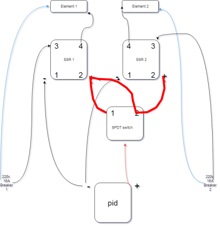
Unless I'm misunderstanding, I think you're wrong here. The SPDT ensures that only one of the SSRs are turned on at a time (floating input on an SSR = off).
When the switch is in position 1, then terminal 1 on the switch (which is hot) connects to terminal 2 on the left SSR. Terminal 2 on the left SSR is also connected to terminal 2 on the switch, so now terminal 2 on the switch becomes hot. Terminal 2 on the switch connects to terminal 2 on the right SSR, so now the right SSR terminal is also hot. The heavy red line shows what is connected to the PID output when the switch is in position 1.Unless I'm misunderstanding, I think you're wrong here. The SPDT ensures that only one of the SSRs are turned on at a time (floating input on an SSR = off).

Brew on

augiedoggy
Well-Known Member
I believe passedpawn is correct here. An SPDT switch allows continuity between the single pole input to either one of the out outputs. So either ssr# or ssr #2 would get the signal from the pid with no selection to kill both or allow both at the same time. It operates like many a/b selector switches would. The diagram here shows what I mean.When the switch is in position 1, then terminal 1 on the switch (which is hot) connects to terminal 2 on the left SSR. Terminal 2 on the left SSR is also connected to terminal 2 on the switch, so now terminal 2 on the switch becomes hot. Terminal 2 on the switch connects to terminal 2 on the right SSR, so now the right SSR terminal is also hot. The heavy red line shows what is connected to the PID output when the switch is in position 1.
View attachment 660117
Brew on
http://www.learningaboutelectronics.com/Articles/What-is-a-single-pole-double-throw-switch-SPDT
When the switch is in position 1, then terminal 1 on the switch (which is hot) connects to terminal 2 on the left SSR. Terminal 2 on the left SSR is also connected to terminal 2 on the switch, so now terminal 2 on the switch becomes hot. Terminal 2 on the switch connects to terminal 2 on the right SSR, so now the right SSR terminal is also hot. The heavy red line shows what is connected to the PID output when the switch is in position 1.
View attachment 660117
Brew on
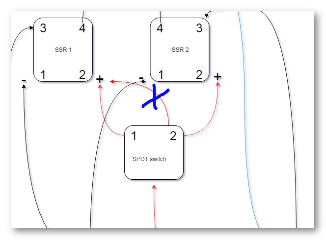
Oh man I had some sort of mental block. I hadn't noticed that connection from SPDT#2 to SSR#1. You were right. Get rid of that connection and it'll work. Though, I'm not certain what the goal of the OP was.
augiedoggy
Well-Known Member
My bad I should have read the whole thread.. I thought Doug drew in the red lines to show current somehow and was really confused.. No arguement from me.. but without the red wires in the diagram the device would work to allow one or the other as long as both ssrs are functioning correctly and not stuck on.
Aha, that's why both elements were turned on whether I had the switch on 1 or 2. I did not see that before 
I had to use 2 switches, 1 for each element.
But if I put a relay between + on SSR1 and Terminal 2 on the switch it would work?
Perhaps there is an easier way to block backfirering of power to the element 2?
I had to use 2 switches, 1 for each element.
But if I put a relay between + on SSR1 and Terminal 2 on the switch it would work?
Perhaps there is an easier way to block backfirering of power to the element 2?
Aha, that's why both elements were turned on whether I had the switch on 1 or 2. I did not see that before
I had to use 2 switches, 1 for each element.
But if I put a relay between + on SSR1 and Terminal 2 on the switch it would work?
Perhaps there is an easier way to block backfirering of power to the element 2?
Assuming it's still like the last diagram you posted, all you have to do is get rid of the one connection (I put an X in it below)

Assuming it's still like the last diagram you posted, all you have to do is get rid of the one connection (I put an X in it below)
View attachment 661125
Sure?
I know I'm not good at explaining, but the thing is, I want 3000W when I use switch 1 and 6000W when I switch to switch 2
With your suggestion, I get:
Switch 1. 3000W from element 1 or
Switch 2. 3000W from element 2
but i want:
Switch 1. 3000W from element 1
Switch 2. 6000W total from element 1 and 2
augiedoggy
Well-Known Member
you need another type of switch... basically you just need one wired permanently without a switch off the pid output and a regular on off switch on the red line to the second ssr...Sure?
I know I'm not good at explaining, but the thing is, I want 3000W when I use switch 1 and 6000W when I switch to switch 2
With your suggestion, I get:
Switch 1. 3000W from element 1 or
Switch 2. 3000W from element 2
but i want:
Switch 1. 3000W from element 1
Switch 2. 6000W total from element 1 and 2
you need another type of switch... basically you just need one wired permanently without a switch off the pid output and a regular on off switch on the red line to the second ssr...
Ahh, smart
Thanks!
Think of wires as pipes. In the drawing, the two wires converge on terminal 2 of the switch and are therefore electrically bonded. There is no switch position that will unbond the positive terminals of the SSR. IOW, both SSRs get the connection no matter where the switch position is.
One solution is to use a DPDT switch. The + from the controller goes to both common legs (1P and 2P). In throw position one 1T is connected to SSR#1 +. 2T goes nowhere. In throw position 2, 1T goes to SSR#1 + and 2T goes to SSR#2 +. Sorry I don't feel like drawing.
Augiedoggy's suggestion also works but if you want one switch to also perform the "all off" function, you would use a DPDT switch as I mentioned but you'd get one with a CENTER OFF.
Scout
Well-Known Member
A single pole double throw switch would be what you want.
augiedoggy
Well-Known Member
Didnt we just go through this? LOL thats NOT what he wants. that would only allow one or the other and not both at once.A single pole double throw switch would be what you want.
What's needed is something like an Auber SW3, with an added NO switch block. This would allow a 1, none, or both selection. Let's say one NO block on the left and two NO blocks on the right. The left block connects to SSR 1, as does one of the right blocks. The other right block connects to SSR 2. The other side of all switches are commoned, and go to the PID.
Brew on
Brew on

augiedoggy
Well-Known Member
I agree or a dual pole on/off/ on switch like bobby mentioned.What's needed is something like an Auber SW3, with an added NO switch block. This would allow a 1, none, or both selection. Let's say one NO block on the left and two NO blocks on the right. The left block connects to SSR 1, as does one of the right blocks. The other right block connects to SSR 2. The other side of all switches are commoned, and go to the PID.
Brew on
Yeah, I was in a hurry when I read Bobby's post, and didn't take time to work thru it. The two are equivalent, but I just leave out the not required pair of contacts.I agree or a dual pole on/off/ on switch like bobby mentioned.
Brew on

Similar threads
- Replies
- 20
- Views
- 771


