As promised here are some more pictures:
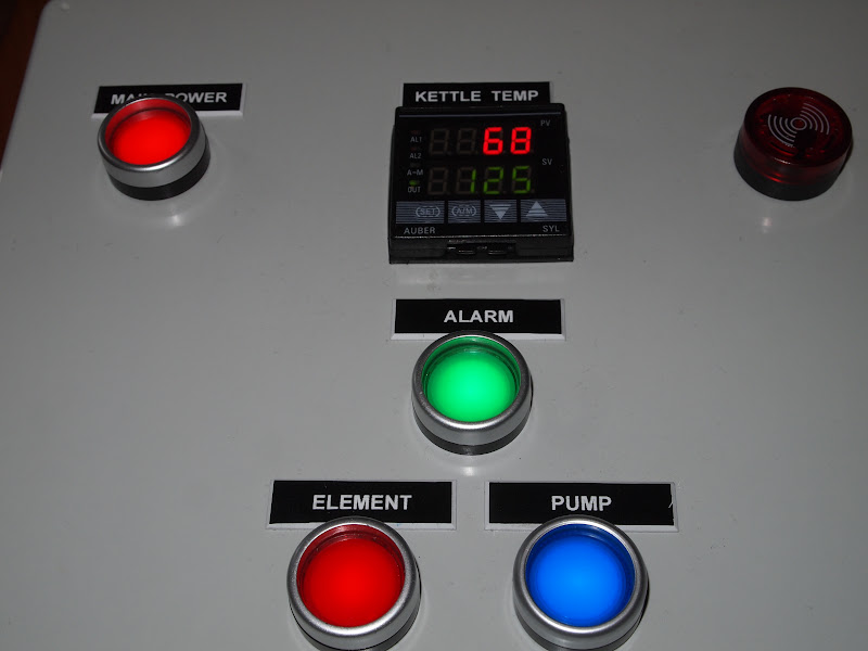
Close up of the front panel with all of the controls lit up.
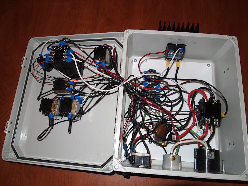
The insides of the control panel. The switches, PID and alarm on the left, the SSR on top, the contractors, terminal strip and outlets on the right.
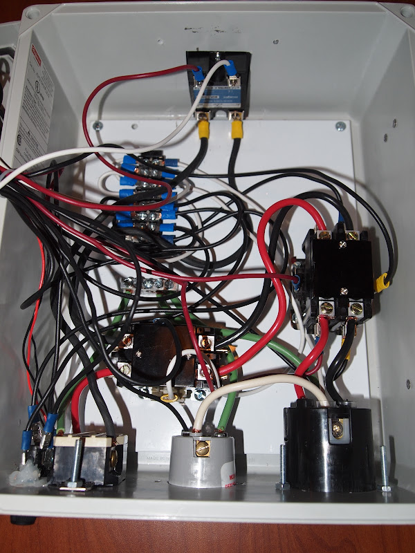
Attached to the top is the SSR (screwed and thermal pasted to the heatsink). In the top left of the subpanel is a terminal strip, which feeds the hot and neutral lines for the 120V stuff. Below that is the ground bus bar that services all the ground runs. It's hard to tell from the photo, but the paint on the subpanel has been sanded off so the bus bar is in direct contact to it, grounding the subpanel (the only metallic part of the panel.) On the far right is the main power contactor. Just above the 120V and 240V outlets is the element power contactor. Also on the bottom left of the photo against the bottom edge you can see my hack job of securing one of the fuses holders with silicone, because I did not measure properly. (Remember measure twice cut, once....

)
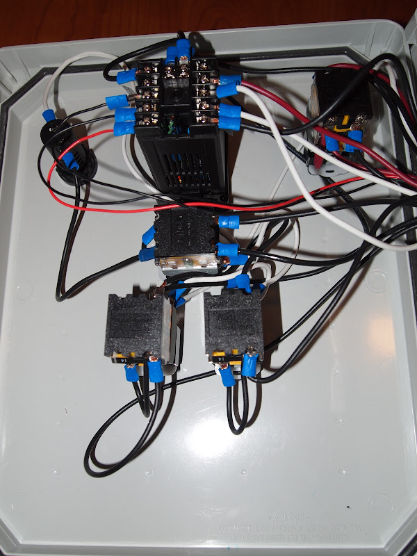
Close up of the backside of the front panel. On the top, from left to right the alarm, PID and main power button. Right below the PID is the alarm button. The bottom row is the pump and element buttons.
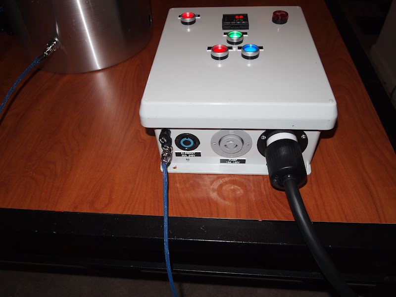
A bottom view showing the power cord coming from the GFCI spa panel (not shown) which is connected to a dryer outlet and the probe going to the kettle RTD sensor.


![Craft A Brew - Safale S-04 Dry Yeast - Fermentis - English Ale Dry Yeast - For English and American Ales and Hard Apple Ciders - Ingredients for Home Brewing - Beer Making Supplies - [1 Pack]](https://m.media-amazon.com/images/I/41fVGNh6JfL._SL500_.jpg)