iSpindle - DIY Electronic Hydrometer

Homebrew Talk - Beer, Wine, Mead, & Cider Brewing Discussion Forum

Help Support Homebrew Talk - Beer, Wine, Mead, & Cider Brewing Discussion Forum:

This site may earn a commission from merchant affiliate links, including eBay, Amazon, and others.
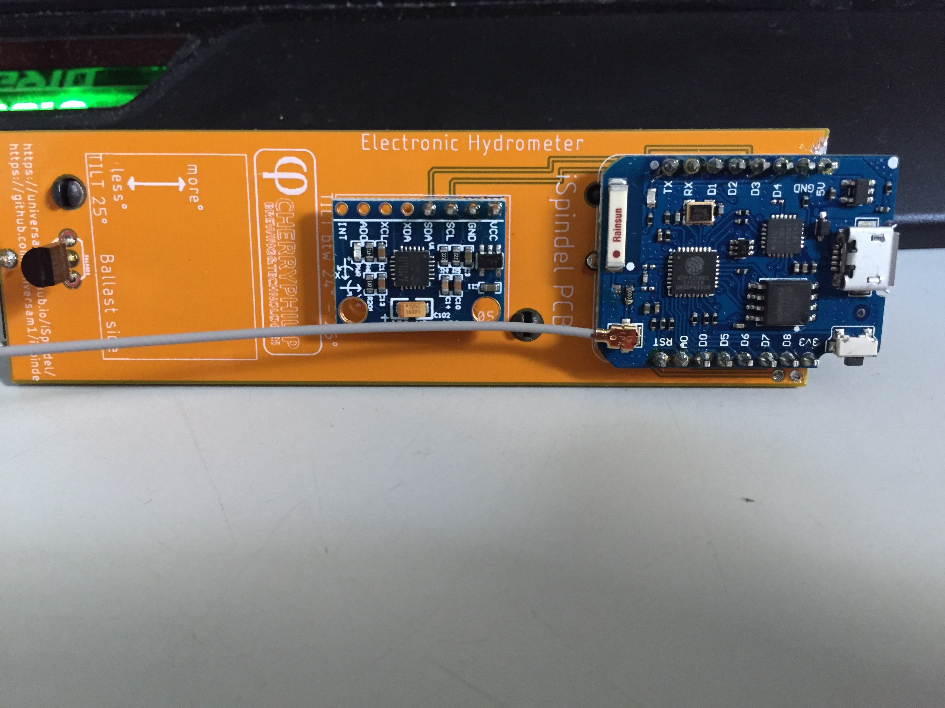
The very early ispindel designs had the charging and programming USB connector toward the lid.
This design meant the aerial was under the wort / beer surface. Signal was not so good on these designs.
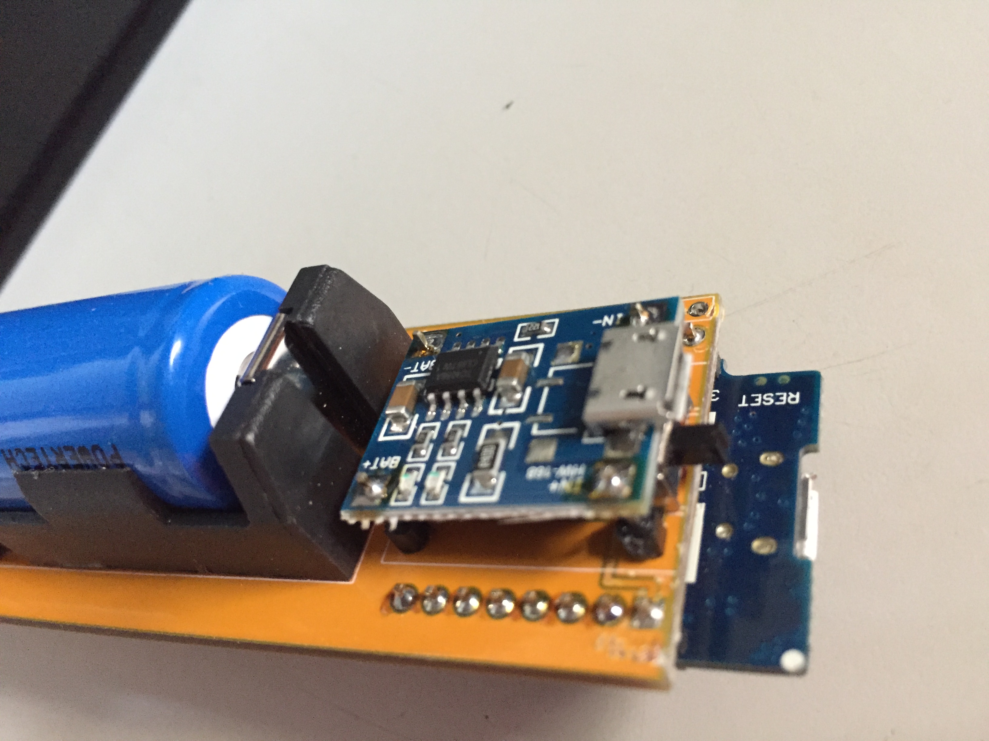
Most are now made using a PCB that all parts are connected to including the battery. No 3d printed sled for these and are much better.
You could also make a repeater using another WiFi router if you had one of those.
 
Does anyone happen to have a single CherryPhilips or Jeffrey PCB I could buy off of them? I have all the parts to assemble another one except the PCB, and don't want to pay for 3 PCBs + shipping from OshPark.
 
Anybody have any long term issues with the on/off switch on their iSpindel? I've just tried 2 of my iSpindels and neither turn on. When I check the battery volts, they're fine, but that voltage is not getting through the switch. If I short out the switch pins everything is fine

So fellow users, where do you get your switches from? What manufacturer do you use? I've had mine so long I can't remember where mine came from, but I suspect China!
So my third iSpindel switch had just died! All 3 were built at the same time a couple of years ago. Is anyone out there using a different switch? Where did you get your switches from?

I've already replaced the switches on 2 of my iSpindels but with switches from the same batch so I'm guessing I'm going to have the same problem down the road. I do have some reed switches which are change over, they have N/O and N/C contacts I think I'm going to try that out.

Unless anyone has any better ideas?
I haven't had switch problems even when a couple of ispindels got damp inside. I'd try the reed switch and use a type that the magnet would turn it off during charging. Would get complicated if you also use a reed switch instead of shorting the pins to access the menu.
 
I'm going to put one my change over reed switches across the faulty switch pins, leaving the switch in place. I'll report my findings...

I checked the source of the switches I have and they are from a reputable UK source. OK they still could be "cheap" switches so I'm still curious where others have sourced their switches and if anyone has had issues?
 
Having a bit of a fight with the reed switch, seems to be very sensitive to positioning. Going to try and source a NC switch and see if that's less sensitive.
 
Having a bit of a fight with the reed switch, seems to be very sensitive to positioning. Going to try and source a NC switch and see if that's less sensitive.
My reed switch for the reset is aligned along length of petling. It is a always off type ? Open until magnet makes the circuit.
 
@DuncB If I remember your reed switch is across the reset pins? I was looking to use the reed switch to replace the on/off switch completely. I might persevere with the change over positioning as I can't find a N/C reed switch yet.

I've got some other switch alternatives "winging" their way to me from China to see if I can sensibly replace the switch with affecting the characteristics too badly.
You can get a reed switch that is normally closed, then it will be open using a magnet = off.
 
You can get a reed switch that is normally closed, then it will be open using a magnet = off.
Seems that most reed switches are normally open, I'm having trouble sourcing a normally closed version. As I said above for some reason the change over reed switches that I already have seem VERY critical on location to operate correctly?
 
Seems that most reed switches are normally open, I'm having trouble sourcing a normally closed version. As I said above for some reason the change over reed switches that I already have seem VERY critical on location to operate correctly?
I got my normally open from this company, they have normally closed ones as well.

https://www.aliexpress.com/item/100...4c16695848906454433e3528!12000026827311833!sh
We had quite a few notes about using a mercury tilt switch earlier in this thread.

One of the below bent at the correct angle would be on at a tilt and heading towards floating vertical. Inverting it would turn it off.

SPST Mercury Switch | Jaycar Electronics New Zealand plenty of them on aliexpress.

I really can't see that the mercury inside a glass switch inside a petling is any risk to the beer.
That change over reed switch is what I have already, but consistent switch off is currently eluding me, more testing required.

A mercury tilt switch is something I don't have in my components drawer so I might get one, got to be better than regularly replacing the switch...
 
Has anyone had an issue where the ESP8266 won't turn on using the battery? It will charge the battery (red LED when charging, blue when complete, not doing the red light on but blue light blinking no battery thing), and will turn on when connected to USB (ESP LED blinks, the 'gravitymon' AP point pops up), but if I try to turn it on in battery mode (but not connected to USB), no dice. The soldering is fine, as far as I can tell.

I'm aware that I need to remove the diode on the ESP8266, will do that after I get it cooperating.
Sounds like a faulty connection between the charge board and the esp. Check the voltage with a multimeter
 
On my previous build ispindels I always removed the diode on the D1 mini but on the once that I've received recently it looks like the diode is no longer there. Could this be possible or is it on another location that I don't notice?

The left one (old version) has a small diode but on the right one (latest version) I can not find it:
20221207_091734.jpg

The top side:
20221207_091710.jpg
 
I can't clearly see from the pictures but it looks like it could be by the reset switch? The component with the "stripe" along one end?

Don't know where the crystal (at least I think it's a crystal) has gone? Maybe the crystal is under the can of the ESP12F?
 
On my previous build ispindels I always removed the diode on the D1 mini but on the once that I've received recently it looks like the diode is no longer there. Could this be possible or is it on another location that I don't notice?

The left one (old version) has a small diode but on the right one (latest version) I can not find it:
View attachment 807314
The top side:
View attachment 807315
You dont need to remove the diode just remember to remove the battery when connecting directly to the esp or you might overload/damage the battery

Im not sure if there is a diode on the newer boards….
 
You dont need to remove the diode just remember to remove the battery when connecting directly to the esp or you might overload/damage the battery
Yes I knew that but I can be a bit scattered sometimes so I still prefer to avoid the worst anyway.
 
Yes I knew that but I can be a bit scattered sometimes so I still prefer to avoid the worst anyway.
See if you can find the schematic from the board manufacturer, that way you should be able to see if they have the diode in place and follow the board traces to the correct component
 
As @ChrisThomas said it looks like the diode to be removed is now between the USB connector and the reset switch.
The crystal on the older D1 mini is needed by the CH340 UART to USB chip,newer versions of the CH340 do not require an external crystal,I am guessing that chip is being used in the newer version D1 mini
 
Hey all

My Rapt Pill just died on me and I want to build an iSpindel. Can anyone recommend a good kit? And any guides/how to's you can link me to?
 
+1 for the OSD PCB and instructions. The eBay link looks like a Cherryphillip PCB which I have made and they've been around a while and also proven. I've built both in the past and in my opinion the OSD are superior in design and buildability.

However, if you don't want to order the parts and PCB yourself and then build it/them, then nothing wrong with getting one ready assembled.
 
So I had just completed calibration using GravityMon and found I had temperature sensor junk readings. So, I removed the battery from the just calibrated unit, see photo, put some tape in to cover the terminals and re-started the calibration by trying to get the board back to the same position in the tube.

Now the problem - the switch does not turn the unit on! I looked back on this thread and replacing the switch could be an option?

Removing the battery and powering the Wemos from the USB - GravityMon works.

Unplugging the USB then replacing the battery and it shows green light on the charger, battery measures 4.22V.

I think that the switch might be the problem.

My question is what would be my best option? As on the face of it to replace the switch will require a lot of unsoldering! And potential damage to the Wemos.

Thanks
IMG_2192.JPG
 

Attachments

  • IMG_2190.JPG
    IMG_2190.JPG
    1.3 MB · Views: 0
  • IMG_2191.JPG
    IMG_2191.JPG
    1.2 MB · Views: 0
So I had just completed calibration using GravityMon and found I had temperature sensor junk readings. So, I removed the battery from the just calibrated unit, see photo, put some tape in to cover the terminals and re-started the calibration by trying to get the board back to the same position in the tube.

Now the problem - the switch does not turn the unit on! I looked back on this thread and replacing the switch could be an option?

Removing the battery and powering the Wemos from the USB - GravityMon works.

Unplugging the USB then replacing the battery and it shows green light on the charger, battery measures 4.22V.

I think that the switch might be the problem.

My question is what would be my best option? As on the face of it to replace the switch will require a lot of unsoldering! And potential damage to the Wemos.

Thanks
You are not the only one affected by bad quality switches.

you risk damaging the board if you try to unsolder the parts (unless you are skilled at that) to replace the switch. I would suggest that bypassing the switch is your best option and remove the battery when not in use.

You need to connect the output (+) of the charging board to the +5V on the wemos

another option I covered in my documentation is to use a reed switch (magnetic switch) when bypassing the switch. If you choose one that is normally closed it will work and if you place a magnet close to the reed switch it will be turned off.

Hardware - GravityMon v1.2.0
Thanks I have tried the bypass and that seems to work and have also ordered a NC reed switch
Cheers
 
Last edited:
@korev
The reed switches are fragile bending the wires so bend the wire away from the little glass bulb.

The blue tape is that covering up the temp sensor wires that are prominent on that side of the board.

If so I think on the how to build part of the open source distilling site they have how to solder flat so you don't get that wire sticking up issue.
Thanks for the tip - the reed switches will be arriving March hopefully
Yes, Blue tape covers the temp sensor terminals - inherited iSpindel!

Photos of my bodged temporary switch attached
 

Attachments

  • IMG_7848.JPG
    IMG_7848.JPG
    1.2 MB · Views: 0
  • IMG_7849.JPG
    IMG_7849.JPG
    1.2 MB · Views: 0
@korev
To be honest what more do you really need as a switch. With the gravity mon I think you can easily set the time interval live to different times, so you could just change to a many hours rather than seconds of update when it's not in a ferment. Just leave it constantly on then.
On the ispindel software I used the reed switch instead of the contacts for triggering the local network to adjust configuration.
That allowed me to change the interval with a magnet during a ferment.

I've switched to the GravityMon firmware and enabled the option to sleep forever when you put the device cap down.
This is because I've had the switch fail on multiple devices, and this allows me to just short the switch rather than trying to replace it. You only need to leave it cap down for 15-30 minutes until it goes to sleep. You can turn it back on when you want to use it again by shorting the reset pins for a few seconds, which I usually do after charging it.
 
I have a weird issue that I'm hoping someone can give me some pointers about. I've soldered up 2 Jeffrey 2.69 PCBs with Lolin ESP32 C3 V2.1 minis. One works fine, the other one not so much. Successfully flashed, but it won't open the "GravityMon" AP point using the GravityMon 1.2 firmware on battery power. When I connect it to my laptop via USB, it boots up just fine, opens the AP point, etc. So it's some issue with battery power getting to the ESP32, right?

I checked the non-cooperative ESP32 with a multimeter, and I get the same 4.11v reading that I do when just testing the battery. In addition, when I turn it on, the LED on the gyroscope lights up, so it's not just a dead battery or improperly seated battery holder, or an issue with the switch. In addition, the battery fully charges, so don't think it's an issue with the TP4056.

Comparing the soldering between the working and non-working ones, I don't see anything obvious, like bridged pins or something like that. Any pointers would be greatly appreciated.
Can you hook up a serial monitor and send me the result on the faulty one, remove any passwords etc.

could be a boot issue with the bootloader or crash at startup or faulty chip
 
FYI Just built a new iSpindel with a NC Reed switch - seems to work OK
 

Attachments

  • IMG_2275.MOV
    23.9 MB
  • IMG_2272.JPG
    IMG_2272.JPG
    1.1 MB · Views: 0
  • IMG_2273.JPG
    IMG_2273.JPG
    889.4 KB · Views: 0
I have uploaded the iSpindel firmware but failing to get an access point. It's been a while so my memory might be foggy. I used to be able to upload the firmware and access 194.168.4.1 even with nothing connected.

I have tried flashing different versions on several esp8226 board. Each time I can only get the ESP-CA... on a wifi signal not the normal iSpindel AP. I have used the node mcu flasher and done the INTERNAL://NODEMCU and INTERNAL://BLANK before uploading firmware. I have used Brewflasher too.

This is the error message over Arduino IDE serial monitor:
FW 7.0.0
2.2.2-dev(38a443e)
Worker run!
mounting FS... mounted!
ERROR: failed to load json config

ERROR config corrupted
scanning for OW device on pin: 5
No devices found!
scanning for OW device on pin: 12
No devices found!
scanning for OW device on pin: 0
No devices found!
scanning for OW device on pin: 0
No devices found!
ERROR: cannot find a OneWire Temperature Sensor!
Acc Test Connection ERROR!
offsets not available
Boot-Mode: Deep-Sleep Wake

I am at a loss. I am not really worried about the errors for things not yet connected. The failed to load json config I am concerned about but have run out of ideas.
 
Back
Top