iSpindle - DIY Electronic Hydrometer

Homebrew Talk - Beer, Wine, Mead, & Cider Brewing Discussion Forum

Help Support Homebrew Talk - Beer, Wine, Mead, & Cider Brewing Discussion Forum:

This site may earn a commission from merchant affiliate links, including eBay, Amazon, and others.
mmmmm
my big momas just turned up today. I bought these and will have to see if i can get them to work.
WARNING-not the same as the german ones
http://www.ebay.com.au/itm/17169215...49&var=470660824753&ssPageName=STRK:MEBIDX:IT

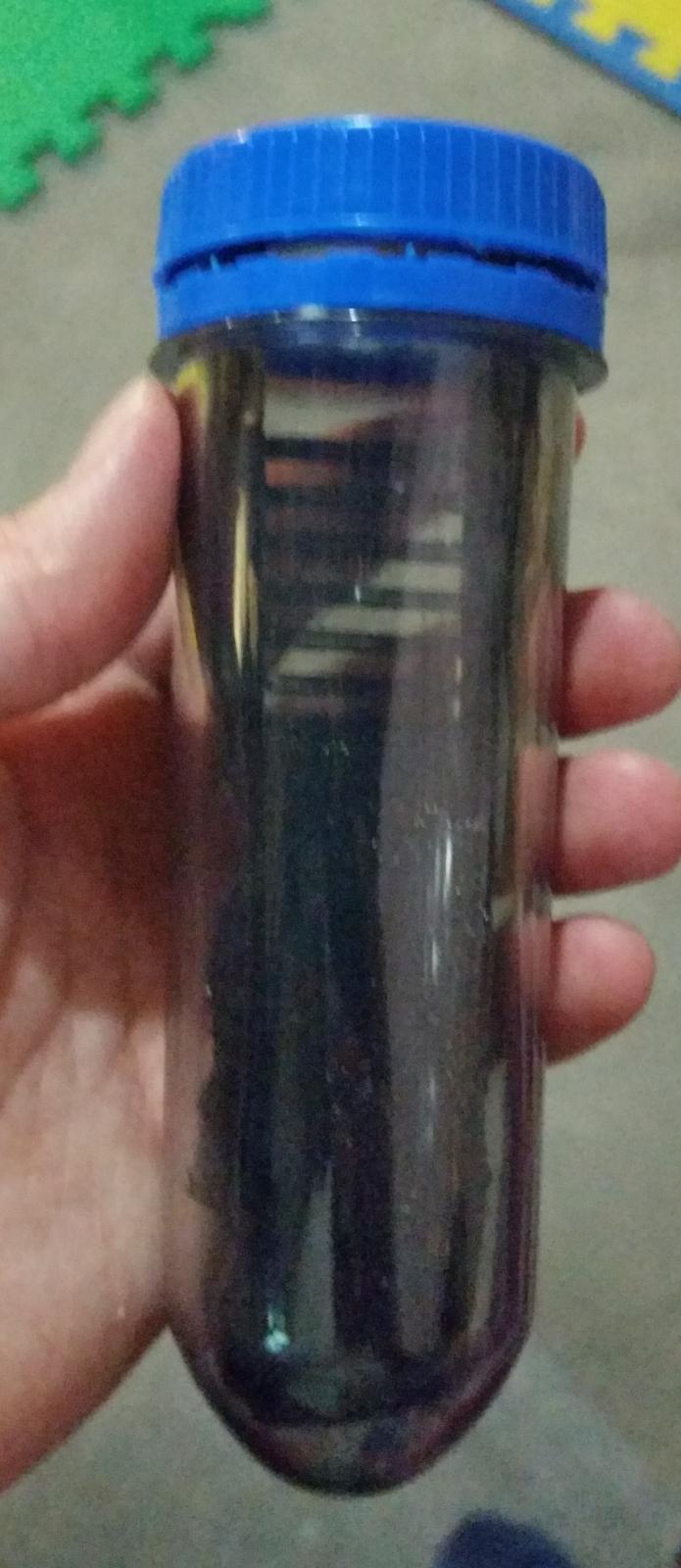
Biggest-Preform-Geocache-Container-Pack-of-10-or-20-With-Lids-200mm-Long
They are 200mm from top of cap to bottom external
od of tube 36-38-36mm
ID of tube 31mm wemos is 25mm or so wide

if no good maybe ill stick hops in them.
 
I WA wondering wether some sort of sliding design for the battery holder might make trimming easier
Also can you fill your tube up with water and measure the mls capacity pls?
 
I'm in the middle of a build of this now. I've changed up the parts a little bit but the idea is pretty much the same.

I've complied and uploaded the script to the wemos and am able to get to the wifi configuration script using it as an IP, but after that, when it attempts to connect to my internal wifi network I can't seem to connect again. I don't see anything come up in the arduino IDE console that helps.

Any ideas?
 
I WA wondering wether some sort of sliding design for the battery holder might make trimming easier
Also can you fill your tube up with water and measure the mls capacity pls?

looks like if i fill it up to the top and cap it its 148ml
 
so...what do you guys think? the space at the bottom is for the 20g weight, hopefully ill print it again and test it out soon.

https://www.tinkercad.com/things/1TcD78DvxQu

My .002

1. what if 25g or more is needed? I red the documents on Github and saw two numbers: 15 and 25 degree. Mine tilts around 30 degree by using 20g, and I am going to use 25g. (There is not much space, so I am going to use wheel balancing blocks.)

2. Is it possible to design a sled that can fit a battery holder instead of the battery? Li-on battery is not stable. Soldering the battery seems dangerous to me.

1. well i weighted the rest of the thing i do have(sled, bottle, battery, wemos and some boards) and it weighted around 5.6g, so with the 20g i would figure that it would might hit the 30g total weight easier, but everything is trial and error, if it needs a 25g i might just need to modify it until i get a perfect sled for repeatable results.

2. yea if you can get the size of the holder you can print out a square hole were it can fit perfectly, also you dont really have to solder, you can just put some black tape on it on each end and would be fine if it doesnt move alot
 
It may not be the prettiest of jobs, and I'm still waiting on the Peltier, but it works.

well when I say works it does work, infact it's always on and switch seems to do nothing, and I can't tell whether the device is charging the battery when it's powered on, but it's logging and I'll take that.

IMG_8159.jpg
 
Now thats looking pretty cool.
Does your sled make the battery sit at the bottom of the tube?
Was wondering because our german mates talk about weighting the tube and if yours goes to the bottom is there enough room to put weights?
Also an optimum starting angle of 25 deg is talked about, attained by adding weights i think.
Can i get a copy of your sled drawing cad? file? I would like to edit it for my tubes and print some. thanks
 
Mikmonken,

When you built your iSpindel, did you remove the diode from the Wemos and the LED from the GY-521? If so, any hints on doing that?
 
Ok trying to respond to all three

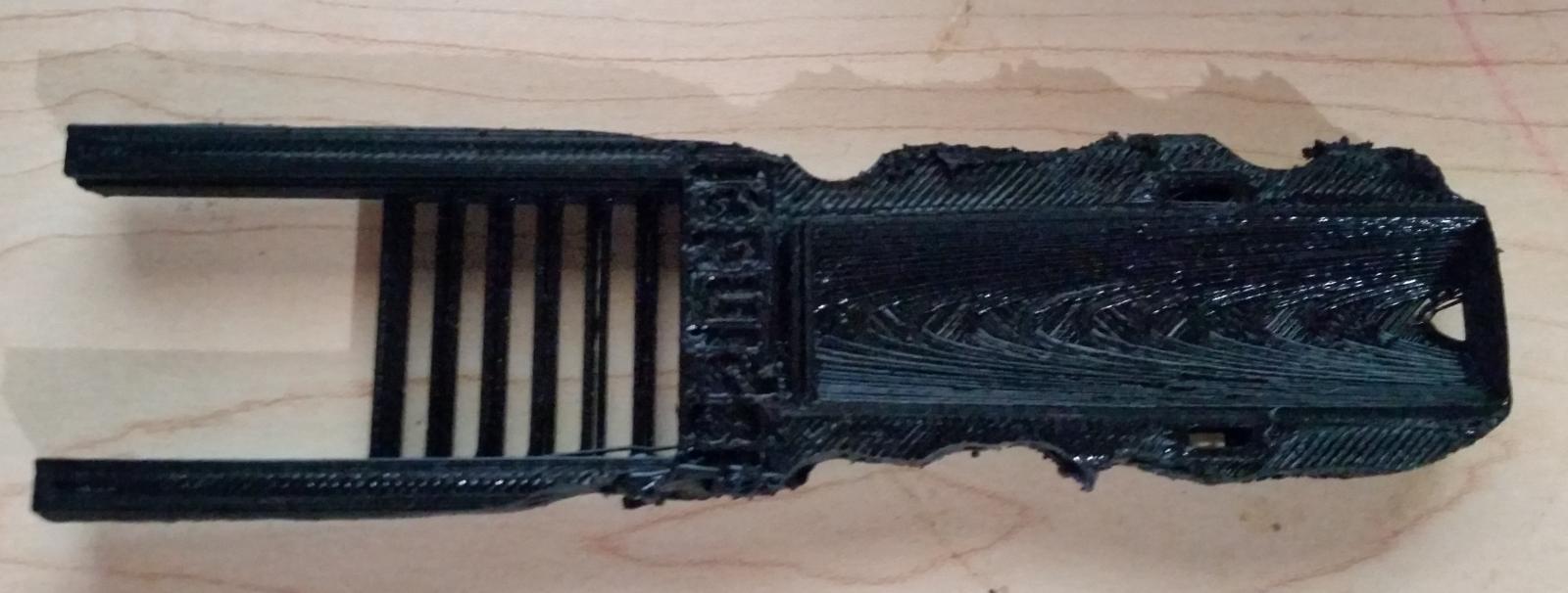
First off I bought the 3D sled from the European distributor it's pretty poor quality and has split already I'll measure it tomorrow and let you know how long it is,

the eBay pelting hasn't arrived yet so I can't say whether it fits but if the eBay dimensions are right it should do.

I used wire cutters to get rid of the diodes and led I felt more comfortable doing that than holdering a solder iron to them and melting them off. I have no idea whether this is good practice or not and as mentioned my device switch doesn't work so it may not be.
 
Ok trying to respond to all three

First off I bought the 3D sled from the European distributor it's pretty poor quality and has split already I'll measure it tomorrow and let you know how long it is,

the eBay sled hasn't arrived yet so I can't say whether it fits but if the eBay dimensions are right it should do.

I used wire cutters to get rid of the diodes and led I felt more comfortable doing that than holdering a solder iron to them and melting them off. I have no idea whether this is good practice or not and as mentioned my device switch doesn't work so it may not be.
Are you still using the Ebay tube you linked to in an earlier post?If not what tube are you using?
 
The length wasn't the issue it was the width of the tray...took the dremel to it tonight...it fits now but who knows if this is going to throw off the tilt..lol

tray.jpg


pet.jpg
 
The length wasn't the issue it was the width of the tray...took the dremel to it tonight...it fits now but who knows if this is going to throw off the tilt..lol

i warned you all that it didnt fit! lol still havent gotten my new sled yet but they sent me a picture

17579901_1871078689841190_1696635558_n.jpg
 
Are you still using the Ebay tube you linked to in an earlier post?If not what tube are you using?

still waiting for the pelting container, but it was the version that I linked to from eBay that ElChangoGuero says is the wrong size.
 
In your printed sleds, does the sled hold the battery on an angle to give it some initial tilt? looks like it from the diagrams.

Yes, it is at a slight angle, probably to expose the end for when you solder a wire to it. Photo attached, shows how far the printed sled goes in before it jams. Probably just needs a small amount of material to be filed off for it to go in all the way.

Got lots of resistors from China already, waiting for the main components...

**UPDATE**
This tip just in from Sam from the iSpindle project - try this before you take a Dremel to your sled and shred it:

...But here is the trick, put the sled into hot water ~140°F where it gets soft, then push it gently into the sled. Repeat it if necessary, you will squeeze it until it fits. Not perfect but works!

** UPDATE x2 **
I actually tried it, put water in a ceramic dish, floated the sled on the water and put it in the microwave on the beverage setting and it worked well to soften up the material so it could fit the tube, however the sled legs splayed out a little (warped) so flipped it over and pressed it back into shape and that seems to have fixed that issue. I'll find out when I get the circuit board but shouldn't be too difficult to reform it.

iSpindle_Sled.jpg
 
Last edited:
As a hobbyist, I recommend KiCAD. It's free and has no board or layer limits. There is a bit of a learning curve though. If you need any help, just ask. I'm no expert, but can make my way through it.

Wow it's a learning curve alright, but I think I'm doing OK.

created a scheema the other day and thought it was all OK, but apparently I hadn't connected my wires to exactly the right place so when I went to create a board it spat it's dummy out.

having a bit of trouble finding all the right components, the toy switch too, I know I could create them, but to be honest I have no clue apparent electronics and wha the symbols mean etc so it's easier for me to find them through other peoples posts.

hopefully at some point in the near future I'll have created my first board.

Fritzing was so much easier, although the spacing on the toy switch footprints would have been all wrong, but I can appreciate whys it's not the best tool for the job having seen some of the other designs people have done.
 
Wow it's a learning curve alright, but I think I'm doing OK.
<snip>
having a bit of trouble finding all the right components, the toy switch too, I know I could create them, but to be honest I have no clue apparent electronics and wha the symbols mean etc so it's easier for me to find them through other peoples posts.

Message me with any questions (as to not clutter up this thread)
As I said, I'm no expert. But I can make my way through it, and would gladly help you with component creation.

I'm not familiar with the toy switch. Do you have a link or cutsheet that I can reference? I'll take a look and see what it may take.

Edit: After looking at your Aliexpress List, it looks like it's just a 3 pin component with a lead spacing of 2.54mm (or .1"). You could simply use a 3-pin header for the toy switch.
 
I have no idea what sled I have or even if it's on the GitHub but the one I posted earlier fits like a glove in the eBay sled, my shoddy soldering however he meant that the battery became disconnected and then somehow killed the ESP when it kept touching the base. New ESP and gyu board ordered to rebuild.
 
Did you get anything out of it before you killed it? My bits are arriving but very slowly
I stuck the battery in the tube to see how it floats. I can see why they need weights to get it to 25 deg in plain water.
 
well, what a freaking horrible experience with soldering, think i finished it "correctly", do not solder the temperature sensor until you are almost finished, can be a pain due to the height, next time i would probably wait on removing the LED after testing, since now i cant even tell when anything is on lol, you can still remove the LED when its all together with no problem

IMG_20170403_180825.jpg
think the angle is still a little off

still need to program and test, has anyone flashed and got this to work successfully?

edit: was able to setup the wemos on ubidots and get data(temp, inclination, battery) only works when connected directly though to a usb on my laptop, will redo the circuit board
 
Did you get anything out of it before you killed it? My bits are arriving but very slowly
I stuck the battery in the tube to see how it floats. I can see why they need weights to get it to 25 deg in plain water.


Yep I got it all wired up a few days ago and was waiting for the pelting. Only the switch didn't seem to work.

Connected to ubidots and it was working fine.

I agree about not removing the leds on the lipo charger as I couldn't tell if that was working unless it was plugged in and I was looking at the voltage on the website but you need to take the diode off the wemos as otherwise it can be a fire hazard.

You can see if it's working by pressing the wemos reset button as the little blue light will flash on it just below the GYU." Chip
 
Yep I got it all wired up a few days ago and was waiting for the pelting. Only the switch didn't seem to work.

did you connect the orange wire like in the original german schematics? just noticed it trying to figure this out

Schematic.jpg
"Eingangsdiode entfernen und verbindung (orange) an Lotpunkt, der vom USB kommt, anloten (Ruckseite)"

"Remove the input diode and connect (orange) to the solder point coming from the USB (reverse)"

Looks like there is a soldering dot at the bottom of the wemos mini?

Screenshot 2017-04-03 23.16.49.png
 
Diagram not clear but says below

Battery charging module
•Battery to B + and B-
•GND -> GND
• + OUT switch to + 5V Wemos D1 mini
• + IN to USB + 5V of the Wemos D1 mini (optional)

Not sure why it's optional
 
did you connect the orange wire like in the original german schematics? just noticed it trying to figure this out

View attachment 395227
"Eingangsdiode entfernen und verbindung (orange) an Lotpunkt, der vom USB kommt, anloten (Ruckseite)"

"Remove the input diode and connect (orange) to the solder point coming from the USB (reverse)"

Looks like there is a soldering dot at the bottom of the wemos mini?

View attachment 395228

No I didn't, but it explains how I've made a mistake, I think I've ballsed something up to do with the switch where I thought that the middle pin of the switch needed connecting to the live which I thought made no sense at the time.
 
did you connect the orange wire like in the original german schematics? just noticed it trying to figure this out

View attachment 395227
"Eingangsdiode entfernen und verbindung (orange) an Lotpunkt, der vom USB kommt, anloten (Ruckseite)"

"Remove the input diode and connect (orange) to the solder point coming from the USB (reverse)"

Looks like there is a soldering dot at the bottom of the wemos mini?

View attachment 395228

That's not a soldering dot. It's called a fiducial. There is another one on the upper right corner. These are used as optical alignment identifiers for the pic and place machines to orient themselves to the board for proper component placement. The copper pad won't be connected to anything electrically.
 
Back
Top