• Please visit and share your knowledge at our sister communities:
  • If you have not, please join our official Homebrewing Facebook Group!

    Homebrewing Facebook Group

How To: BrewPi LCD Add-On

Homebrew Talk

Help Support Homebrew Talk:

This site may earn a commission from merchant affiliate links, including eBay, Amazon, and others.
Thanks @day_trippr. The part where the diodes light when grounded makes sense. I am less good on why they don't light all the time when connected to the D5/6. Don't those connections also provide a path to ground via the relay coils (IN1/2)? I mean, I believe it works, it obviously does, and you make your living doing this; I just don't understand how it works. :)

Oh wait ... glimmer of understanding ... are D5/6 "grounds" for that circuit? I'm probably using the wrong terminology but if the coils are energized via VCC and the circuit is completed via D5/6 to ground, I guess that makes sense.
 
"Saved by the glimmer!" :)

You got it. The (current-limited) 5V on the LED anode means grounding the cathode will light it up, and as we operate the GPIO pins to the relays using the low-active state, if the switches are thrown to "Auto" mode the LEDs will light when their corresponding relays are picked. In the "On" mode the cathodes are shorted to GND, and in the "Off" mode they're floated...

Cheers!
 
has anyone noticed that the forum.brewpi.com server is down? I'm hoping it's just a maintenance issue, if not, perhaps we need to start pooling resources for these builds somewhere?
 
Can someone, please explain how to do this on rpi :"On your raspberry Pi, the file "pinList.py" and "pinList.pyc" located at /home/brewpi should be deleted and replaced with "pinList.py" from the aforementioned repository."
 
Found it after a while searching. Any chance there's a wiring diagram for i2c/encoder/pi/arduino config? I'll look through and post a link in this post if I find.
 
Can someone please upload hex file for use with i2c lcd screen with arduino uno.

thanks
 
Thanks mang, had hex but couldn't find definitive file. I'm guessing I'll post that for posterity. You're the man!

File = wiring diagram.
 
I had a suggestion - just in case someone was thinking of making a new version of the shield. (Lord knows I've beat my head against Eagle enough that I don't believe I'm the right guy to try):

Include an RJ-11 Jack to simplify wiring. I think enough folks have moved to this to make it "a good idea." The ubiquity of the connectors and splitters makes it very easy to implement into the design. There's a pseudo-standard that's been used by a lot of folks. The RJ-11 can support the door switch as well as the probes making it a real clean deployment.

Adding it where it makes sense (the side where the power is) would mean moving the LCD header - which makes this way out of my league to pull off.

If I was to get my wishes, I'd also make two more changes: A header for the rotary encoder, and make the mosfet a through-hole type to simplify the soldering for those of us with less than 20:20 vision and not-so-steady hands. I'm sure there's probably a good reason why that microscopic thing was chosen.

Just morning musings. Someday someone might give some of this a shot so I thought I'd most my thoughts. Don't get me wrong, I REALLY appreciate the current shield that @CadiBrewer put together for us. It works great!
 
I don't get the advantage of bulky PCB mounted phone jacks when the same signals are going to be passed through a case...

Cheers!
Because if you mount it so that the jack is accessible outside the case, you use a standard interlocking connection, and you reduce the number of interconnections by one.

You've already (arguably) got the power and USB accessible externally with a well-designed box. Having a phone jack there puts all of the external connections in one place.

If the pins were left on the board to allow for the dupont connectors you prefer, that would provide the best of both worlds I suppose. I can see where in your installations this might not be an advantage but in mine (and many I have seen) it would.
 
I don't get the advantage of bulky PCB mounted phone jacks when the same signals are going to be passed through a case...

Cheers!

Because if you line it up with a hole in the case you don't need any internal wiring.

Having said that, I used these (sadly no longer in stock):
http://www.dx.com/p/rj11-wall-socket-panels-voice-modules-w-amp-interface-white-green-4-pcs-296681

The screw terminals allowed me to attach DuPont cables to connect to my Pi GPIO, and I could trap the legs of my 4k7 pull-up resistor in there too. An RJ11 1-wire panel-mounted socket with no soldering. Result!
 
I'm busy with work and house projects for the next month or so, but if no one has taken a crack at the board revisions by then, I'll give it a go. I've wanted to swap out the p-fet for the through-hole mount PNP transistor. Adding a header for the encoder should be a snap. Moving the LCD header to accomodate an RJ11 panel mount input might cause a full re-design, but I'll give it a go. No reason why we can't have two versions of the board, one for those (like me) who use connectors on the outside of our enclosures and another for those who want to have the inputs on the board accessible from the exterior.

Edit: After quickly looking at my board, moving the LCD header might not be as challenging as I thought. The build only uses pins 1-6 and 11-16 on the LCD screen. I designed the board with a 16 pin header for ease of just lining up all of the pins from the LCD with the pins on the header and using a ribbon cable instead of individual wires. But there is no reason I can't use a 12 pin header on the board with silkscreen labels showing which pin numbers to use from the LCD screen. Or for that matter, I could even split it up into two separate headers for ease of placement on the board. I'll take a look at it if I have some time. Don't hold your collective breath...
 
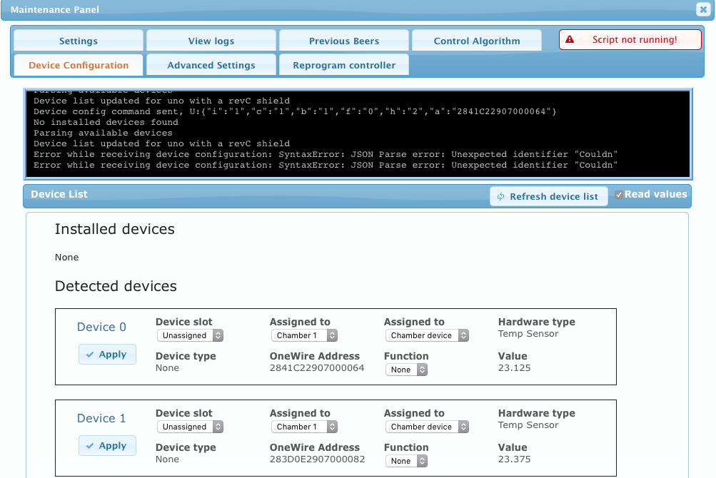
I can't start it and it gives error when refreshing device list. It all happened after replacing the pinlist.py
 
So I have done all the steps based on DAY_Tripper's recommendations, replaced pinlist.py and deleted pinlist.pyc, flashed my arduino, am able to see temps in the device list but I can't "install" them... so weird... any ideas? Then this happens...

Screen Shot 2016-10-30 at 8.38.11 PM.png
 
I'm busy with work and house projects for the next month or so, but if no one has taken a crack at the board revisions by then, I'll give it a go. I've wanted to swap out the p-fet for the through-hole mount PNP transistor. Adding a header for the encoder should be a snap. Moving the LCD header to accomodate an RJ11 panel mount input might cause a full re-design, but I'll give it a go. No reason why we can't have two versions of the board, one for those (like me) who use connectors on the outside of our enclosures and another for those who want to have the inputs on the board accessible from the exterior.

Edit: After quickly looking at my board, moving the LCD header might not be as challenging as I thought. The build only uses pins 1-6 and 11-16 on the LCD screen. I designed the board with a 16 pin header for ease of just lining up all of the pins from the LCD with the pins on the header and using a ribbon cable instead of individual wires. But there is no reason I can't use a 12 pin header on the board with silkscreen labels showing which pin numbers to use from the LCD screen. Or for that matter, I could even split it up into two separate headers for ease of placement on the board. I'll take a look at it if I have some time. Don't hold your collective breath...


Nice I'd like to see the board design with the changes :) The less wires or not wires in the inside the cleaner and nicer it will look esp in a clear box :) Then it could be pimped with a couple of led lights to make it glow at night :) how long can you redesign the basic changes? :)
 
so i've gotten my 4x20 LCD to display garbled characters (just randomly walking across the screen) and for th live of me, i can't figure out what's wrong here. no relays plugged in, nothing, just breadboard. I thought it might be the power but i've got a 5V 3A supply powering the pi. any further ideas would be greatly appreciated.

View attachment ImageUploadedByHome Brew1477941026.590759.jpg
 
so i've gotten my 4x20 LCD to display garbled characters (just randomly walking across the screen) and for th live of me, i can't figure out what's wrong here. no relays plugged in, nothing, just breadboard. I thought it might be the power but i've got a 5V 3A supply powering the pi. any further ideas would be greatly appreciated.

Same advise I always give: the design works, so you have a wiring error somewhere.
Start with the power & ground connections to the shift register, then the shift register input signals from the Arduino, then the outputs from the shift register to the LCD. You'll find it eventually...

Cheers!
 
Same advise I always give: the design works, so you have a wiring error somewhere.

Start with the power & ground connections to the shift register, then the shift register input signals from the Arduino, then the outputs from the shift register to the LCD. You'll find it eventually...


Cheers!


Lived this. Design is solid. Check your wires - again.
 
It is kinda how I feel. I think I have to commit to a Protoboard instead of doing it on a bread board and hard wiring connections one at a time.
 
Yeah, that's the pain in the backside part, but have to say, the payoff when it works is worth it.

Surprised that nobody has taken the mighty initiative and done a printed PCB for these yet, akin to what's going on in the ESP8266 thread? I know it's Elco's baby, but given the fact that the platform has essentially been abandoned by him in favour of the Spark platform, would it not be considered "fair game" or is it still potentially taking money out of his pocket?

I took the initiative and removed the Arduino entirely. No PCBs, no shields, everything wired directly to Pi GPIO with DuPont cables.

All you really need is a Pi and a dual relay board, then you can do everything via the web interface. Adding an LCD is easy, as there are many modules that will plug in to the GPIO (I used an old Nokia cellphone display as they are very cheap).

The long-running "How to make a BrewPi controller for cheap" thread may or may not have been taking money out of Elco's pocket. It certainly has raised awareness of BrewPi, but it was his decision to open-source it, which comes with benefits and drawbacks. Hopefully the benefits outweigh the drawbacks and he's doing ok.
 
I'm still interested in taking a crack at it. I'm just working my way through my problem so I can make a board that will work.
 
Back
Top