Ask away - we're talking past each other, and such discussion can only enhance things for everyone.Should I just list specific questions? I didn’t want to bog down the thread if such documentation exist, rather than asking a bunch of individual questions.
You are using an out of date browser. It may not display this or other websites correctly.
You should upgrade or use an alternative browser.
You should upgrade or use an alternative browser.
Fermentrack: Fermentation monitoring & BrewPi-www Replacement for Raspberry Pi
- Thread starter Thorrak
- Start date

Help Support Homebrew Talk:
This site may earn a commission from merchant affiliate
links, including eBay, Amazon, and others.

Popcorn is ready!
Cheers!

- Joined
- Sep 8, 2020
- Messages
- 139
- Reaction score
- 9
Ask away - we're talking past each other, and such discussion can only enhance things for everyone.
First question:
What is the ‘estimator’? Is that the PID K values? This question relates to both the heating and cooling upper limits.
Attachments

(Trying to get my mule to run with Fermentrack again so I can look.)
- Joined
- Jan 13, 2014
- Messages
- 563
- Reaction score
- 91
Estimator is an additional algorithm on top of PID. It measures heating/cooling speed and turns heating/cooling off before temperature reaches target value based on that measurement.First question:
What is the ‘estimator’? Is that the PID K values? This question relates to both the heating and cooling upper limits.
What you describe there is the "Derivative" component of the PID loop. I don't think it's outside the normal PID process.Estimator is an additional algorithm on top of PID. It measures heating/cooling speed and turns heating/cooling off before temperature reaches target value based on that measurement.

$10.99 ($31.16 / Ounce)
Hornindal Kveik Yeast for Homebrewing - Mead, Cider, Wine, Beer - 10g Packet - Saccharomyces Cerevisiae - Sold by Shadowhive.com
Shadowhive

$44.99
$49.95
Craft A Brew - Mead Making Kit – Reusable Make Your Own Mead Kit – Yields 1 Gallon of Mead
Craft a Brew


$22.00 ($623.23 / Ounce)
AMZLMPKNTW Ball Lock Sample Faucet 30cm Reinforced Silicone Hose Secondary Fermentation Homebrew Kegging joyful
无为中南商贸有限公司


$53.24
1pc Hose Barb/MFL 1.5" Tri Clamp to Ball Lock Post Liquid Gas Homebrew Kegging Fermentation Parts Brewer Hardware SUS304(Gas MFL)
Guangshui Weilu You Trading Co., Ltd


$176.97
1pc Commercial Keg Manifold 2" Tri Clamp,Ball Lock Tapping Head,Pressure Gauge/Adjustable PRV for Kegging,Fermentation Control
hanhanbaihuoxiaoshoudian


$33.99 ($17.00 / Count)
$41.99 ($21.00 / Count)
2 Pack 1 Gallon Large Fermentation Jars with 3 Airlocks and 2 SCREW Lids(100% Airtight Heavy Duty Lid w Silicone) - Wide Mouth Glass Jars w Scale Mark - Pickle Jars for Sauerkraut, Sourdough Starter
Qianfenie Direct


$58.16
HUIZHUGS Brewing Equipment Keg Ball Lock Faucet 30cm Reinforced Silicone Hose Secondary Fermentation Homebrew Kegging Brewing Equipment
xiangshuizhenzhanglingfengshop


$479.00
$559.00
EdgeStar KC1000SS Craft Brew Kegerator for 1/6 Barrel and Cornelius Kegs
Amazon.com


$159.99 ($26.66 / Count)
3M High Flow Series System BREW120-MS, 5616001, For Brewed Coffee and Hot Tea, Valve-in-Head Design
SpaceCityProviders


$7.79 ($7.79 / Count)
Craft A Brew - LalBrew Voss™ - Kveik Ale Yeast - For Craft Lagers - Ingredients for Home Brewing - Beer Making Supplies - (1 Pack)
Craft a Brew


$76.92 ($2,179.04 / Ounce)
Brewing accessories 1.5" Tri Clamp to Ball Lock Post Liquid Gas Homebrew Kegging Fermentation Parts Brewer Hardware SUS304 Brewing accessories(Gas Hose Barb)
chuhanhandianzishangwu

$20.94
$29.99
The Brew Your Own Big Book of Clone Recipes: Featuring 300 Homebrew Recipes from Your Favorite Breweries
Amazon.com

$719.00
$799.00
EdgeStar KC2000TWIN Full Size Dual Tap Kegerator & Draft Beer Dispenser - Black
Amazon.com


![Craft A Brew - Safale BE-256 Yeast - Fermentis - Belgian Ale Dry Yeast - For Belgian & Strong Ales - Ingredients for Home Brewing - Beer Making Supplies - [3 Pack]](https://m.media-amazon.com/images/I/51bcKEwQmWL._SL500_.jpg)


$53.24
1pc Hose Barb/MFL 1.5" Tri Clamp to Ball Lock Post Liquid Gas Homebrew Kegging Fermentation Parts Brewer Hardware SUS304(Liquid Hose Barb)
yunchengshiyanhuqucuichendianzishangwuyouxiangongsi


- Joined
- Jan 13, 2014
- Messages
- 563
- Reaction score
- 91
Not exactly. "Derivative" component take in account only previous value and can't handle longer history like a control signal prorogation delay. Also "D" only add or subtract some value from control signal but can't switch it off completely since it also a "I" and "P" components.What you describe there is the "Derivative" component of the PID loop. I don't think it's outside the normal PID process.
Please check here, for example brewpi-remix/brewpi-firmware-rmx
Sounds like you already have the answers then.
rkhanso
Well-Known Member
- Joined
- Jan 24, 2017
- Messages
- 785
- Reaction score
- 178
Will Fermentrack work with a display like this? https://www.amazon.com/Dorhea-Display-3-3V-5V-Arduino-Raspberry/dp/B07FK8GB8T/ref=sr_1_10?
Or maybe this one? Amazon.com
Or do I need to stick with a 16x2 or 20x2 LCD display with I2C (or with an i2c adapter)?
I have an old Newhaven LCD display, but no I2C adapter board for it. I thought if I have to buy one, maybe I can just get the cool looking display instead. I'm using a D1 ESP controller.
Bigdaddyale
Well-Known Member
OLED is not compatible with FermentrackWill Fermentrack work with a display like this? https://www.amazon.com/Dorhea-Display-3-3V-5V-Arduino-Raspberry/dp/B07FK8GB8T/ref=sr_1_10?
Or maybe this one? Amazon.com
Or do I need to stick with a 16x2 or 20x2 LCD display with I2C (or with an i2c adapter)?
I have an old Newhaven LCD display, but no I2C adapter board for it. I thought if I have to buy one, maybe I can just get the cool looking display instead. I'm using a D1 ESP controller.
- Joined
- Jan 13, 2014
- Messages
- 563
- Reaction score
- 91
OLED is not compatible with Fermentrack
It's not too hard to implement OLED support but that particular display is too small. To fit all required info you will need to use really tiny font.
Bigdaddyale
Well-Known Member
There are better options if you need to use OLED.
rkhanso
Well-Known Member
- Joined
- Jan 24, 2017
- Messages
- 785
- Reaction score
- 178
Thanks for all the info. I didn't realize those things were so small. The largest I found at a decent price on Amazon was 2.8"
I'll stick with the standard LCD 20x4 then.
I'll stick with the standard LCD 20x4 then.
Troubleshooting Fermentrack logging.
I successfully added a ds18b20 sensor to my esp8266. But when I started a new logging session nothing shows up as a trend on the Dashboard screen. I was logging one previously without a problem. Any Ideas?
I successfully added a ds18b20 sensor to my esp8266. But when I started a new logging session nothing shows up as a trend on the Dashboard screen. I was logging one previously without a problem. Any Ideas?
Troubleshooting Fermentrack logging.
I successfully added a ds18b20 sensor to my esp8266. But when I started a new logging session nothing shows up as a trend on the Dashboard screen. I was logging one previously without a problem. Any Ideas?
Never mind a reboot of the Rpi fixed it.
rkhanso
Well-Known Member
- Joined
- Jan 24, 2017
- Messages
- 785
- Reaction score
- 178
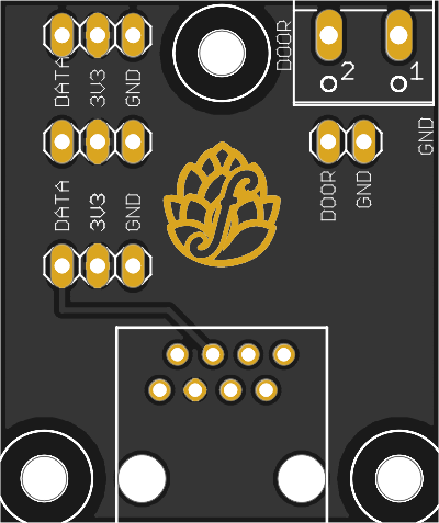
I just picked up some of Thorrak's breakout boards. What are the screw terminal connections for? For supplying 5v and GND? I'm confused.
It says door on the back side, as well as the 2 small pads just south of the larger screw terminals.
I'm asking, because I couldn't see the 1-wire sensors in the Sensor section of Fermentrack GUI. Wondering if I also need to give power to the breakout board.
Plus - do I need to add the 4k7 resistor on this board also? Or is that on the Thorrak D1 Mini ESP8266 board?
Sorry for the likely dumb questions. I didn't find answers in this thread (or at least not on the search terms I tried).
Bigdaddyale
Well-Known Member
I just picked up some of Thorrak's breakout boards. What are the screw terminal connections for? For supplying 5v and GND? I'm confused.
It says door on the back side, as well as the 2 small pads just south of the larger screw terminals.
I'm asking, because I couldn't see the 1-wire sensors in the Sensor section of Fermentrack GUI. Wondering if I also need to give power to the breakout board.
Plus - do I need to add the 4k7 resistor on this board also? Or is that on the Thorrak D1 Mini ESP8266 board?
Sorry for the likely dumb questions. I didn't find answers in this thread (or at least not on the search terms I tried).

rkhanso
Well-Known Member
- Joined
- Jan 24, 2017
- Messages
- 785
- Reaction score
- 178
Thanks Bigdaddy - That helps.
But the other question about the Screw Terminals on the breakout board. I'm guessing I don't need to apply 5V and GND to those then, right?
When it says door, it actually means Door Switch?
If so, why two sets of terminals for it?
But the other question about the Screw Terminals on the breakout board. I'm guessing I don't need to apply 5V and GND to those then, right?
When it says door, it actually means Door Switch?
If so, why two sets of terminals for it?
Bigdaddyale
Well-Known Member
That's a whole different animal- not sure how that connects or gets power. I think the "door " connections are for two different ways to hook up the door- one by header pins and the other option of using a terminal block - do the traces on the pcb connect to each other?Thanks Bigdaddy - That helps.
But the other question about the Screw Terminals on the breakout board. I'm guessing I don't need to apply 5V and GND to those then, right?
When it says door, it actually means Door Switch?
If so, why two sets of terminals for it?
Bigdaddyale
Well-Known Member
rkhanso
Well-Known Member
- Joined
- Jan 24, 2017
- Messages
- 785
- Reaction score
- 178
Got it - thanks. Not sure why I didn't find that web page.
But crud!!! I think I fried a D1 controller. I realized that I previously used a crossover cable instead of straight-through ethernet cable between the controller and breakout board. I connected a straight through and started smelling hot electrical components. The D1 got reaaalllyyy hot.
But crud!!! I think I fried a D1 controller. I realized that I previously used a crossover cable instead of straight-through ethernet cable between the controller and breakout board. I connected a straight through and started smelling hot electrical components. The D1 got reaaalllyyy hot.
rkhanso
Well-Known Member
- Joined
- Jan 24, 2017
- Messages
- 785
- Reaction score
- 178
Not sure what's going wrong here, but I might have fried ANOTHER D1 controller after plugging in the breakout board.
I visually re-inspected and carefully measured voltages and pinouts on the controller board first, making sure nothing was shorted. I did the same to the breakout board. I have a single 1-wire sensor soldered on the breakout board.
Yet, when I power up the controller and then connect the straight-through ethernet cable, what I think is a voltage regulator on the D1 controller immediately gets hot. FYI, I'm powering the controller board through the 5V screw terminal input of the Thorrak ESP8266 SMB board.
Is this a sign of a bad 1-wire sensor? Or something else?
Last edited:
Which PCB did you get and can you post a picture of what it looks like now that you’ve soldered it up (front and back)?I just picked up some of Thorrak's breakout boards. What are the screw terminal connections for? For supplying 5v and GND? I'm confused.
It says door on the back side, as well as the 2 small pads just south of the larger screw terminals.
I'm asking, because I couldn't see the 1-wire sensors in the Sensor section of Fermentrack GUI. Wondering if I also need to give power to the breakout board.
Plus - do I need to add the 4k7 resistor on this board also? Or is that on the Thorrak D1 Mini ESP8266 board?
Sorry for the likely dumb questions. I didn't find answers in this thread (or at least not on the search terms I tried).
rkhanso
Well-Known Member
- Joined
- Jan 24, 2017
- Messages
- 785
- Reaction score
- 178
Here are pictures. My next step was to remove the 1-wire sensors from the breakout board (which you can see that I did), and just have a bare board connected via ethernet to the controller board and see if I fry anything. I haven't tried that yet. I'm running low on ESP8266 controllers now.


Bigdaddyale
Well-Known Member
Just to double-check- power is only coming from the screw terminals on the mother PCB? The D1 mini is not connected via the USB connector. I would connect power to the motherboard and then check the voltage with a voltmeter at the various points on the board before I plugged in another D1. What are you using to power the mother PCB?Here are pictures. My next step was to remove the 1-wire sensors from the breakout board (which you can see that I did), and just have a bare board connected via ethernet to the controller board and see if I fry anything. I haven't tried that yet. I'm running low on ESP8266 controllers now.
View attachment 705004
View attachment 705006
View attachment 705007
View attachment 705008
View attachment 705009
View attachment 705010
I would do what @Bigdaddyale recommends and hook up the power first without a D1, then check with a multimeter that you get 5v on all the 5v terminals (i.e., the 5V input, 5V pins for the D1, LCD pin, etc.). Next, check all the 3v3 pins and make sure you don't get any power on them (the D1 mini generates the 3v3, so you won't get any 3v3 anywhere if the D1 is disconnected).
Do you have a link to the RJ45 jacks you used? Those definitely aren't the right jacks, but it's hard to tell if the wiring is different vs. the correct ones...
Also, just to be clear - you aren't shorting JP1 at all, right? That remains completely unpopulated?
Do you have a link to the RJ45 jacks you used? Those definitely aren't the right jacks, but it's hard to tell if the wiring is different vs. the correct ones...
Also, just to be clear - you aren't shorting JP1 at all, right? That remains completely unpopulated?
Last edited:

(to be fair though, the problem you should have had is that the jack wouldn't fit on the board - not that it would short anything. I would double-check the cable is actually straight-through)
Separate note - you populated a 10k resistor in all 5 resistor spots. This might cause your temperature sensors not to work.
It would be best to replace R1 with either a 2k2 resistor (ideal for 3v3 power) or a 4k7 resistor.
It would be best to replace R1 with either a 2k2 resistor (ideal for 3v3 power) or a 4k7 resistor.
Bigdaddyale
Well-Known Member
I use the same PCB with the same resistors and all of my boards work- These resistors' values were from the BOM for this board.Separate note - you populated a 10k resistor in all 5 resistor spots. This might cause your temperature sensors not to work.
It would be best to replace R1 with either a 2k2 resistor (ideal for 3v3 power) or a 4k7 resistor.
 . I got a feeling there are some problems with the wiring at the RJ-45 jacks.I know when I wired mine up I had a hard time figuring out the wiring. I would also run the test on all the probes to make sure they are the correct ones.
rkhanso
Well-Known Member
- Joined
- Jan 24, 2017
- Messages
- 785
- Reaction score
- 178
Thanks for all the suggestions. The Vikings are playing the Packers now, so that takes priority.
I will go through all the checks suggested. And yes, I wonder if the RJ jacks I had on hand from a different project are different....though I'm not sure what can be different in the "wiring" of them.
I will go through all the checks suggested. And yes, I wonder if the RJ jacks I had on hand from a different project are different....though I'm not sure what can be different in the "wiring" of them.
I use the same PCB with the same resistors and all of my boards work- These resistors' values were from the BOM for this board.
The maximum size of the resistor and whether or not you have issues with your temperature sensors is dependent on the sensors themselves (and how many you have). If you have a lot of sensors (or they are a long way from your main PCB) then higher resistance values can cause the sensors to not report consistently.
I used to use 10k resistors for everything to simplify the BOM - and it worked for all of my builds, but I have had people report back with issues which is why I've since switched to suggesting lower resistance values.
rkhanso
Well-Known Member
- Joined
- Jan 24, 2017
- Messages
- 785
- Reaction score
- 178
I didn't put the resistors or any components on those boards. I bought them from from Bigdaddyale already soldered together.
I just realized the differences in the RJ jacks. The pins are on the top on one of them. On the bottom on the other. I suspect that's what my issue will end up being.
Vikes are up by a TD. Gotta wait til the end of the game now.
I just realized the differences in the RJ jacks. The pins are on the top on one of them. On the bottom on the other. I suspect that's what my issue will end up being.
Vikes are up by a TD. Gotta wait til the end of the game now.
Ahh -- I would trust Bigdaddyale's work then. Go Vikings.I didn't put the resistors or any components on those boards. I bought them from from Bigdaddyale already soldered together.
I just realized the differences in the RJ jacks. The pins are on the top on one of them. On the bottom on the other. I suspect that's what my issue will end up being.
Vikes are up by a TD. Gotta wait til the end of the game now.
Bigdaddyale
Well-Known Member
If something did go wrong with the resistors and Mosfet wouldn't it mostly be a case of something not getting power?I wonder about this sometimes.Ahh -- I would trust Bigdaddyale's work then. Go Vikings.
rkhanso
Well-Known Member
- Joined
- Jan 24, 2017
- Messages
- 785
- Reaction score
- 178
I'm pretty sure what got fried was on the ESP D1 controller board, not on the Torrak ESP board I bought from you Bigdaddy. I've had the controller boards connected to power and viewable in the Fermentrack GUI. There's no problem with these....until I connected the breakout board. I'm going with the RJ jacks I used not being correct. I definitely used a straight-through ethernet cable between the two boards.
These appear to be the correct RJ connectors, right? Too bad I only need 4 of them.
https://www.amazon.com/Antrader-30p...=p_85:2470955011&rnid=2470954011&rps=1&sr=8-7
I checked ebay and don't find smaller quantities cheaper. Don't want to wait for shipping from China, either.
These appear to be the correct RJ connectors, right? Too bad I only need 4 of them.
https://www.amazon.com/Antrader-30p...=p_85:2470955011&rnid=2470954011&rps=1&sr=8-7
I checked ebay and don't find smaller quantities cheaper. Don't want to wait for shipping from China, either.
rkhanso
Well-Known Member
- Joined
- Jan 24, 2017
- Messages
- 785
- Reaction score
- 178
Those look like they're backwards, don't they? Well, maybe a better word would be "upside down"
My dad was a telephone guy for decades. I remember him saying that the tab on the cable is supposed to point down, so when you grab it to remove it, your finger touches it on the bottom and you pull it out. I'm not sure if that's a standard, or if that's just the way he was taught.
Pins where the jack is inserted in to the plug are on bottom instead of top (plug inserted upside down instead of right-side-up). The cable is inserted 180 degrees off? My brain is hurting, thinking about this. Initially, I thought - yeah, that must be the answer. Pin 1 is on one side when right-side-up and on the other side when the cable is flipped upside down.
Last edited:
Huh wha maybe? Now I need to go find them.
I see what ya did there ... you edited after I replied.Those look like they're backwards, don't they? Well, maybe a better word would be "upside down"
I think the ones I posted have the tab down, contacts up, which are the same as the 90 degree ones @Thorrak used. If so then they would be right. That's how the ones are that I used. I think Thorrak is right, that the pins would not fit if they were the reveresed ones. Without intentionally buying the wrong ones, I can't say for sure.
- Joined
- Sep 8, 2020
- Messages
- 139
- Reaction score
- 9
So I just ran the update from the ui and now the web front end is all screwed up. Is there a way to force it to update again (from GitHub)?
I can get to the dashboard, but it looks like this:

I can get to the dashboard, but it looks like this:
Last edited:
Similar threads
- Replies
- 7
- Views
- 2K
- Replies
- 9
- Views
- 4K
- Replies
- 580
- Views
- 50K
