TonyB
Member
That's great. I'm using Stretch so no problem. Out of interest, does it use a simple timeout mechanism?

One thought: when you had the encoder on the breadboard and hooked up to the UNO with the simple sketch and it worked, did you try putting the shield on the UNO and seeing if the encoder worked? This would determine if the problem is with the shield or the firmware.Well, worst case scenario, the encoder does wake the backlight up on the LCD, so it wasn't a total waste of money!
That's great. I'm using Stretch so no problem. Out of interest, does it use a simple timeout mechanism?
That's great. I'm using Stretch so no problem.


![Craft A Brew - Safale S-04 Dry Yeast - Fermentis - English Ale Dry Yeast - For English and American Ales and Hard Apple Ciders - Ingredients for Home Brewing - Beer Making Supplies - [1 Pack]](https://m.media-amazon.com/images/I/41fVGNh6JfL._SL500_.jpg)
You only need the four wires when using an HC-05/HC-06...
https://www.homebrewtalk.com/forum/threads/how-to-brewpi-over-bluetooth.508151/
Cheers!
If I am using Fermentrack, is the script for Bluetooth support written into the UNO when it is flashed, or do I still need to run the script in your instructions in IDE directly to the UNO?
Setup of the Arduino/Raspberry Pi will need to be done manually, following the instructions @day_trippr linked. Once that is done, and your Arduino can be seen as a serial device by the Pi, you can set it up in Fermentrack using the manual setup workflow.
The one you bought won't work because it is on a board that has pull-up resistors already on the board. The shield has the pull-up resistors and associated capacitors connected to pins 7, 8 and 9. You're looking for something with 5 pins, like this http://www.mouser.com/ds/2/15/EC11-951851.pdf. The two pins on one side are the GND and push button pins and the three pins on the other side are another GND and the A & B from the rotary knob. You can connect the GND pins together or just hook them to two separate GND pins on the shield.
[...]But to answer your question, you would remove the three resistors that are right next to the 7,8,9 pins. They wouldn't effect any other features. You would just replace the resistors with a jumper wire.
Of course you are 100% correct. I'm working without a net from Spring Training without a schematic in front of me. But one shouldn't need a schematic to remember that wiring scheme. And one (me) shouldn't respond without the correct info.That would put zero ohm pull-ups to 5V on those lines
So, no, don't do that. Just remove the resistors...
Cheers!
Just remove the resistors...
This. Just clip them off, no need to desolder them.Or are you saying don't use jumper wires, just remove the resistors on the shield?
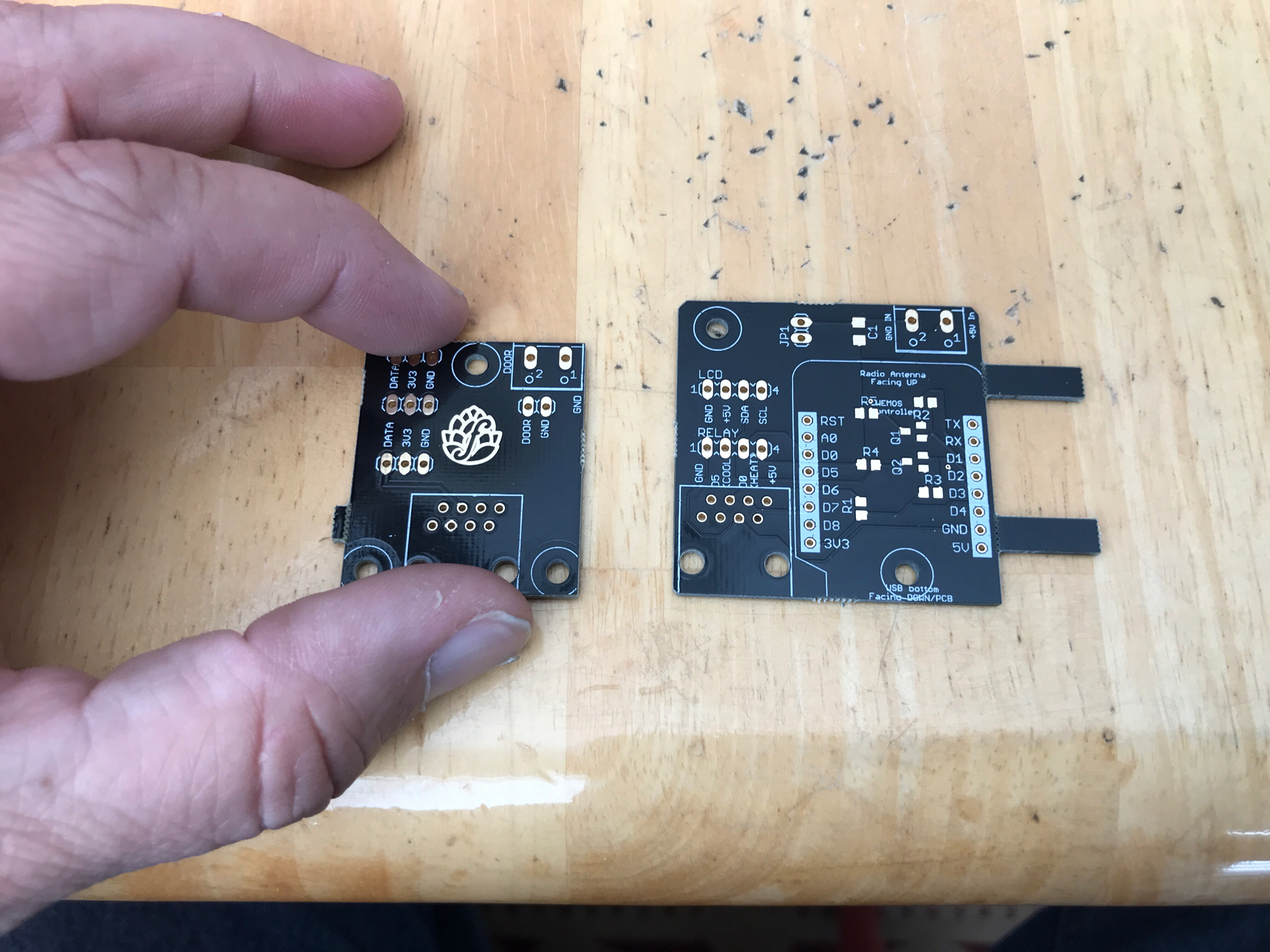
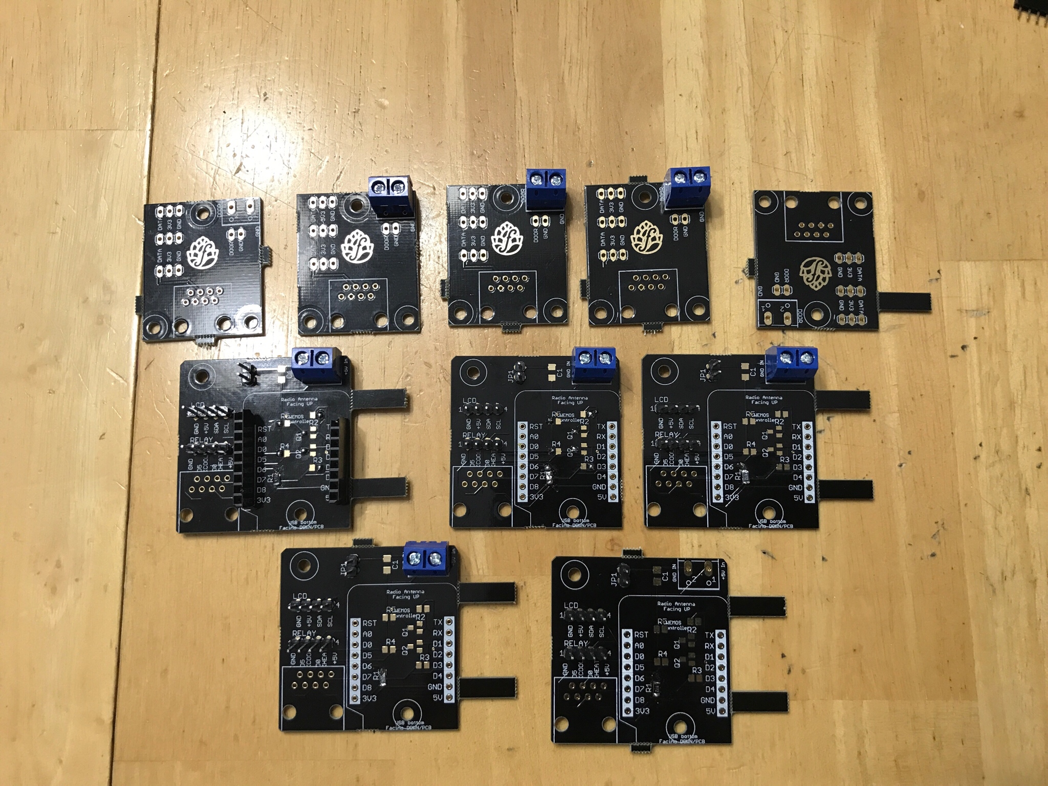
I found it a lot easier to solder on the SMD components first before anything else.
Hard to tell but are the Mosfets and resistors contacting both pads? Looks like they are soldered on one side of the pad and not completing the circuit.
Best trick I found was to use more flux than you think you need and move the smd around with a solder tool kitI’m still waiting on the mosfets and 10k resistors. Freaking China! I only put in the 4.7k resistors at R1, male pins, 5mm screws, and the pair of female pins....and practiced soldering.

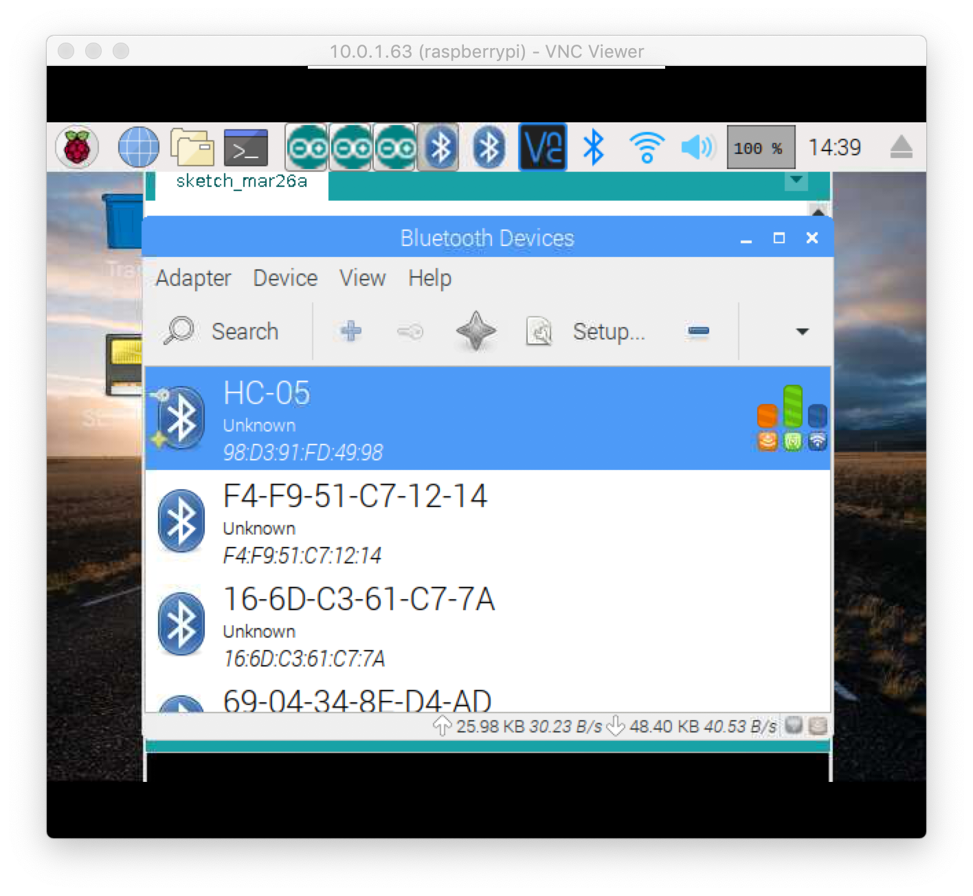
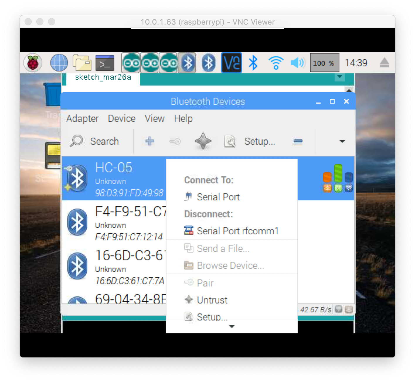
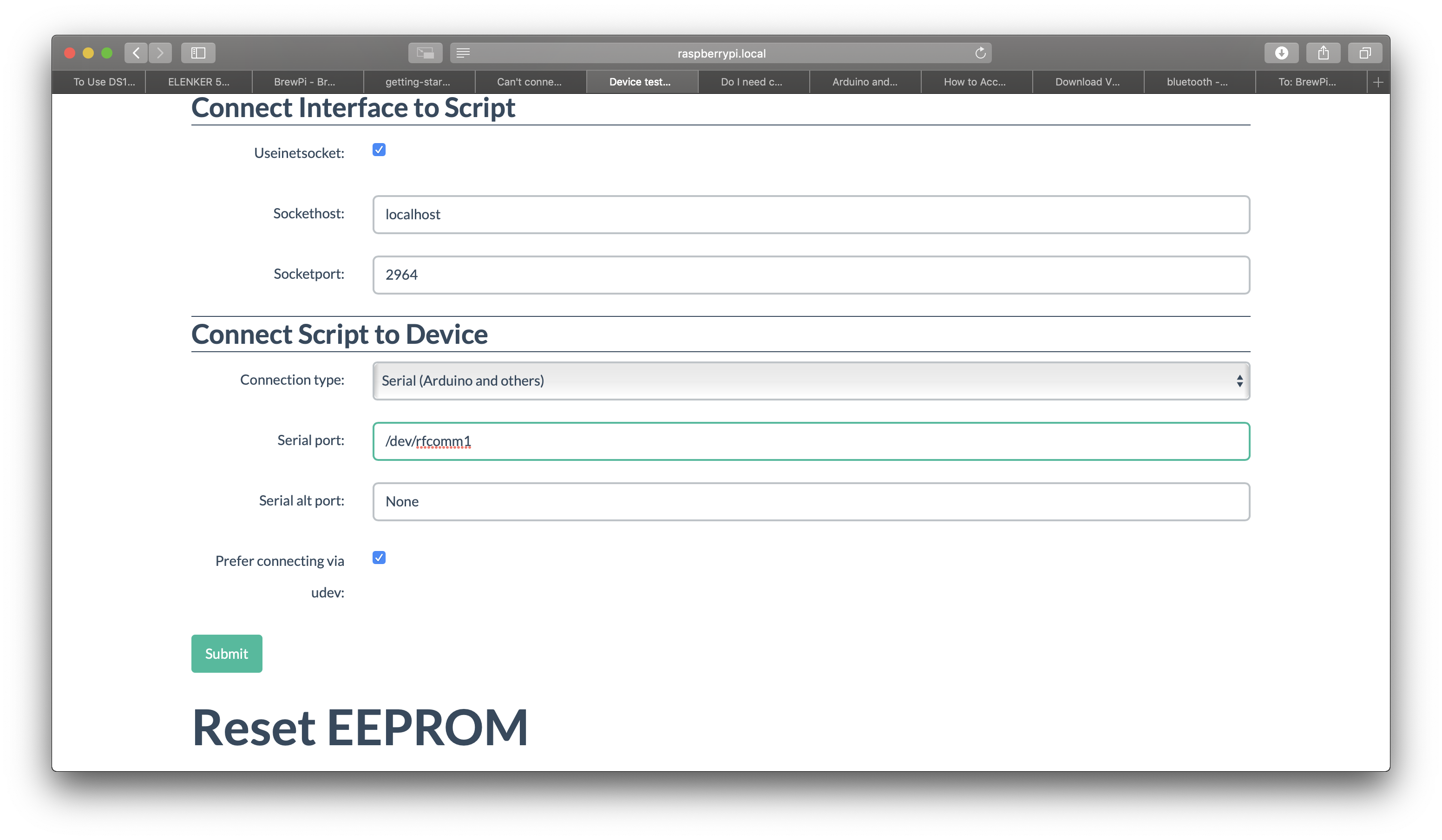
It isn’t likely related to your issue, but you’ll probably want to untick “prefer connecting via udev”.
Related to your issue, if you open a terminal and run this command what do you see?
ls -la /dev | grep rfcomm
Hm. Ok. That’s why /dev/rfcomm doesn’t work at least...That command doesn't seem to do anything I can see. Just returns to a new line with no text displayed.
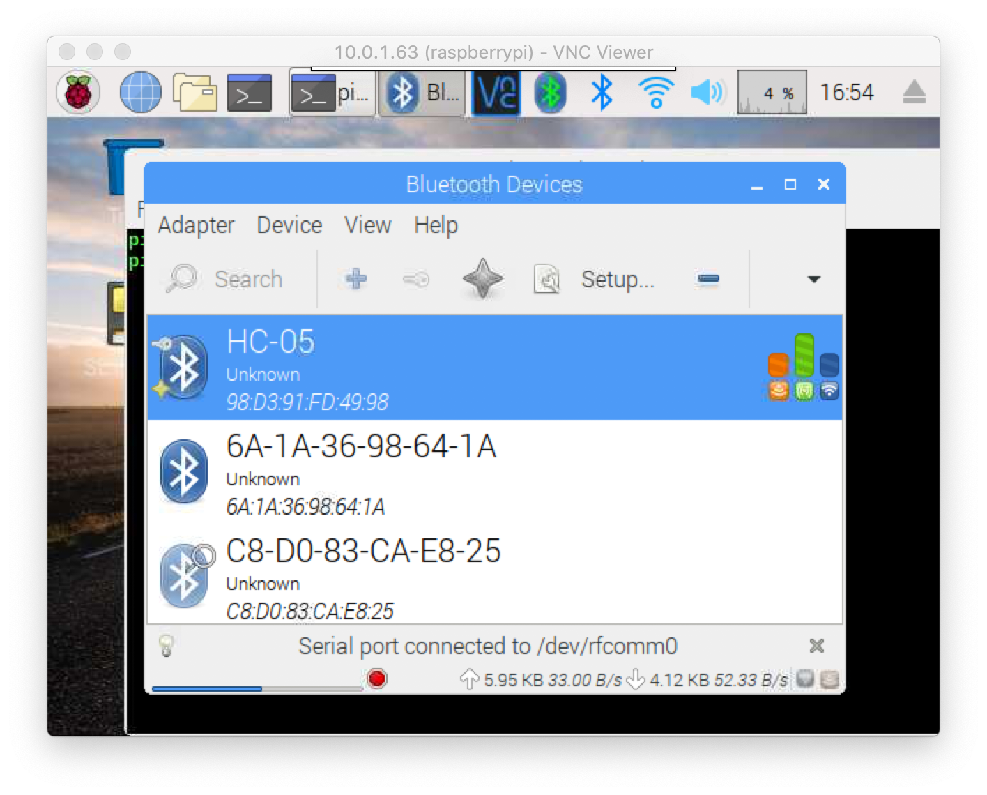
View attachment 619267 I selected a setting to connect to serial port, and now it says connected. Does this look right? Also, it says /dev/rfcomm0 now. I tried re-adding the controller with that instead of rfcomm1 and it still doesn't work.
Should I first flash the controller using the USB, then unplug and used advance set up with input of the serial port?
In line with @day_trippr 's note, if you recreate the device with serial port /dev/rfcomm0 then it should work. Just make sure you untick "prefer connecting via udev"
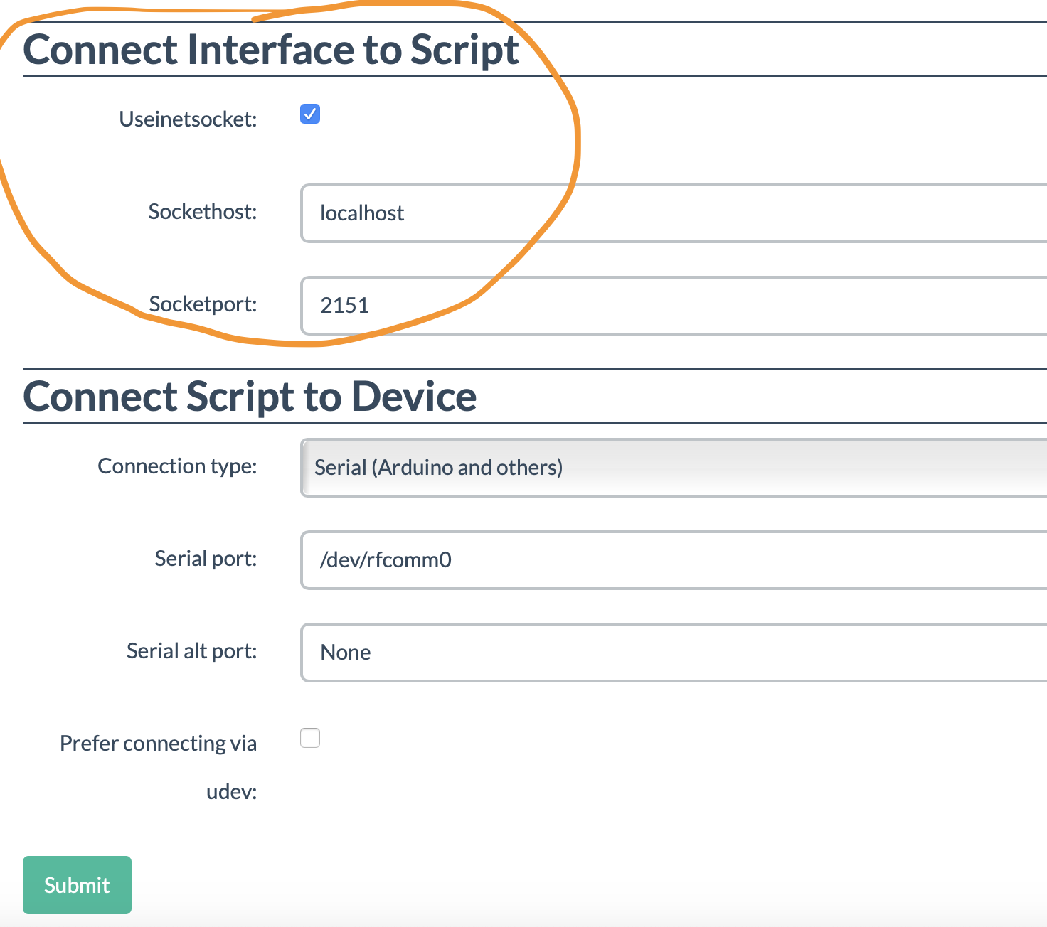
It's weird, every time I untick "prefer connecting via udev" and click Submit, when I leave the manage page and return it re-ticks it. It still keeps my input of the serial port as /dev/rfcomm0.
Also, is there anything I need to change in the "Connect Interface To Script" section?
View attachment 619340
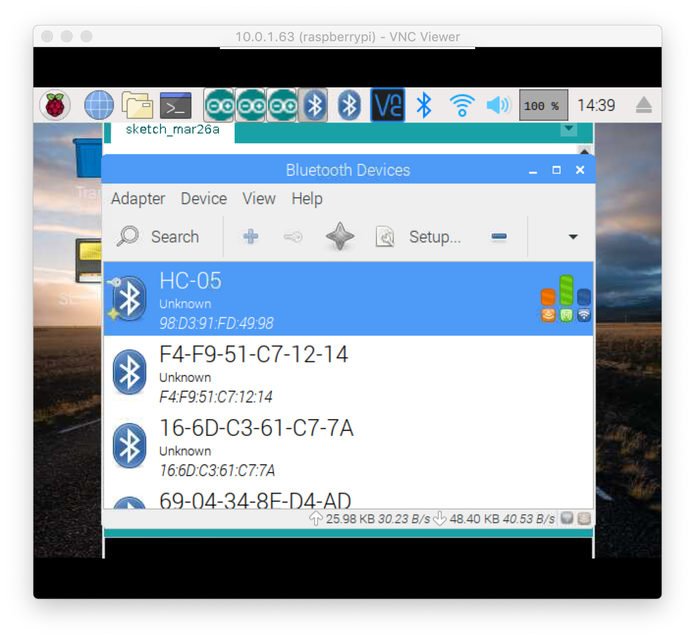
There are some differences in BT management in Stretch warranting some changes to @day_trippr's original instructions. I've put them here.
There are some differences in BT management in Stretch warranting some changes to @day_trippr's original instructions. I've put them here.
