• Please visit and share your knowledge at our sister communities:
  • If you have not, please join our official Homebrewing Facebook Group!

    Homebrewing Facebook Group

Fermentrack: Fermentation monitoring & BrewPi-www Replacement for Raspberry Pi

Homebrew Talk

Help Support Homebrew Talk:

This site may earn a commission from merchant affiliate links, including eBay, Amazon, and others.
Cheers @Thorrak,

Hey @rocketpants - glad you like it!
There currently is not any caching of which graph lines are enabled/disabled, unfortunately. This may come at a later date, however, as you’re not the first person to request it.

Would it be easier to set up an autoupdating chart option, or a button to reload the chart on demand (or repurpose double click to load the new chart data)? Then the visibility status of each line should be retained (I think). I've been playing round with dygraphs for a bit but am by no means an expert. full of ideas but not much help.
 
Cheers @Thorrak,


Would it be easier to set up an autoupdating chart option, or a button to reload the chart on demand (or repurpose double click to load the new chart data)? Then the visibility status of each line should be retained (I think). I've been playing round with dygraphs for a bit but am by no means an expert. full of ideas but not much help.

I honestly have no idea. DyGraphs has data streaming support, but it’s not something I’ve played with.
 
Hoping someone can help with my latest issue.

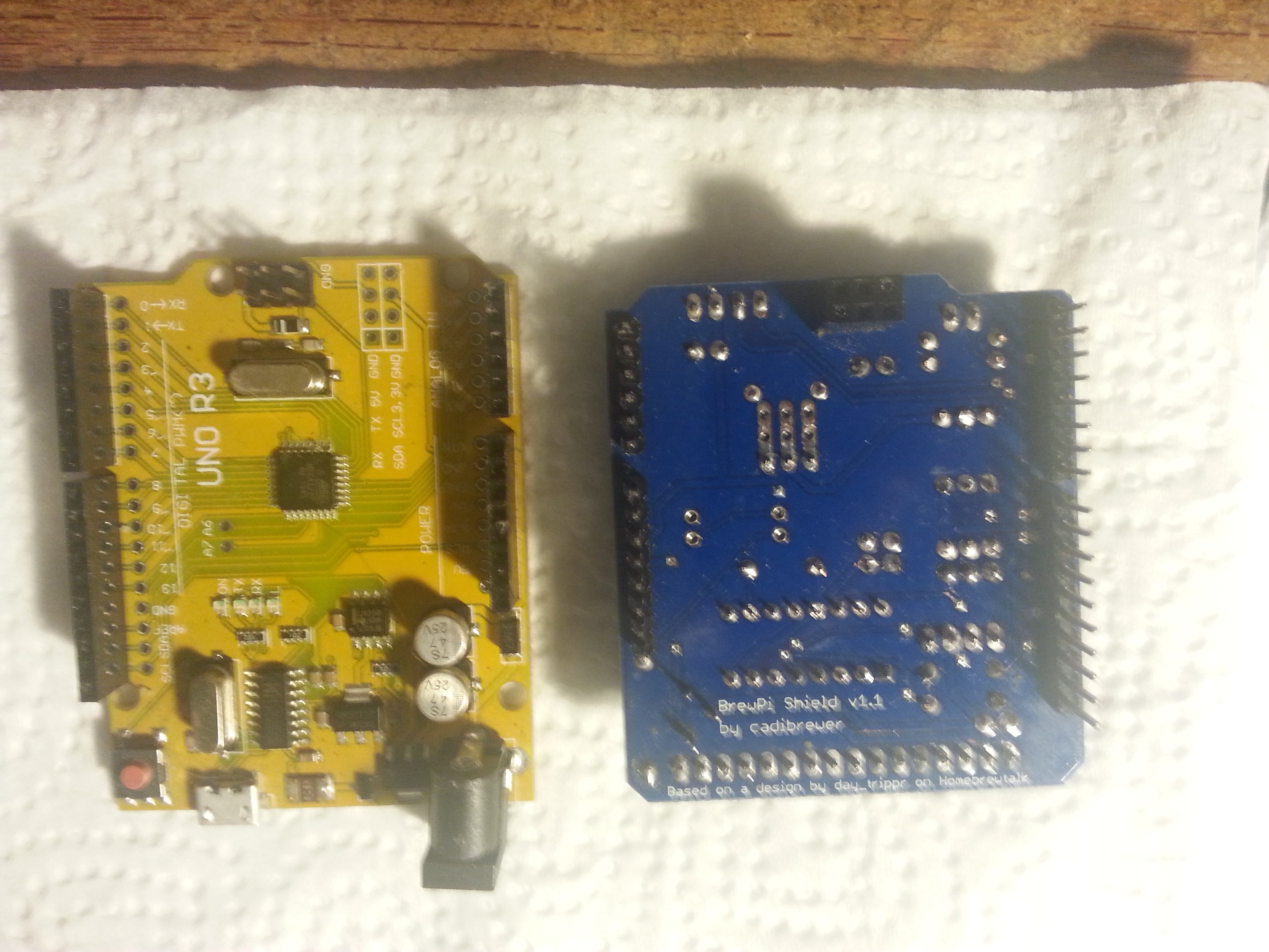
I built a DIY BrewPi shield for my arduino following this guide: https://diybrewpi.fandom.com/wiki/BrewPi_Shield

There are 16 headers at the bottom to connect a LCD module. I used this LCD: https://www.amazon.com/gp/product/B00GZ6GK7A/ref=oh_aui_search_asin_title?ie=UTF8&psc=1

I got everything hooked up, installed Fermentrack, flashed my Arduino successfully, and my Fermentrack page shows that it is receiving text from the controller, displaying Beer temps and Idle time, etc.

My LCD is backlit, and as I turn the trimmer with a screwdriver, the contrast appears to be adjusting (goes from solid blue to white blocks for each character space. However, no actual text. I soldered up another shield exactly to the guide above, thinking maybe I screwed up somewhere along the process - first time soldering :) - and same thing.

Any thoughts on things to try? Could it just be the LCD? I've seen failures with other people trying this, and mostly it would be garbled text, indicating a faulty LCD. But since mine has absolutely no text at all, I was thinking it was something else.

Thanks!
What is the version number of the shield you are using?

And can you post a picture of your shield soldered up?
 
Yes, Cadibrewer, says v1.1
 

Attachments

  • B4E05F0E-B3C6-4A13-8356-1EA7CA6E1E63.jpeg
    B4E05F0E-B3C6-4A13-8356-1EA7CA6E1E63.jpeg
    1.4 MB
  • D388172F-36A3-4D41-91DC-27B03E95FAE8.jpeg
    D388172F-36A3-4D41-91DC-27B03E95FAE8.jpeg
    1.7 MB
Right?? I'm just happy that your project and my shields are still useful to people.

The diywikia page he linked to is based on the first version of the shield. Other versions have a slightly different BOM, so there's a small chance that's causing his problem.

Others have run into the issue of not turning the trimmer screw enough, but if he's getting white blocks, that isn't the issue.

One early version of the shield had a bad silkscreen that transposed the pin numbers on the LCD header, causing that exact issue. But that version of the shield never made it into the wild...

A version number and a picture would help diagnose it.
 
Sorry, we were posting that last one at the same time.

I believe your problem is that you've left off the 3x2 header near the top of the board in your pictures. That is mainly for programming the UNO, but IIRC, I pulled the power to the IC chip from that pin in a separate power net in order to isolate the IC as much as possible to minimize screen scrambling issues.

Easy fix! You don't need the fancy 3x2 socket if you don't have one. Just use male header pins and solder them in from the top of the board with the small side of the pins sticking out of the top of the board. You should be good to go.
 
The corresponding 3x2 pins on the Arduino that match the location on the shield are male as well. This is where I was a bit confused when soldering it and left it out. Do they just need to make contact with eachother, or do I need to use female headers on the bottom of the shield instead?
 
The corresponding 3x2 pins on the Arduino that match the location on the shield are male as well. This is where I was a bit confused when soldering it and left it out. Do they just need to make contact with eachother, or do I need to use female headers on the bottom of the shield instead?
Female headers on the bottom of the shield will work.
 
No, sorry, I meant female headers. You don't need the special socket with the long male pins, but you do need female headers. The pins don't need to be long and stick out any further on the top than just regular headers. Sorry for the confusion.
 
I should write a nasty letter to that person for failing to credit and thank the person that actually designed the shield!
Sheesh!

Cheers! ;)
Instead of "based on a design by @day_trippr", should I have said, "stolen from @day_trippr and then forced him to review multiple bad designs and then tutor cadibrewer on the basics of electronic engineering and pcb design that even a middle school student could master"? That would have been more truthful! [emoji16]
 
lmao!
Wait - is that your web page? :D
[edit] Reviewed the sub-thread and I reckon it's some interloper. I should thrash him thoroughly from afar ;)

Cheers!
 
Last edited:
I think fuzze created the original page. I added the shield soldering how-to. I could have probably been a bit more obvious with giving due credit...
 
I think you're missing my gist: my nom de plume is there, but your name didn't appear with any credit on that page. Seems wrong.

Anyway, I do remember we split the 5V feeds to a "5V" and a "A5V", and it's the "A5V" that gets lost without the 2x3 - and that feeds the shift register and the backlight drive circuit...

Cheers!
 
I got your gist, but I don't feel like I deserve any credit, @day_trippr. All I did was realize my own limitations (a man has got to know his own limitations) and figured out that I could never solder up the prototype board successfully like you did. I ordered the board and when it arrived, it was soooooo much smaller than it looked in your pictures. So I learned how to create a pcb board. And then you redesigned my board twice to make it work. So really, I just conned you into doing what you should have done all along. Yay me!
 
Thank you to everyone involved in this long, crazy evolution of these DIY devices! Soldering the female headers to that 3x2 configuration worked! LCD is displaying text! I'm sure I did something else wrong somewhere, so i'll be back here for more questions. Just glad the makers are still checking the threads.
 
As I suspected, ran into another issue :confused:

I hooked up my temp probes to the shield, and connected my 2-channel relay board to the top of the shield, plugged it all in, and opened Fermentrack dash. I see a section on the site for configuring sensors and other devices, but I'm a bit confused as to how we determine which device is which. Even if i unplug all of these wires, it still shows the same "Available Devices" in the site. I've attached a screenshot. Since this shield has it's own headers for the temp probes and relay, meaning wires aren't plugged into the Arduino's numbered digital pin ports, I don't know how to properly set this up in Fermentrack when it displays those pin numbers. Also, is it even recognizing the probe or relay, since nothing changes when I unplug them and plug them back in?

It's hard to deceiver the Fermentrack documentation since it doesn't know I am using this custom shield.

Hoping one of y'all can give me a bit of a tutorial into configuring the probes and relay with this specific shield!
 
The pinout should be what's specified right above the pin list. Cadibrewer's board used standard pinouts for Arduino builds. ;)

You may need to experiment to see which relay is heat vs. cool, but that's just a labeling thing once you have them hooked up to outlets.
 
Yep, that ^

Plug everything in and then experiment a bit to see what is what. I put one of the probes into warm water so I can tell it from the others. When you figure one out, configure it and label it. Then find the next.

FWIW, the shield doesn't chang anything from a standard arduino build. Fermentrack detects the probes but all of the relays show up as devices whether they are connected or not. That's the way the original brewpi worked.
 
I guess my main confusion is what Fermentrack is displaying already as Available Devices as seen in that screenshot. When I unplug everything, those Devices still show, and when I add a probe, no new Devices appear.

Also, I tried assigning one of these Available Devices that were already showing just to experiment, and it gave me an error.

Think of it this way: You aren’t assigning functions to devices on your controller, you’re assigning functions to pins on the arduino. Even when the relays are disconnected, the pins are still there — hence why unplugging everything does nothing.

Temperature sensors not showing up is another issue, however. They should show up within several seconds of you connecting them — though you will have to refresh the “assign sensors” page to get them to appear. If they aren’t, double check the wiring for those and make sure you have the necessary resistors in place. It’s also possible you have parasitic OneWire temp sensors — I don’t have a test script for Arduinos to detect those, but @CadiBrewer or @day_trippr may know of one...
 
Is there a recommended temp sensor to work with this version of the Cadibrewer shield?

Also, should I have flashed the Arduino controller with the temp probes and relay plugged in? I just flashed it without anything, not sure if this causes any issues or not.
 
Just ordered the SMD/w LCD & RJ-45 PCB’s and the entire BoM to control 4 chambers...just have to wait on that Slow Boat from you know where.

I probably will have a ton of questions, but I’m willing to research those as they pop-up.

While I’m waiting for that boat, I have a couple of pretty fundamental questions that I just can’t find a tutorial on, or adequate pictures to help me come to a conclusion.

1. For the power coming into a box that holds multiple controllers. Can I bring power into the box through just 1 male power inlet and then split that off to 2 different 5V 2A PSU’s? (I really wanted to do 4-controllers in one box, but I figured the total Amp pull may not be good for one circuit)

2. This DS18B20 Probe to RJ-45 Connector has me perplexed. Is this as simple as taking 2 DS18B20 probes, twisting like wires together, wiring them into the proper RJ-45 Connector Slot, crimping, and then connecting to the RJ-45 jack on the PCB?

I know everyone says this, but honestly, thank you. I really can’t wait to get this project started.
 
Nope, flash the controller with nothing connected. You're good there.

The sensors are not different for any of the builds or shields. One wire, ds18b20 probes will work. There were some that ran in parasitic mode out there and they won't work. Run the script referenced a few posts back to make sure you don't have parasitic models.

You can also try resetting the EEPROM under the advanced settings.

Finally, check your wire colors. There are many different combinations out there. Make sure you are using the combo from your seller.
 
While I’m waiting for that boat, I have a couple of pretty fundamental questions that I just can’t find a tutorial on, or adequate pictures to help me come to a conclusion.

1. For the power coming into a box that holds multiple controllers. Can I bring power into the box through just 1 male power inlet and then split that off to 2 different 5V 2A PSU’s? (I really wanted to do 4-controllers in one box, but I figured the total Amp pull may not be good for one circuit)

Yeah - there shouldn't be any issues splitting a single power inlet to multiple 5v2a PSUs. (Honestly - you could probably even get away with using a single 5v2a PSU to power two controllers, so long as neither had LCDs)

2. This DS18B20 Probe to RJ-45 Connector has me perplexed. Is this as simple as taking 2 DS18B20 probes, twisting like wires together, wiring them into the proper RJ-45 Connector Slot, crimping, and then connecting to the RJ-45 jack on the PCB?

Apologies for any confusion! Taking a step back, there's two versions of the board - RJ-11 and RJ-45. Both boards are designed to be used with something that takes the single RJ-11/RJ-45 port and splits it out to several endpoints that can be used for multiple sensors - but you have options on what that something is.

In the case of the RJ-45 board, it's pretty much exclusively meant for use in conjunction this PCB design. The idea is that you build the "main" PCB, then use an ethernet cable to connect it to that secondary PCB I just linked. That secondary PCB then has the temperature sensors soldered to it.

For the RJ-11 board, you can do that same configuration using a similar PCB, or you can use old-school telephone line splitters. If you use the telephone line splitters, then yes - you would splice an RJ-11 end onto the DS18b20 probes similar to how you described.


My recommendation is - unless you like splicing wires together - to go with either the RJ-11 or RJ-45 "breakout" board. The reason I prefer the RJ-45 breakout board is that most people have extra ethernet cables lying around from old routers and the like which are guaranteed to be wired straight (as opposed to crossover). With RJ-11, I found there was a mix of straight & crossover cables out there - not ideal, as it makes debugging why your temperature sensors aren't working well difficult.
 
Are there any connection logs I can use for troubleshooting? Trying to figure out if my iSpindles aren't working, or if Fermentrack isn't processing them right. Would be helpful if there was a communication log I could look at to see if they are talking.
 
Grab the sketch (below), save it as an .ino file, and load that into the Arduino IDE, then use the IDE to burn the Arduino. You may have to install one or both libraries (find them via Google) as I don't remember if either/both come with the IDE kit.

Hook up one probe and see what the sketch thinks it is.
Note you'll probably need to add a pull-up resistor...

Cheers!


Code:
#include <OneWire.h>
#include <DallasTemperature.h>


#define ONE_WIRE_BUS 18
OneWire oneWire(ONE_WIRE_BUS);

// Pass our oneWire reference to Dallas Temperature.
DallasTemperature sensors(&oneWire);

void setup() {


Serial.begin(9600);

sensors.begin();
}

void loop() {

Serial.print("Parasiter is: ");
if (sensors.isParasitePowerMode())
Serial.println("ON\n");
else
Serial.println("OFF\n");

Serial.print ("Detected ");
Serial.print(sensors.getDeviceCount(), DEC);
Serial.print(" devices\n");

byte deviceAddress[8];

for (int i = 0; i < sensors.getDeviceCount(); i++) {
sensors.getAddress(deviceAddress, i);
Serial.print("Device
Serial.print(i);
Serial.print(" is a ");
switch (deviceAddress[0]){
case DS18S20MODEL:
Serial.print("DS18S20\n
break;
case DS18B20MODEL:
Serial.print("DS18B20\n
break;
case DS1822MODEL:
Serial.print("DS1822\n
break;
case DS1825MODEL:
Serial.print("DS1825\n
break;
default:
Serial.print("Unknown\n
}
}
delay(1000);


sensors.requestTemperatures(); // Send the command to get temperatures
delay(750);

for (int i = 0; i < sensors.getDeviceCount(); i++) {
float temp = sensors.getTempCByIndex(i);

Serial.print ("Sensor ");
Serial.print (i);
Serial.print (" ");
Serial.print(temp);
Serial.print("\n
}
Serial.print("\n

}
 
Are there any connection logs I can use for troubleshooting? Trying to figure out if my iSpindles aren't working, or if Fermentrack isn't processing them right. Would be helpful if there was a communication log I could look at to see if they are talking.

Sadly, there's not much to log with the iSpindel -- either it connects/works (and there's no need for a log) or it doesn't connect (and Fermentrack wouldn't know to log anything).

What issues are you experiencing? Is the iSpindel set up & configured to connect to Fermentrack? Can you post a screenshot of the iSpindel settings so we can take a look?
 
I can't provide any information that @day_trippr didn't already give. But I believe the OneWire and DallasTemperature libraries are included. If not, they are super easy to add. I think the Arduino IDE now has a library manager that you can use to add them.
 
Sadly, there's not much to log with the iSpindel -- either it connects/works (and there's no need for a log) or it doesn't connect (and Fermentrack wouldn't know to log anything).

What issues are you experiencing? Is the iSpindel set up & configured to connect to Fermentrack? Can you post a screenshot of the iSpindel settings so we can take a look?

Copy paste from the iSpindle thread :
Has anyone had luck using their iSpindle in a stainless conical? I worked up two of them and made it through testing /calibration with 7 strengths of sugar water with a 10 second refresh rate. Filled up my two half barrel brewtechs with the days brews, set them to a 30 minute refresh rate, and threw them in. From that point on, I've been unable to confirm any communication. My wireless AP is only about 15 feet away, through one wall and the fermenter wall. I know for certain that they were turned on, and the last readings I had showed 4.2+ volts when they were floating in sanitizer. Seems strange to me that they both died right after changing to 30 minute refresh rates and putting in the fermenter. The only thing I can assume is the stainless interfering but I've read several other people reporting no issues using them that way. Any thoughts?

I'm thinking it's an iSpindle issue, but was trying to look into all sides of it
 
I know for certain that they were turned on, and the last readings I had showed 4.2+ volts when they were floating in sanitizer. Seems strange to me that they both died right after changing to 30 minute refresh rates and putting in the fermenter. The only thing I can assume is the stainless interfering but I've read several other people reporting no issues using them that way. Any thoughts?

Hmm. So they were working before you closed up the Fermenter, but now aren't? Or are they working, but only infrequently?
 
Yeah - there shouldn't be any issues splitting a single power inlet to multiple 5v2a PSUs. (Honestly - you could probably even get away with using a single 5v2a PSU to power two controllers, so long as neither had LCDs)

No LCDs? Oh no! I need to make everything as difficult on myself as possible.

Apologies for any confusion!

Please, I take full responsibility for my confusion. No apologies needed.

Taking a step back, there's two versions of the board - RJ-11 and RJ-45. Both boards are designed to be used with something that takes the single RJ-11/RJ-45 port and splits it out to several endpoints that can be used for multiple sensors - but you have options on what that something is.

In the case of the RJ-45 board, it's pretty much exclusively meant for use in conjunction this PCB design. The idea is that you build the "main" PCB, then use an ethernet cable to connect it to that secondary PCB I just linked. That secondary PCB then has the temperature sensors soldered to it.

I definitely know I want to go the RJ-45 Route. I ordered your SMD w/LCD and RJ-45 PCB this morning. So, when it’s time...I will solder a RJ-45 Jack to the “main” board. I need to purchase the RJ-45 breakout board you just linked. When I receive it, I will solder an RJ-45 Jack on that too. I can also connect up to 3, in my case, 3Meter DS18B20, 3-wire probes to that breakout board. Using an Ethernet Cable, I connect the breakout board to the “main” board. Will the 4.7K resistor come into play for me? If so, where does that get soldered in?
 
Hmm. So they were working before you closed up the Fermenter, but now aren't? Or are they working, but only infrequently?

In Fermentrack, I got readings from both of them during the calibration process, and then put them in sanitizer to get ready for the batches. The last readings I have in Fermentrack are from them floating in the sanitizer. After switching to 30 minute update periods and putting in the fermenters, they've gone missing. I'm trying to not open them up and fish them out, but it's probably my only option at this point.
 

Latest posts

Back
Top