First off I would like to thank everyone that wrote in this thread. This has really been fundamental in helping me wrap my head around the whole electricity thing.
The diagrams and how they progressed were amazing in helping me through them.
I also want to thank you all for not do taking the "just do this" approach but instead approaching it from a "do it this way because" direction. I feel that is always way more advantageous way to get an idea across.
I'm working on a similar, minus the BCS but rather using PIDs.
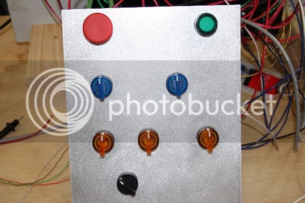
I want my panel to be Star Trek meets Binford Tools, if you get my drift
")
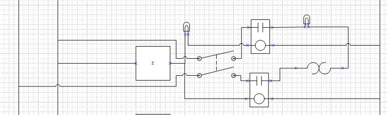
I'm hoping my diagram shows:
- The PID to be on when the unit has power regardless of element state
- The element to be able to turned off a switch on the panel
- Both legs of element to be properly relayed using PID
- Green lamp to light when element is live (switch is ON)
- Red lamp to light when element is hot (switch is ON and PID has element ON)
Here is the excerpt to that section...is it diagrammed correctly?


![Craft A Brew - Safale S-04 Dry Yeast - Fermentis - English Ale Dry Yeast - For English and American Ales and Hard Apple Ciders - Ingredients for Home Brewing - Beer Making Supplies - [1 Pack]](https://m.media-amazon.com/images/I/41fVGNh6JfL._SL500_.jpg)