Electric Question

Homebrew Talk - Beer, Wine, Mead, & Cider Brewing Discussion Forum

Help Support Homebrew Talk - Beer, Wine, Mead, & Cider Brewing Discussion Forum:

This site may earn a commission from merchant affiliate links, including eBay, Amazon, and others.
Damn it, No Ed, the suggestion regarding F1 was a half thought through bad idea. Ignore it :D

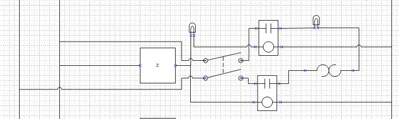
LOL... As you can see in the drawing, I did not implement it.

I got a bunch of SSRs and heat sinks from Auber yesterday :D
I should get the contactor today and finally be able to see how this may all fit.

Thinking about the actual panel... I have a 16" x 16" slant top console panel that I got from an HBT user for a great price. I hope all the stuff fits inside but, I'm afraid it is gonna look kinda bare with just 8 switches/buttons on the front. What do you think about a built in 8-track tape player?

Ed
 
...
I was back and forth in my original thoughts about having the e-stop kill power to the BCS... what are your thoughts?
You didn't ask me, but I'll chime in. ;)

If you are in the middle of a process and need to e-stop, if it kills power to the BCS, you would have to set it back up to continue. Granted, if you have to e-stop, it was probably a good reason and worrying about restarting the BCS may be the least of the worries. Still a toss-up in my opinion.

My case is different though. I will have the BCS mounted or sitting over near my fermentation cooler plugged into the wall. I will be using cat-5 cable to provide the 6 lines I need between my panel and the BCS: +5VDC, 0VDC, probe, probe GND, output0 (heater), output1 (pump).

I will have 2 RJ45 jacks on my panel box. One jack is for the probe(s) input. The other is for sending the signals to/from the BCS.
 
...
Thinking about the actual panel... I have a 16" x 16" slant top console panel that I got from an HBT user for a great price. I hope all the stuff fits inside but, I'm afraid it is gonna look kinda bare with just 8 switches/buttons on the front. What do you think about a built in 8-track tape player?

Haha, yea, I was thinking the same thing about my panel. Mine will only have 4 buttons/switches. I was going to try the 8x8x4 box, but I don't think I can get the 2 heater ssrs/heatsinks in there with everything else. Going to check out the 12x12x6... 4 buttons/switches on that one is really going to look bare. ;)

EDIT: Oh, I almost forgot! I got my BCS and probes in last night!
 
I think you should put a mini reel to reel. Tell people it is the hard drive for the BCS.

I LOVE IT... I have an old beer tap I might mount on it too.

Now, I'm thinking I should make it look like the inside of the ship on "Lost in Space" about 40 lights blinking randomly.
 
I LOVE IT... I have an old beer tap I might mount on it too.

Now, I'm thinking I should make it look like the inside of the ship on "Lost in Space" about 40 lights blinking randomly.

Hey Ed,
You could add some lights on the panel to indicate the status of your fuses/breakers. Just run a tap from right after the fuse through the light, then to N. If your lights are on, all your fuses are good. ;)

EDIT: in the case of the +5VDC fuse, you would go from the light to 0VDC
 
I installed the 50 amp GFCI breaker and receptacle today. The contactor I got from Ebay arrived and should work fine. The switches and some other stuff has been ordered.

I put the drawing on mediafire so you should be able to see the whole thing now.

http://www.mediafire.com/file/z21kmjnqnd0/Visio-Panel v5.0.pdf

I will keep this thread updated with progress related to the electrical and control situation.

I stated another thread if you are interested in where I am with plumbing... of course I'm looking for input ;)

Here's the link;

https://www.homebrewtalk.com/f51/brewery-plumbing-questions-158618/

Thanks,
Ed
 
I've been reading this thread for awhile, and am starting to understand what it going on.
I did have a question. Back in #50 and #51 you were talking about which contactor to use as part of the e-stop stuff.
The contactor that was listed there had a 220V coil, which, if I understand correctly means that you need 220V to the coil in order to allow the 220 through to the rest of the system (need help with the terminology here).
But in Ohio-Ed's last diagram, it looks as though there would only be 110 running through that part of the circuit (the circle part of the contactor diagram).
I'm sure I'm missing something - so I guess I'm just looking for some clarification.

I'm way off from starting this project ($$), but am trying to understand everything I can.

Thanks,
Eric

Eric,
The contactor is a double pole contactor (relay) so it can SWITCH both legs of the 220 supply.

The round part of the symbol in the diagram is a magnetic coil which makes or breaks the relay contacts depending on if energy is applied. The drawing indicates this contactor to use a 120v coil (I don't remember mentioning a 220v coil). So, when 120 volts is applied to the coil, the contacts will close, and power will flow to the rest of the system.

Hope this helps...

Ed
 
Maybe you are using a different contactor than the one you were talking about then. Here's the link to that contactor.


Here is CodeRage's response to that contactor


I guess my main problem is understanding how to read what a contactors inputs and output are voltage-wise.

Eric

Gotcha... I do remember that contactor now. And, nope, that is not the one I ended up with. I found one that has a 120v coil. The control, or coil, voltage depends on your design and is completely different than the contact voltage. I agree, reading ebay listings and specs can be a bit confusing if you are like me and not familar with the industy jargon. I ended up finding one that had the words in way I could understand.

Ed
 
I guess my main problem is understanding how to read what a contactors inputs and output are voltage-wise.

Eric

For the E-stop circuit demonstrated above, you need to find a contactor with a 120VAC coil. You can make it work with a 240VAC coil but it will require a triple pole relay.

The rating you need to be concerned with is the Resistive Amp rating. It needs to be equal or greater than the service providing it power. You won't exceed the contact's voltage rating with 240V split phase.
 
So I was understanding mostly.
Does the load part matter. i.e. do I need to specifically look for a contactor with a 120V coil that will allow 240V through?

I think I understood the part about the Resistive Amps - just the contactor that was listed and comparing it with the diagram was confusing me.

Ohio-Ed, do you plan on publishing a parts list for your build?
 
So I was understanding mostly.
Does the load part matter. i.e. do I need to specifically look for a contactor with a 120V coil that will allow 240V through?

Nah, the coil voltage is independent of the contact voltage. You could use one with a 24VDC coil to switch 240VAC if you were so inclined.

If you are running a 50A circuit or or less, Auber instruments has what you need ($13 for 50A and $9 for 30A)
 
So I was understanding mostly.
Does the load part matter. i.e. do I need to specifically look for a contactor with a 120V coil that will allow 240V through?

I think I understood the part about the Resistive Amps - just the contactor that was listed and comparing it with the diagram was confusing me.

Ohio-Ed, do you plan on publishing a parts list for your build?

I might but it will likely be awhile... I have bought a $hit load of stuff because I thought I might use it, and may not. I'll have to inventory what I actually use vs what I bought.

I got the contactor from Ebay for $.99.

Turns out the one I got is probably bigger that needed. I would get the one CodeRage mentioned from Auber if I had it to do over.

Ed
 
Yeah, that's it.

As long as you aren't using solid core wire, crimp terminals are recommended. Forks or rings would work. I tried to use the blade type connectors and was not impressed, the vibration from engaging the coil caused them to loosen up over time.
 
thanks for all the help. I'm working on getting a full parts list, then I'll probably start a new thread to make sure I have it all together.
 
First panel layout, what do you think?


The box is a slant top 16" x 16".

Basically, the box is about 2" high in the front and about 11" high in the back.
The heat sinks will be on the back.
Probe connectors will be on the back, below heat sinks.
220 supply will come in from the bottom (back right corner).
Twistlocs for the elements will be on the bottom (in the back)
Outlets for Pumps will be on the bottom (in the back)
Network jack will be on the left side toward the front.

Ed

View attachment Visio-Panel Layout v1.0.pdf
 
First panel layout, what do you think?

Move the pump switches to the 3rd row (from top) and space out the heater switches across the 2nd row (putting the HLT/BK select between the HLT and BK switches).

Just a suggestion. Doesn't hurt to move them around and see what it looks like. :D

EDIT: could you post your visio file too, please?
 
Any reason the HLT/BK Select switch is so close to the row above?

I am guessing that it is because that switch determines which of the two are active. Makes sense to me.

Following that methodology I would put the HLT pump controls above the HLT HOA and the second pump above and between the BK and the RIMS. May make it look a little clustered in one spot though.
 
I am guessing that it is because that switch determines which of the two are active. Makes sense to me.

Following that methodology I would put the HLT pump controls above the HLT HOA and the second pump above and between the BK and the RIMS. May make it look a little clustered in one spot though.


I understand your point of arranging the switches in a way to similar to their relationship to the vessels and use. Problem is the Heat Element Switches can't be in the same order as the vessels. The HLT & BK switches need to be next to each other to make the HLT/BK selector make sense.

I moved them around a few times but haven't really found an orientation that really jumps out at me... The problem is that both pumps interact with two of the three vessels.

Pickles - As CodeRage said, my intention is to use the HLT and BK labels as the selector choices for the HLT/BK Selector switch. I may move it down a bit, but I want it to be obvious that is selects between the two switches above.

Ken - I'm trying to conserve some real estate on the panel in case I find something else to add... When I bought this panel, I thought I'd have all the switches, three PIDs and a timer. I really like the AMP meter that Kal put on his panel, just not sure I'll find space inside for a power supply. I can't load the visio file here on HBT, I'll try to load it on a share site and provide a link when I get a chance.

What do you guys think about the orientation and location of the Stop and Start buttons? What about the wording on the labels of all the switches?
 
Well, you could group the pumps by where they draw from. Pump 1 will always draw from the HLT while pump 2 can draw from either the MLT or BK. I swapped the stop start buttons around and put some more space between them. So you don't accidentally bump the e-stop or the start button when trying to press one or the other.

OhioED-CP.jpg
 
Well, you could group the pumps by where they draw from. Pump 1 will always draw from the HLT while pump 2 can draw from either the MLT or BK. I swapped the stop start buttons around and put some more space between them. So you don't accidentally bump the e-stop or the start button when trying to press one or the other.

Very nice.
I could also label the pumps based on their input "HLT Pump" and "MLT/BK Pump".
Any reason you swapped the Start & Stop buttons? Is there a standard? I'm right handed, so I'm thinking I have to reach across the Stop button to hit the Start button. Also seems that the Stop button should be in one of the upper corners of the panel... so you can find it even from the back side.

Thanks for the input.

Ed
 
No problem at all. I just swapped the buttons cause thats how I am used to seeing them. By all means arrange them so the estop is easily accessible.

Now if you have a lot of room on your panel surface. You could put a large P&ID (Piping and Instrumentation Diagram) And place your switches and controls in their corresponding locations. Basically explode your plumbing diagram. The HLT/BK select will Look a little out of place but I am sure you can figure out a good spot for it.
 
You could put a large P&ID (Piping and Instrumentation Diagram) And place your switches and controls in their corresponding locations. Basically explode your plumbing diagram. The HLT/BK select will Look a little out of place but I am sure you can figure out a good spot for it.

Or do the diagram and put LEDs in place of every device and have them turn on during respective processes throughout the brew. I'm planning on doing this on the bottom of my panel.
 
Very nice.
I could also label the pumps based on their input "HLT Pump" and "MLT/BK Pump".
Any reason you swapped the Start & Stop buttons? Is there a standard? I'm right handed, so I'm thinking I have to reach across the Stop button to hit the Start button. Also seems that the Stop button should be in one of the upper corners of the panel... so you can find it even from the back side.

Thanks for the input.

Ed

I would mount the panic stop button to the top of the panel for easy access from any angle within arms reach working around your brewery. All other controls on the panel front cover or door. My take on this.
 
First off I would like to thank everyone that wrote in this thread. This has really been fundamental in helping me wrap my head around the whole electricity thing.

The diagrams and how they progressed were amazing in helping me through them.

I also want to thank you all for not do taking the "just do this" approach but instead approaching it from a "do it this way because" direction. I feel that is always way more advantageous way to get an idea across.

I'm working on a similar, minus the BCS but rather using PIDs.
I want my panel to be Star Trek meets Binford Tools, if you get my drift ;)

I'm hoping my diagram shows:
  • The PID to be on when the unit has power regardless of element state
  • The element to be able to turned off a switch on the panel
  • Both legs of element to be properly relayed using PID
  • Green lamp to light when element is live (switch is ON)
  • Red lamp to light when element is hot (switch is ON and PID has element ON)

Here is the excerpt to that section...is it diagrammed correctly?
Element1.jpg
 
Stupid little suggestion.
I would change "hand" on the Hand/Off?Auto switches to Manual, or just Man.
More Industry appropriate I guess.
 
First off I would like to thank everyone that wrote in this thread. This has really been fundamental in helping me wrap my head around the whole electricity thing.

The diagrams and how they progressed were amazing in helping me through them.

I also want to thank you all for not do taking the "just do this" approach but instead approaching it from a "do it this way because" direction. I feel that is always way more advantageous way to get an idea across.

I'm working on a similar, minus the BCS but rather using PIDs.
I want my panel to be Star Trek meets Binford Tools, if you get my drift ;)

I'm hoping my diagram shows:
  • The PID to be on when the unit has power regardless of element state
  • The element to be able to turned off a switch on the panel
  • Both legs of element to be properly relayed using PID
  • Green lamp to light when element is live (switch is ON)
  • Red lamp to light when element is hot (switch is ON and PID has element ON)

Here is the excerpt to that section...is it diagrammed correctly?
Element1.jpg


1.) Not sure if you really want an indicator in series with the control input on the upper SSR?

2.) Depending on the current you are switching, the DPDT switch you have on the AC side of the SSR's might be hard to find and expensive.
 
Stupid little suggestion.
I would change "hand" on the Hand/Off?Auto switches to Manual, or just Man.
More Industry appropriate I guess.

Industry standard is Hand Off Auto, Hand and Off positions are both Manual controls.

The indicators need to be tied between 110 and N or if they are 240V between L1 and L2. So come off of the load side of the ssr and tie it to the indicator. Then run the other side of the indicator straight to neutral (or other leg of 240).
 
I got ya...stick the Lamp on the switched wire...good catch didn't see that.

While I was typing this that placement (on the control side) on yours TOTALLY became clear...I think
On yours...If the switch is off the relay would sever the power to the element as that is what it is suppose to do anyway right?

So this should fix the switch issue...and the the lamp issue right?

(On the switch I figure to add a second contact block to it so when the switch is ON it will both complete the circuit to the light regardless if the PID is activating the element and allow the PID to reach the relays; I'm just not sure how to show two circuits on the one switch...that make sense?)

Element1v3.jpg


I actually finished the drawing itself (minus labels...damn need to do that)

If you wouldn't mind taking a look at it and seeing if I'm completely off the farm :mug:

View attachment eHERMSv2.pdf
 
Referring to Visio-Panel v5.0:
The S1LED, which is the lamp on the HOA switch for heater1, is directly connected to SSR2 and to N. What gauge wire will you be using for that? I'll be using 10 AWG wire to/from the SSR and to the heater, and it looks like without a separate fuse, I'll need to use 10 AWG for the lamp too, correct? Actually, this applies to all of your heater elements (I only have 1 though).

Thanks.

I'm gonna be cheatin a bit... I do not plan to put fuses in line to the LEDs. I'm planning to run 14 awg (because I have it) which is the maximum wire size spec'd for the connectors anyway. So I guess the LEDs will be acting as fuses. Even if you could get 10awg wire in the connectors, the switch is only rated for 10 amps anyway I think.

Good luck,

Ed
 
I got ya...stick the Lamp on the switched wire...good catch didn't see that.

While I was typing this that placement (on the control side) on yours TOTALLY became clear...I think
On yours...If the switch is off the relay would sever the power to the element as that is what it is suppose to do anyway right?

So this should fix the switch issue...and the the lamp issue right?

(On the switch I figure to add a second contact block to it so when the switch is ON it will both complete the circuit to the light regardless if the PID is activating the element and allow the PID to reach the relays; I'm just not sure how to show two circuits on the one switch...that make sense?)

Element1v3.jpg


I actually finished the drawing itself (minus labels...damn need to do that)

If you wouldn't mind taking a look at it and seeing if I'm completely off the farm :mug:

What is the control voltage of your SSRs? Looks like you have them wired for 120v.

Also I'm confused about why you have 2 lines connected to the pole of the switch on the bottom element (you really need labels so it is easier to refer to components). And both leds are gonna light at the same time on the bottom element.

And you still have LED1 in series with the contacts on R1 and the contactor.

Hang in there... you'll get it.
 
Thanks for catching the SSR mess...but I think I fixed that now.
You were right, I had them off the 110 main not the 12v
Labeling and touching it up I caught some issues too...but I think I finally have the LED mess sorted out so the elements have two lights on them...one when they are "ON" and one when the PIDs tell them to "Heat"

I also decided that since I want to use both the BK and HLT at the same time...I'd need to loose a BK element. And I think I can keep it under 48 amps too...so I'm looking at a 60amp service I guess.

I still have to do AWG and fuses...but I think I'm close now.


Started looking at some parts...and the question arises, if I needed a 60a 2-Pole 120v contactor for the e-stop, would a 63a 3-Pole 120v contactor work in its place leaving the 3rd pole empty?

(Sorry I had to zip it...but at 53kb its too big for uploading now)
(I think the "Legend" on the side is beefing up the size)

View attachment eHERMSv4.zip
 
Thanks for catching the SSR mess...but I think I fixed that now.
You were right, I had them off the 110 main not the 12v
Labeling and touching it up I caught some issues too...but I think I finally have the LED mess sorted out so the elements have two lights on them...one when they are "ON" and one when the PIDs tell them to "Heat"

I also decided that since I want to use both the BK and HLT at the same time...I'd need to loose a BK element. And I think I can keep it under 48 amps too...so I'm looking at a 60amp service I guess.

I still have to do AWG and fuses...but I think I'm close now.


Started looking at some parts...and the question arises, if I needed a 60a 2-Pole 120v contactor for the e-stop, would a 63a 3-Pole 120v contactor work in its place leaving the 3rd pole empty?

(Sorry I had to zip it...but at 53kb its too big for uploading now)
(I think the "Legend" on the side is beefing up the size)

I haven't looked at the drawing yet... but...
You might want to think REAL hard about going to a 60amp supply. Parts start getting real expensive real fast... That is where I started and I was looking at $100 each for a plug and receptacle just to plug it in, then if you go with 4/4 SO cord, you are looking at $6-8/foot.

An alternative might be to use a smaller element in the HLT? You could always heat your strike water in the BK (with the larger element) and transfer to the HLT to maintain the temp. If you don't plan to do step infusion mashes you shouldn't need to quickly change your sparge temps?

As for the contactor... the one I am using is a 3 pole. Make sure the coil is 120 volts. I got mine off ebay, it was a new unit and nobody bid on it... I got it for 99 cents.

Ed
 
My latest files attached... sorry the PDF's are too big so I had to ZIP them.

Panel v5.1 is the latest logic diagram, just added some color to distinguish the circuits.

The other file... Visio-Panel v5.1 Wiring v1.5, is the actual wiring diagram I am working to. I am in the process of wiring this on a temporary backplane (plywood) before I punch holes in my enclosure.

I currently have all the power lines in place up to the fuses / breakers. I did "really temporarily" wire the e-stop and start just to test out the contactor and applied power. And guess what... NO SMOKE!!!

I've been pretty busy, but I'll try to get some pictures of the temporary setup this weekend.

Ed

View attachment Visio-Panel v5.1 Wiring v1.5.zip

View attachment Visio-Panel v5.1.zip
 

Latest posts

Back
Top