You are using an out of date browser. It may not display this or other websites correctly.
You should upgrade or use an alternative browser.
You should upgrade or use an alternative browser.
DYI fermentation chamber
- Thread starter bruce_the_loon
- Start date

Help Support Homebrew Talk:
This site may earn a commission from merchant affiliate
links, including eBay, Amazon, and others.
bruce_the_loon
Well-Known Member
This is amazing!
How are you measuring specific gravity?
I have a Tilt bluetooth hydrometer and a RaspberryPI with a Python script called PyTilt which was modified slightly to log the temp and specific gravity to a time series database called InfluxDB and then use Grafana to plot the graphs as captured about.
https://github.com/atlefren/pytilthttps://grafana.com/https://www.influxdata.com/products/influxdb-overview/
Tilt bluetooth hydrometer
Cool, thanks for the tips. I would love to turn my rasberry pi into a historian.
A bluetooth hydrometer is about the raddest thing ever.
bruce_the_loon
Well-Known Member
Nog 'n update (translated Yet another update)
Sorted out a few small things this day.
Installed the drain lines for the condensation traps in both chiller boxes, need to find a suitable collection box to catch the effluent; finished securing more of the wiring harness and designed some Perspex spacers to keep the upper chiller coil from vibrating when running.
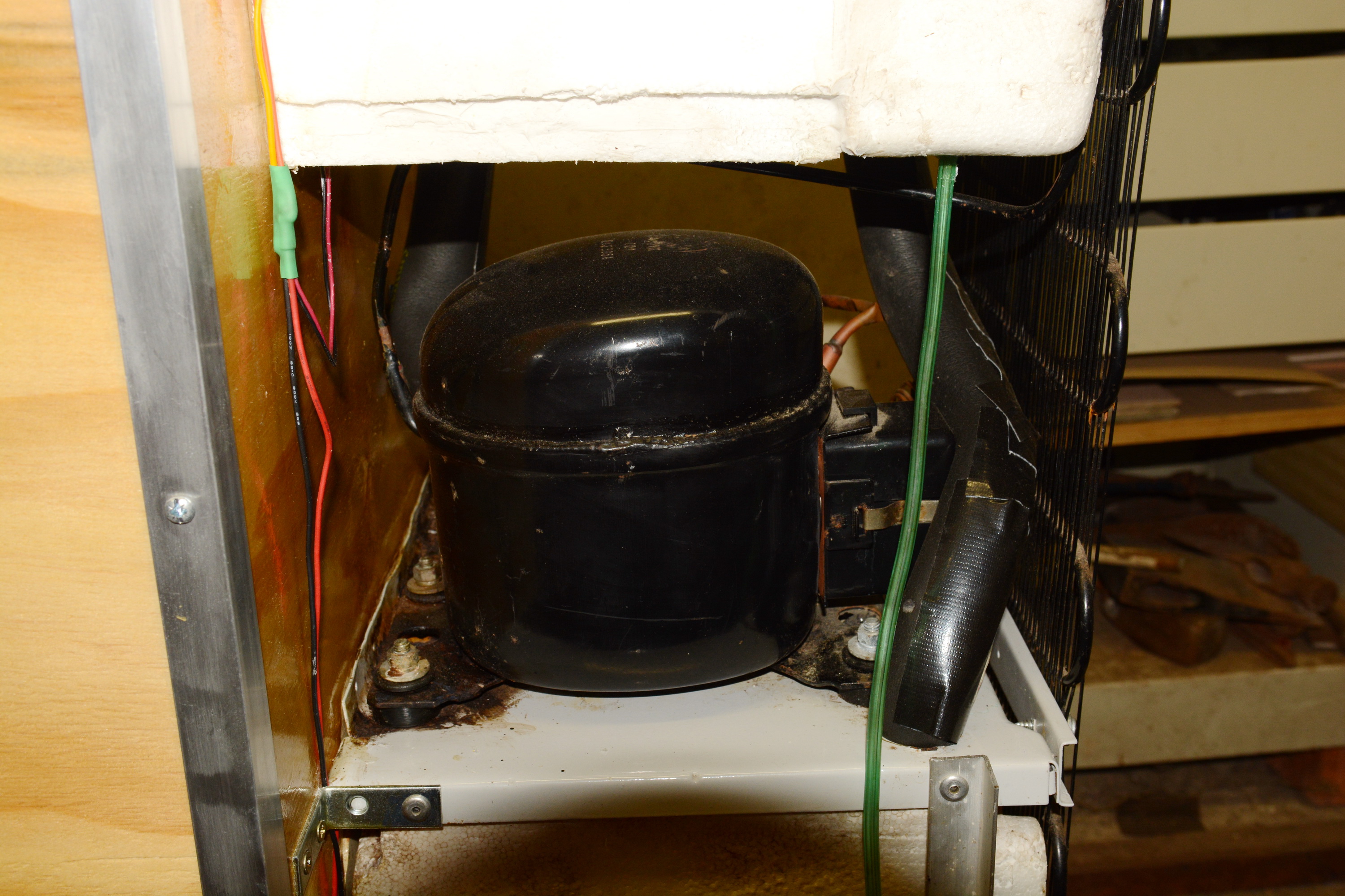
Photo 63 - Upper chiller drain line glued in place.
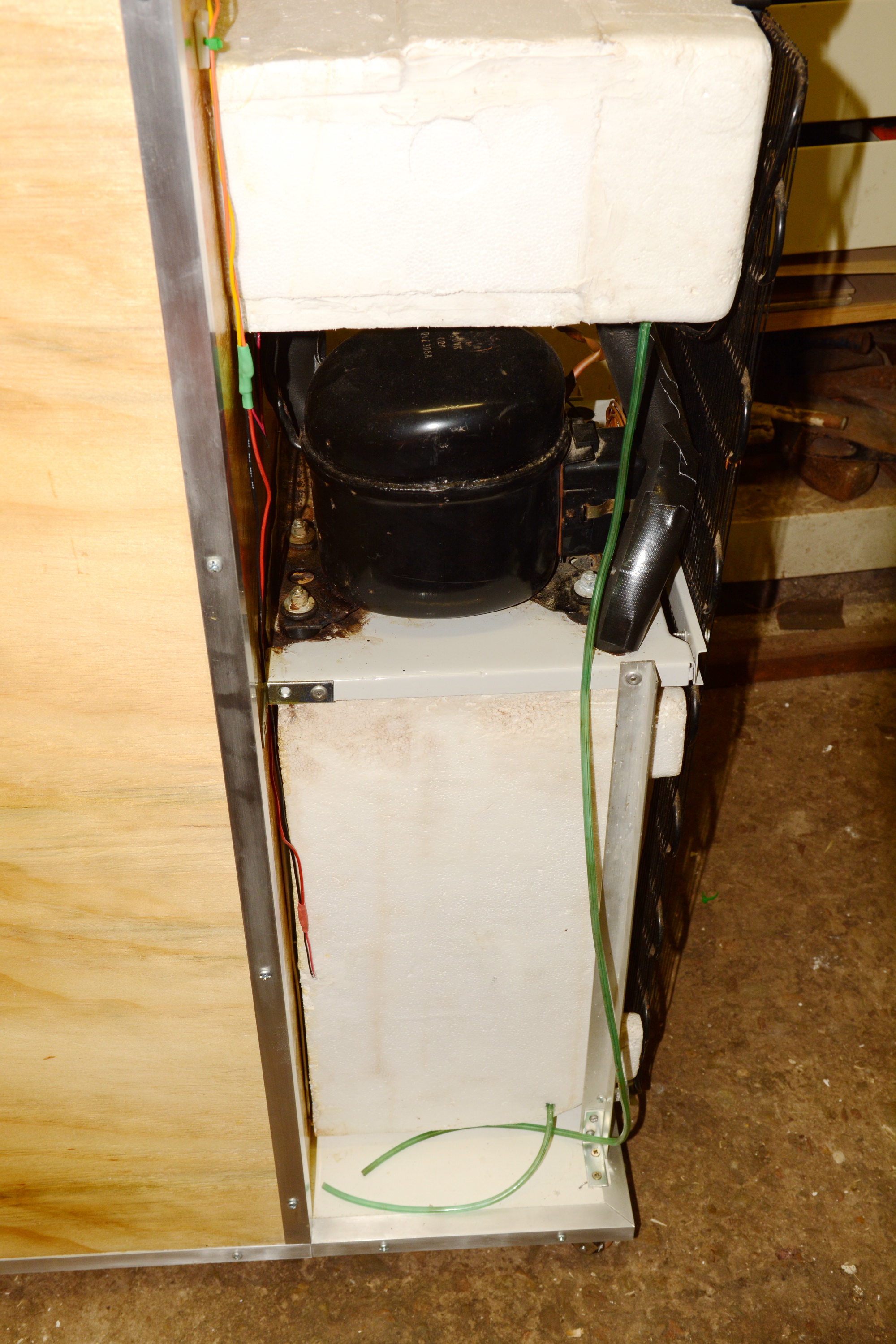
Photo 64 - Full view of both drain lines ending where the collection tank will be located.
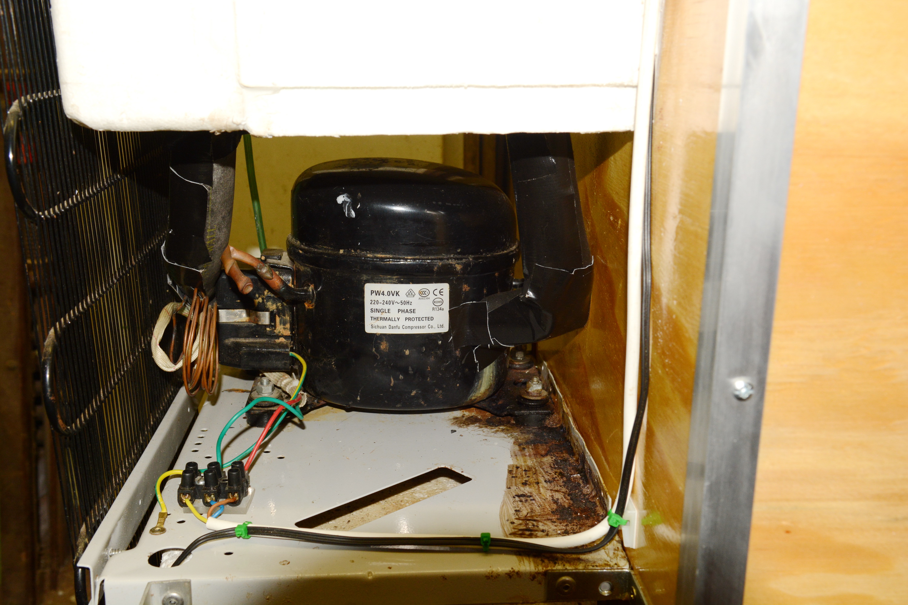
Photo 65 - Secured wiring and new cold circuit insulation in place.

Photo 66 - Two of the three Perspex spacers made to keep the coil from rattling against itself.
Still waiting for the Amazon package, somewhere in Dubai at the last tracking point.
Sorted out a few small things this day.
Installed the drain lines for the condensation traps in both chiller boxes, need to find a suitable collection box to catch the effluent; finished securing more of the wiring harness and designed some Perspex spacers to keep the upper chiller coil from vibrating when running.

Photo 63 - Upper chiller drain line glued in place.

Photo 64 - Full view of both drain lines ending where the collection tank will be located.

Photo 65 - Secured wiring and new cold circuit insulation in place.

Photo 66 - Two of the three Perspex spacers made to keep the coil from rattling against itself.
Still waiting for the Amazon package, somewhere in Dubai at the last tracking point.
bruce_the_loon
Well-Known Member
Spent some time fabricating the blower fan mounting bracket from some aluminium angle, couple of steel brackets and the last remaining salvaged channel bar from the water cooler. Either I've lost the bottle of 4mm x 8mm rivets or I used them up during this project. So the brackets that barely carry any load had to be assembled with 5mm rivets.
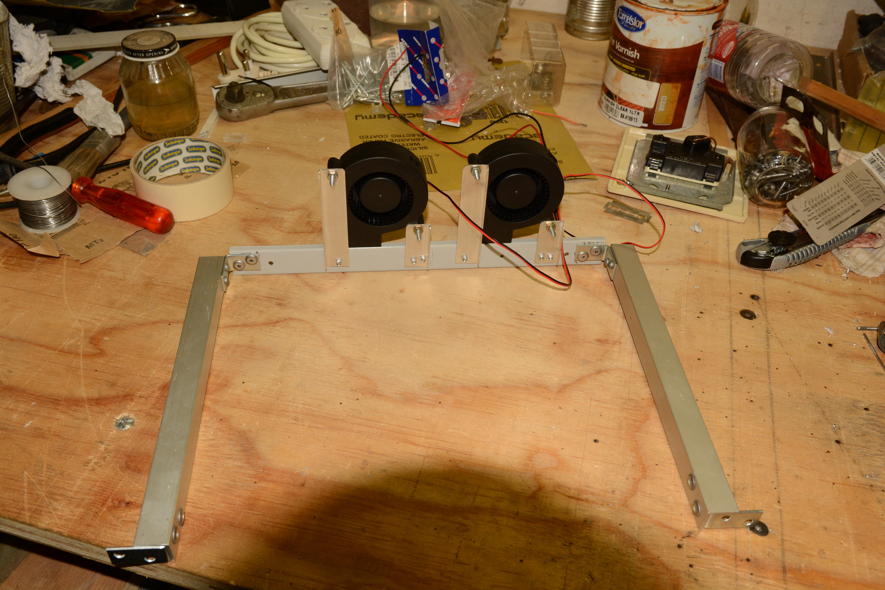
Photo 67 - Assembled blower fan bracket with fans mounted and ready to be fitted to the chamber.

Photo 68 - Blower fan bracket mounted to the chamber.
Starting to run out of things to do. Most of the structural work is done and just the closing side panels are waiting. The wiring harness for the blower fans needs to be extended and I need another couple of those cable-tie mounts to finish the harness completely. Time to raid another server accessories packet at work.
The perspex brackets on the upper chiller coil eliminated the vibration I was hearing, but introduced another buzz. Placed a strategic block of EPS between the side of the coil that floated free and the floor and that eliminated all extraneous sounds. To do - Reshape and glue the EPS block in place.
The full Mangrove Jacks SS fermenter left a discernible compression ring in the EPS floor of the chamber. Either a ceramic floor tile or a sheet of rigid plastic on top of the EPS will preserve the floor.
Considering a deflector panel to bounce the cold air from the upper chiller chamber down onto the fermenter, a bit concerned that the cold air just circulates above the fermenter as there is a large open space. A deflector panel would ensure it gets into the right area.

Photo 67 - Assembled blower fan bracket with fans mounted and ready to be fitted to the chamber.

Photo 68 - Blower fan bracket mounted to the chamber.
Starting to run out of things to do. Most of the structural work is done and just the closing side panels are waiting. The wiring harness for the blower fans needs to be extended and I need another couple of those cable-tie mounts to finish the harness completely. Time to raid another server accessories packet at work.
The perspex brackets on the upper chiller coil eliminated the vibration I was hearing, but introduced another buzz. Placed a strategic block of EPS between the side of the coil that floated free and the floor and that eliminated all extraneous sounds. To do - Reshape and glue the EPS block in place.
The full Mangrove Jacks SS fermenter left a discernible compression ring in the EPS floor of the chamber. Either a ceramic floor tile or a sheet of rigid plastic on top of the EPS will preserve the floor.
Considering a deflector panel to bounce the cold air from the upper chiller chamber down onto the fermenter, a bit concerned that the cold air just circulates above the fermenter as there is a large open space. A deflector panel would ensure it gets into the right area.
bruce_the_loon
Well-Known Member
The package from Amazon containing the door latches and carrying handles arrived this morning. This evening I fitted the latches and the door can now hold itself closed against the seals. The two side panels salvaged from the water cooler have been modified to fit the sides of the compressor space, de-rusted and treated with rust converter. Tomorrow they will be sprayed with a metallic paint that vaguely resembles the original paint of the side panels.

Photo 68 - Door latches mounted on top of the chamber.
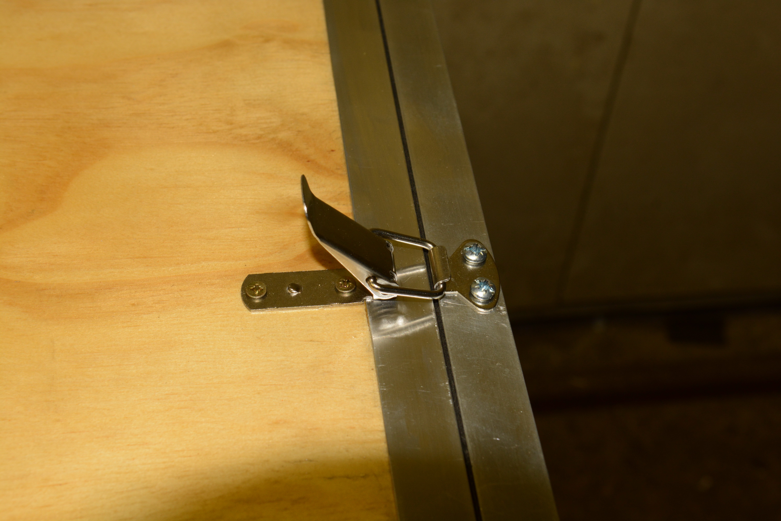
Photo 69 - Close-up of a fitted door latch.

Photo 70 - All door latches fitted and secured in the locked position.
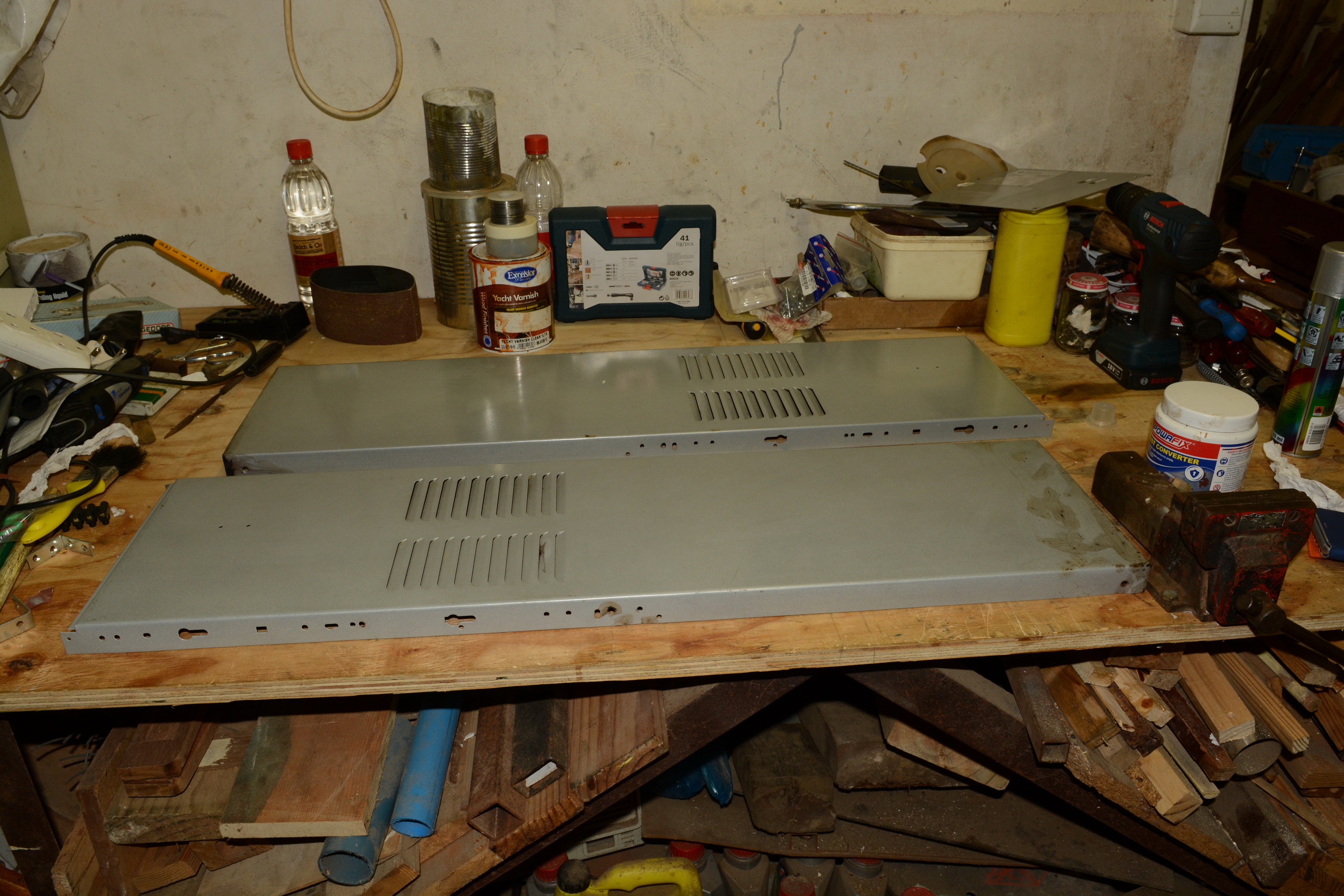
Photo 71 - De-rusted side panels with rust converter applied.

Photo 72 - Right-hand side panel test-fitted in position.
After spray-painting tomorrow, the side panels will be fitted in place and outer mounting brackets for the sides fabricated. The carry handles, necessary for moving around the house with various staircases, will be mounted, one pair on the side panels and one pair on the fermenter chamber walls.
Then all that is left is to finish the wiring harness, make a cover to fit between the side panels and doing a final sanding and varnish coat on the sides of the fermenter chamber. I think there is less than a day's work to go.

Photo 68 - Door latches mounted on top of the chamber.

Photo 69 - Close-up of a fitted door latch.

Photo 70 - All door latches fitted and secured in the locked position.

Photo 71 - De-rusted side panels with rust converter applied.

Photo 72 - Right-hand side panel test-fitted in position.
After spray-painting tomorrow, the side panels will be fitted in place and outer mounting brackets for the sides fabricated. The carry handles, necessary for moving around the house with various staircases, will be mounted, one pair on the side panels and one pair on the fermenter chamber walls.
Then all that is left is to finish the wiring harness, make a cover to fit between the side panels and doing a final sanding and varnish coat on the sides of the fermenter chamber. I think there is less than a day's work to go.

$176.97
1pc Commercial Keg Manifold 2" Tri Clamp,Ball Lock Tapping Head,Pressure Gauge/Adjustable PRV for Kegging,Fermentation Control
hanhanbaihuoxiaoshoudian

$33.99 ($17.00 / Count)
$41.99 ($21.00 / Count)
2 Pack 1 Gallon Large Fermentation Jars with 3 Airlocks and 2 SCREW Lids(100% Airtight Heavy Duty Lid w Silicone) - Wide Mouth Glass Jars w Scale Mark - Pickle Jars for Sauerkraut, Sourdough Starter
Qianfenie Direct

$53.24
1pc Hose Barb/MFL 1.5" Tri Clamp to Ball Lock Post Liquid Gas Homebrew Kegging Fermentation Parts Brewer Hardware SUS304(Liquid Hose Barb)
Guangshui Weilu You Trading Co., Ltd

$22.00 ($623.23 / Ounce)
AMZLMPKNTW Ball Lock Sample Faucet 30cm Reinforced Silicone Hose Secondary Fermentation Homebrew Kegging joyful
无为中南商贸有限公司

$58.16
HUIZHUGS Brewing Equipment Keg Ball Lock Faucet 30cm Reinforced Silicone Hose Secondary Fermentation Homebrew Kegging Brewing Equipment
xiangshuizhenzhanglingfengshop

$7.79 ($7.79 / Count)
Craft A Brew - LalBrew Voss™ - Kveik Ale Yeast - For Craft Lagers - Ingredients for Home Brewing - Beer Making Supplies - (1 Pack)
Craft a Brew

$53.24
1pc Hose Barb/MFL 1.5" Tri Clamp to Ball Lock Post Liquid Gas Homebrew Kegging Fermentation Parts Brewer Hardware SUS304(Liquid MFL)
yunchengshiyanhuqucuichendianzishangwuyouxiangongsi

$28.98
Five Star - 6022b_ - Star San - 32 Ounce - High Foaming Sanitizer
Great Fermentations of Indiana

$10.99 ($31.16 / Ounce)
Hornindal Kveik Yeast for Homebrewing - Mead, Cider, Wine, Beer - 10g Packet - Saccharomyces Cerevisiae - Sold by Shadowhive.com
Shadowhive
bruce_the_loon
Well-Known Member
If I could actually get some time to do a day's work on the chamber...
Not so bad actually. Spray-painted the panels as planned, fitted them in place, finished the wiring harness and started working on the rear cover panel. The carrying handles will be mounted once the side panels are fully secured to the frame.
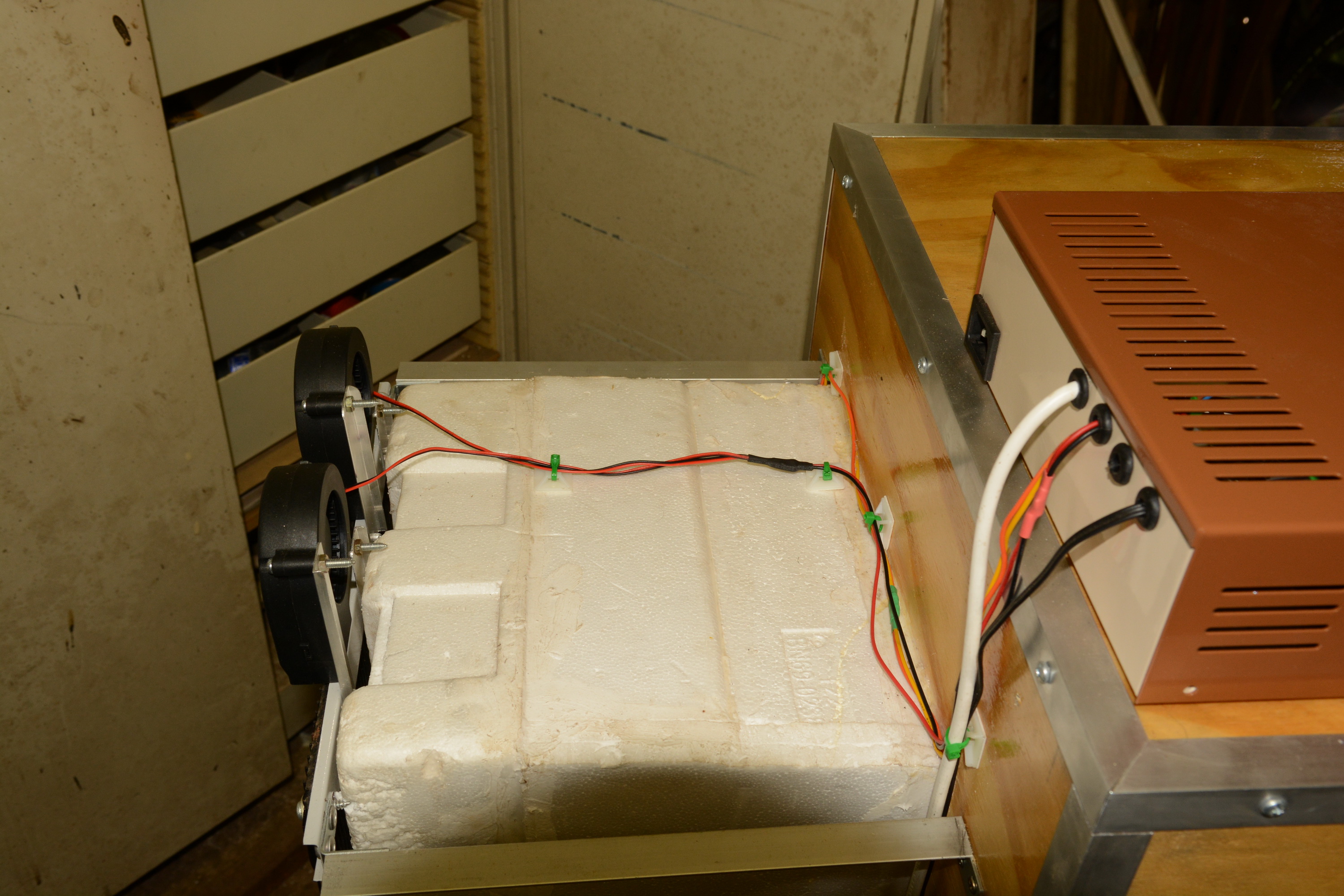
Photo 73 - Completed upper wiring harness with extended blower fan cables and cable-tie blocks.
 .
.
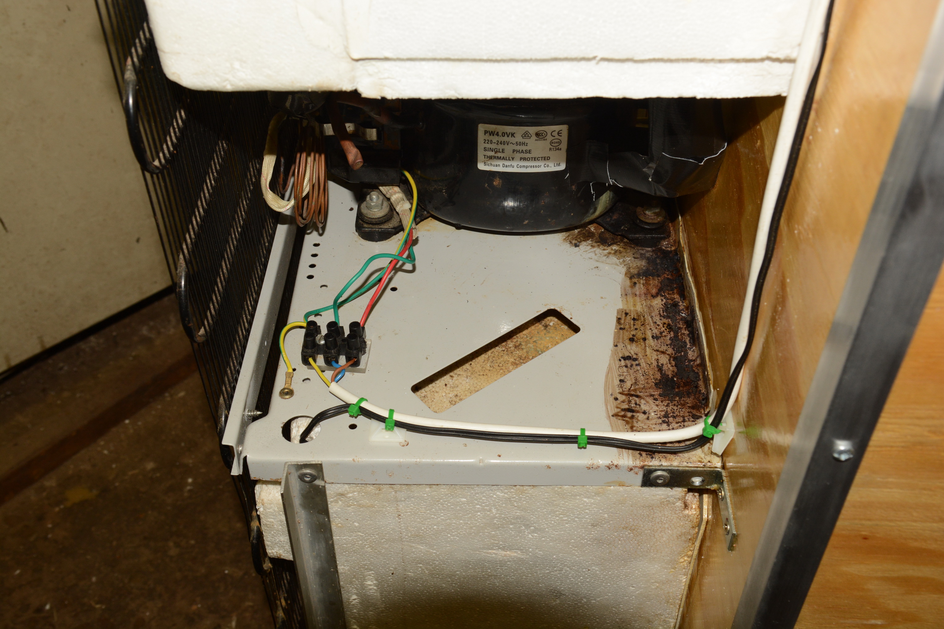
Photo 74 - Lower wiring harness completed with cable-tie blocks.
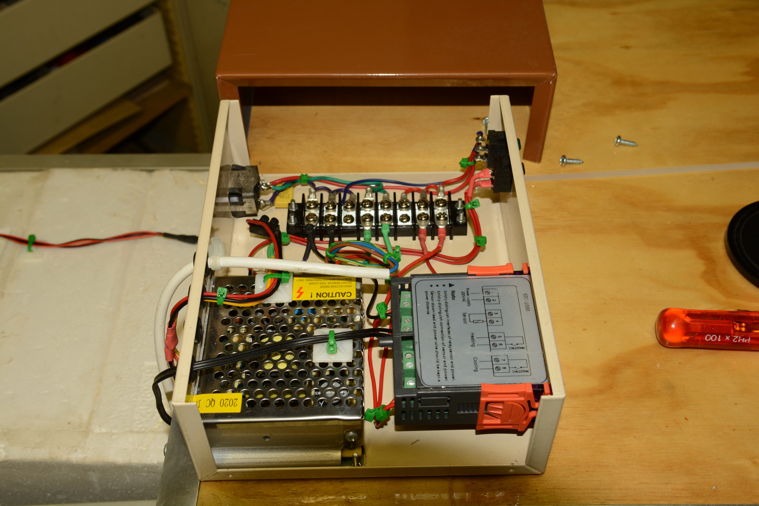
Photo 75 - Completed controller wiring with cable-tie blocks.
That concludes the electrical portion of the project. YAY.

Photo 76 - Spray-painted side panels in all their metallic glory.

Photo 77 - Left-hand side panel mounted in place after being spray-painted.
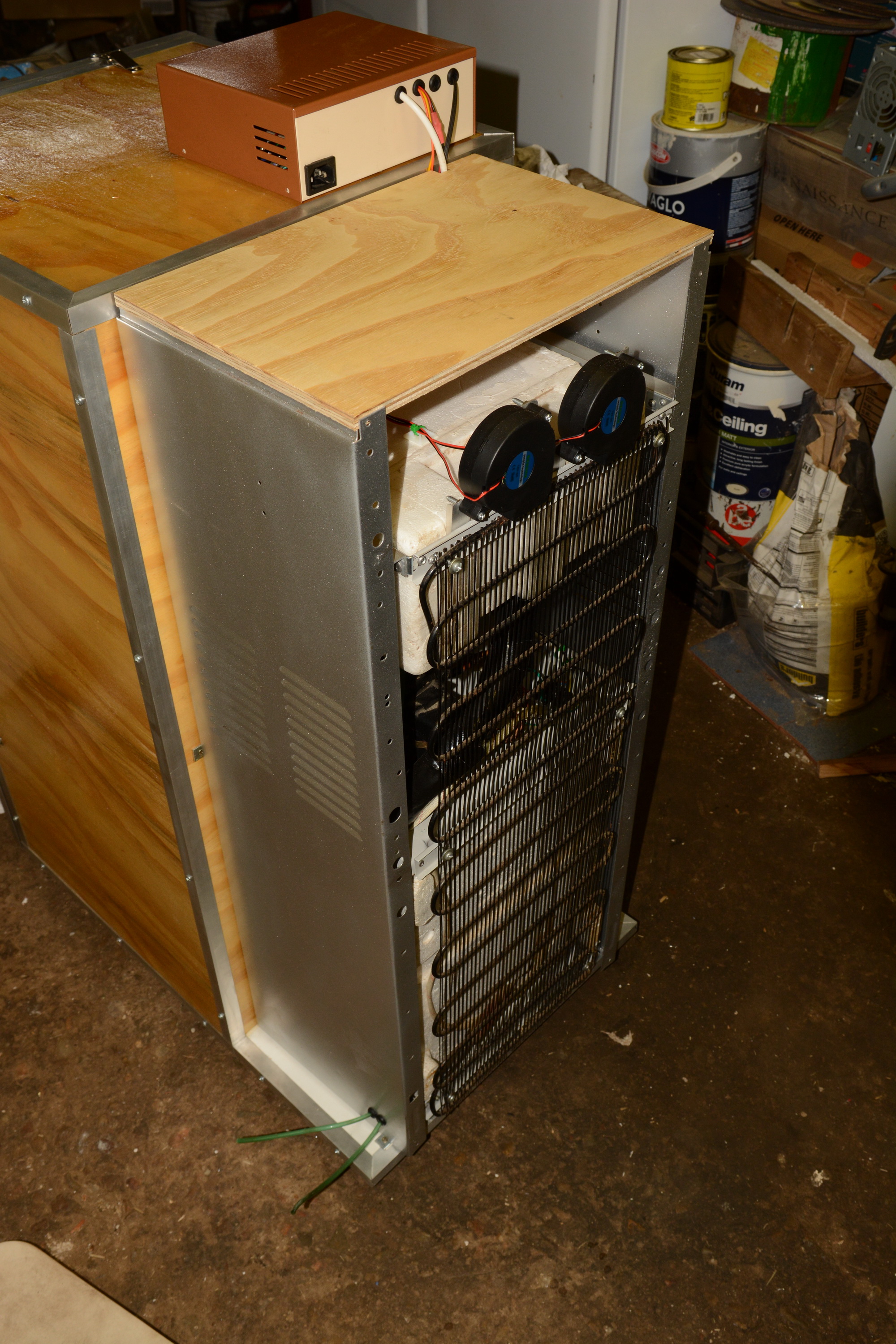
Photo 78 - Right-hand side panel mounted in place after being spray-painted. Note the two drain lines for the condensation emerging from inside.
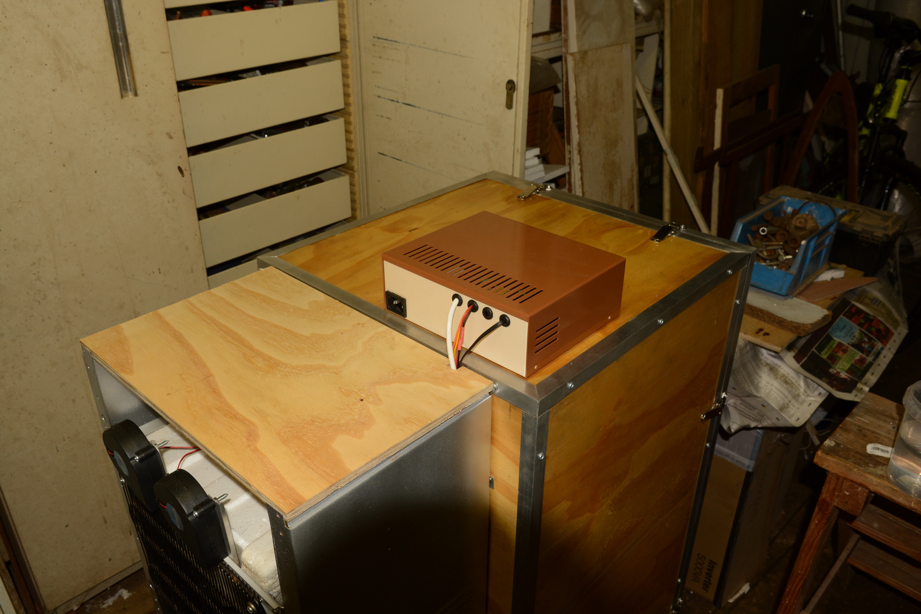
Photo 79 - The plywood cover for the rear section has been cut to size and test-fitted.
Varnishing of the rear cover has commenced with the first coat applied to the visible surface. Debating on whether to edge all four edges with the angle aluminium trim or just the three exposed edges.
The door has been sanded down and received its final varnish coat, It is just the two side plywood panels that need the same treatment and the visual aspects will be completed as well. Mental note, must buy masking tape tomorrow.
This has been quite the journey, developing both my woodworking skills as well as figuring out how the cooling dynamics work in the chamber. I'm pretty sure I've got a fermentation chamber that can not only maintain the set fermentation temperature, but that can cold-crash as well. While the development and construction haven't been as smooth as hoped, the project still came in at about a third of the cost of a suitable refrigerator unit in South Africa.
I'll finish this thread sometime in the next few days with the final update on the handles, rear cover, final bits and pieces and lessons learned. I will be posting a new thread about the completed fermentation chamber and the first brew as soon as it happens.
Not so bad actually. Spray-painted the panels as planned, fitted them in place, finished the wiring harness and started working on the rear cover panel. The carrying handles will be mounted once the side panels are fully secured to the frame.

Photo 73 - Completed upper wiring harness with extended blower fan cables and cable-tie blocks.

Photo 74 - Lower wiring harness completed with cable-tie blocks.

Photo 75 - Completed controller wiring with cable-tie blocks.
That concludes the electrical portion of the project. YAY.

Photo 76 - Spray-painted side panels in all their metallic glory.

Photo 77 - Left-hand side panel mounted in place after being spray-painted.

Photo 78 - Right-hand side panel mounted in place after being spray-painted. Note the two drain lines for the condensation emerging from inside.

Photo 79 - The plywood cover for the rear section has been cut to size and test-fitted.
Varnishing of the rear cover has commenced with the first coat applied to the visible surface. Debating on whether to edge all four edges with the angle aluminium trim or just the three exposed edges.
The door has been sanded down and received its final varnish coat, It is just the two side plywood panels that need the same treatment and the visual aspects will be completed as well. Mental note, must buy masking tape tomorrow.
This has been quite the journey, developing both my woodworking skills as well as figuring out how the cooling dynamics work in the chamber. I'm pretty sure I've got a fermentation chamber that can not only maintain the set fermentation temperature, but that can cold-crash as well. While the development and construction haven't been as smooth as hoped, the project still came in at about a third of the cost of a suitable refrigerator unit in South Africa.
I'll finish this thread sometime in the next few days with the final update on the handles, rear cover, final bits and pieces and lessons learned. I will be posting a new thread about the completed fermentation chamber and the first brew as soon as it happens.
bruce_the_loon
Well-Known Member
So the universe decided to throw some titanium wrenches in the balsa wood gears and I've not been able to get too much done since the last post.
Finished the final varnish coat on all wooden panels with the last coat on the right side going on today. With the other panels completed a couple of days ago, I could also mount the left-hand side carrying handles. The final coat takes about two days to dry, so it will be Saturday before I can mount the right-hand side carrying handles.
Also been brainstorming how to secure the temperature sensor to the fermentation chamber until I can get a thermowell from China to put it in the liquid itself. During the testing phase, I had taped a block of closed-cell insulating foam over the sensor with gorilla tape. It did the job, but the tape is a pain-in-the-butt to use repeatedly and to peel it off the foam. I've now got some self-adhesive Velcro strips, the hooks will be stuck onto the foam block and the loops on the fermentation. Hopefully it will hold the foam and sensor tightly enough against the wall of the fermenter. Any suggestions would be welcome.
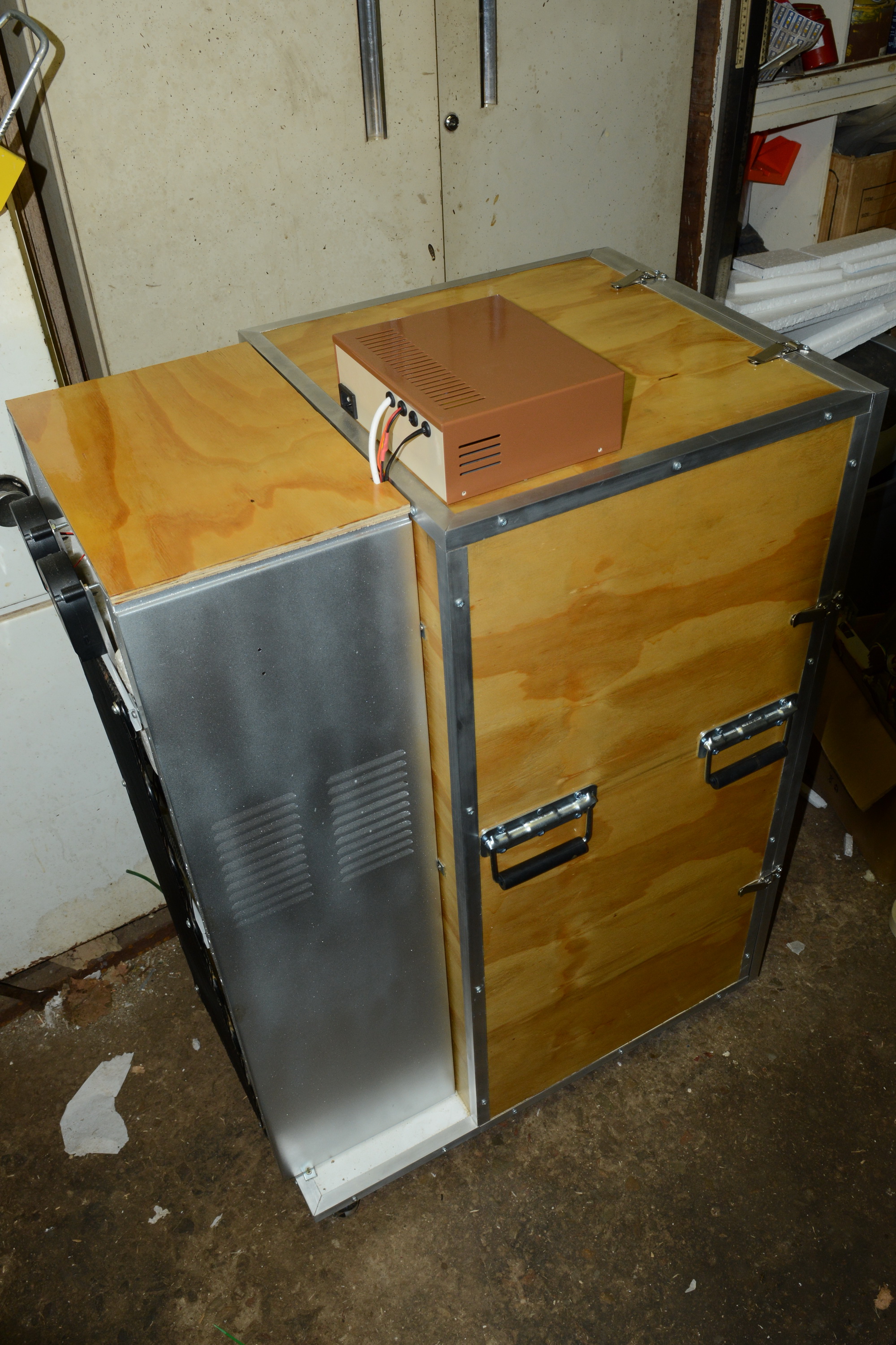
Photo 80 - Left side view of the chamber with the handles mounted.
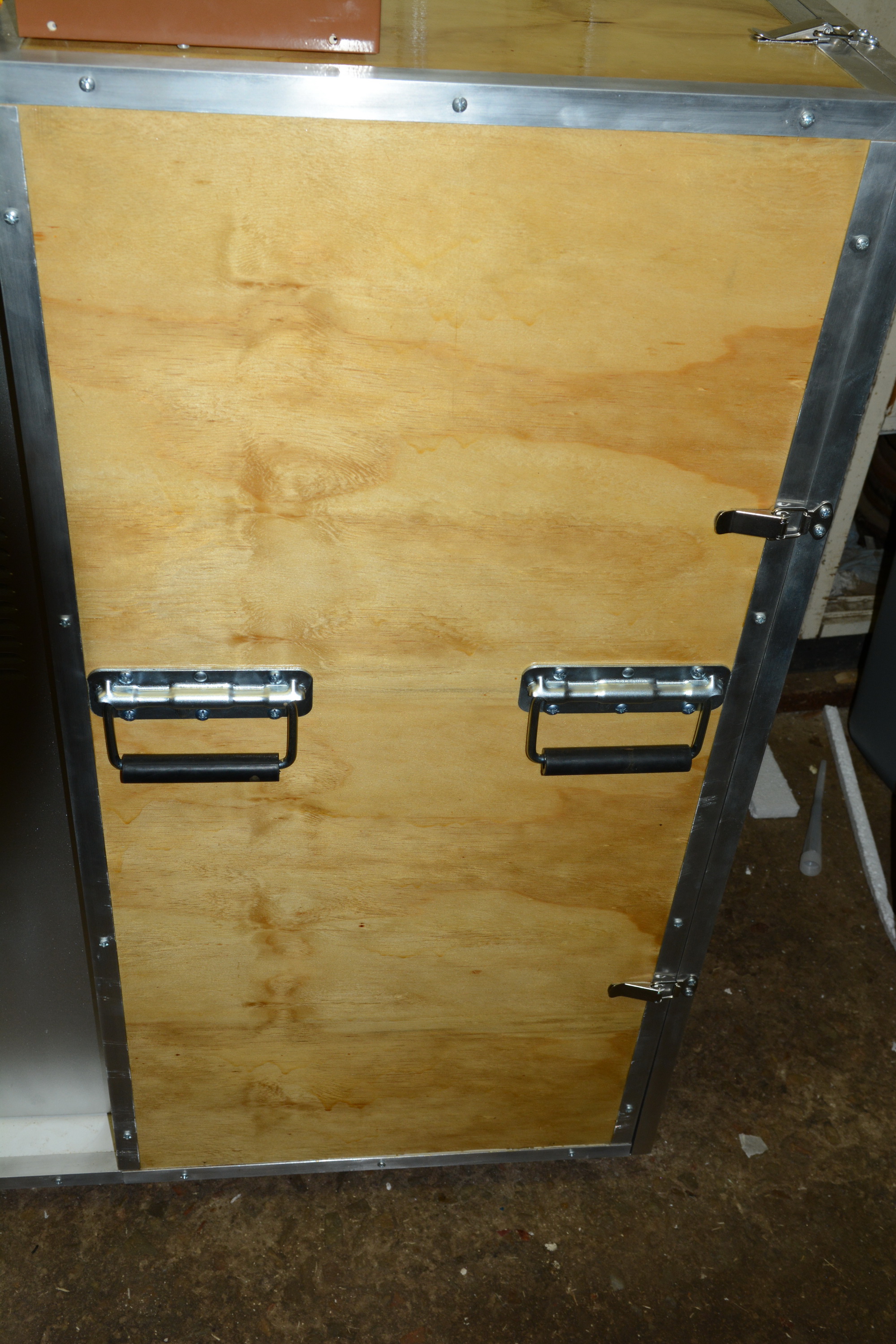
Photo 81 - Closer view of the mounted spring-loaded handles.

Photo 82 - Varnished rear cover missing the aluminium edge trim.
Still to do, edge trim on the rear cover, mounting brackets to secure the side panels to the horizontal frames holding the radiator and the right-hand side handles.
Finished the final varnish coat on all wooden panels with the last coat on the right side going on today. With the other panels completed a couple of days ago, I could also mount the left-hand side carrying handles. The final coat takes about two days to dry, so it will be Saturday before I can mount the right-hand side carrying handles.
Also been brainstorming how to secure the temperature sensor to the fermentation chamber until I can get a thermowell from China to put it in the liquid itself. During the testing phase, I had taped a block of closed-cell insulating foam over the sensor with gorilla tape. It did the job, but the tape is a pain-in-the-butt to use repeatedly and to peel it off the foam. I've now got some self-adhesive Velcro strips, the hooks will be stuck onto the foam block and the loops on the fermentation. Hopefully it will hold the foam and sensor tightly enough against the wall of the fermenter. Any suggestions would be welcome.

Photo 80 - Left side view of the chamber with the handles mounted.

Photo 81 - Closer view of the mounted spring-loaded handles.

Photo 82 - Varnished rear cover missing the aluminium edge trim.
Still to do, edge trim on the rear cover, mounting brackets to secure the side panels to the horizontal frames holding the radiator and the right-hand side handles.
bruce_the_loon
Well-Known Member
And it is done. Complete. Finished. Klaar. No more work.
Finished all the final bits and pieces and tightened the last two screws at 23h13 last night. This weekend I'll be brewing my first batch to have proper temperature control.
Total costing on the system including the controller came to around R2400, about $160 at our current exchange rate. The controller, box and internal parts were about R900 ($60) which would have been incurred with a standard fridge as well. Construction tally came to R1500 ($100) and I believe it looks better than a fridge would. A sweep of the local classified is showing good quality fridges in the R2500 to R3500 range ($160 to $233), so I do think I saved some cash doing it this way.
One last sweep of photos.
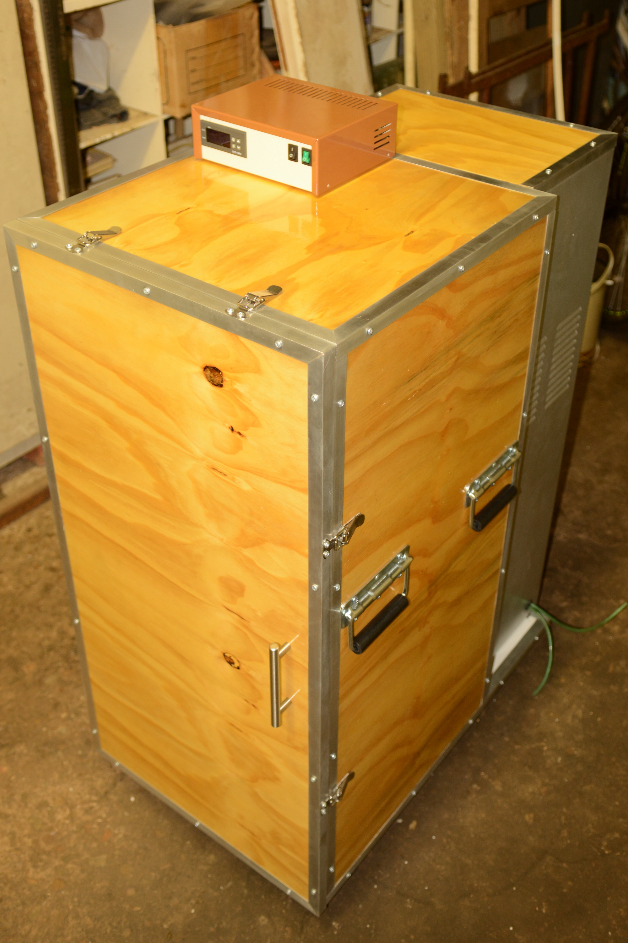
Photo 83 - Front right corner view

Photo 84 - Front left corner view
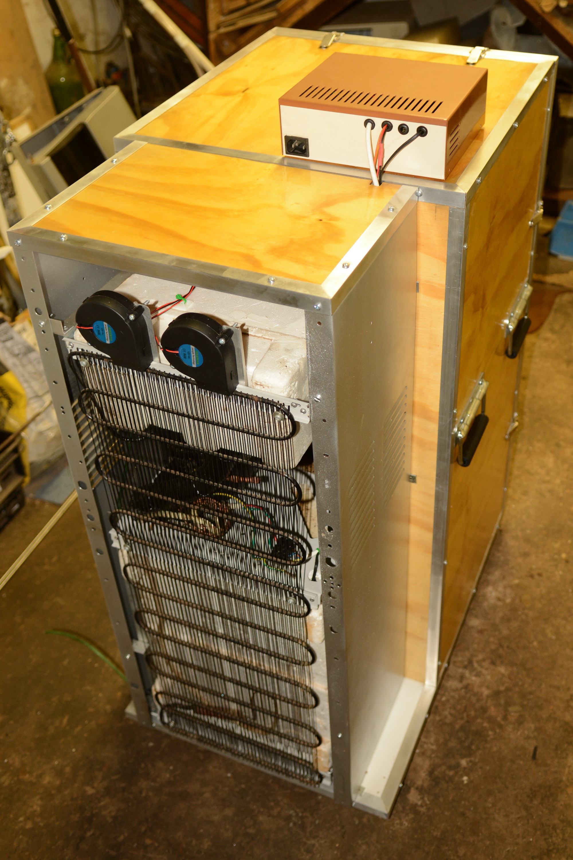
Photo 85 - Back left corner view
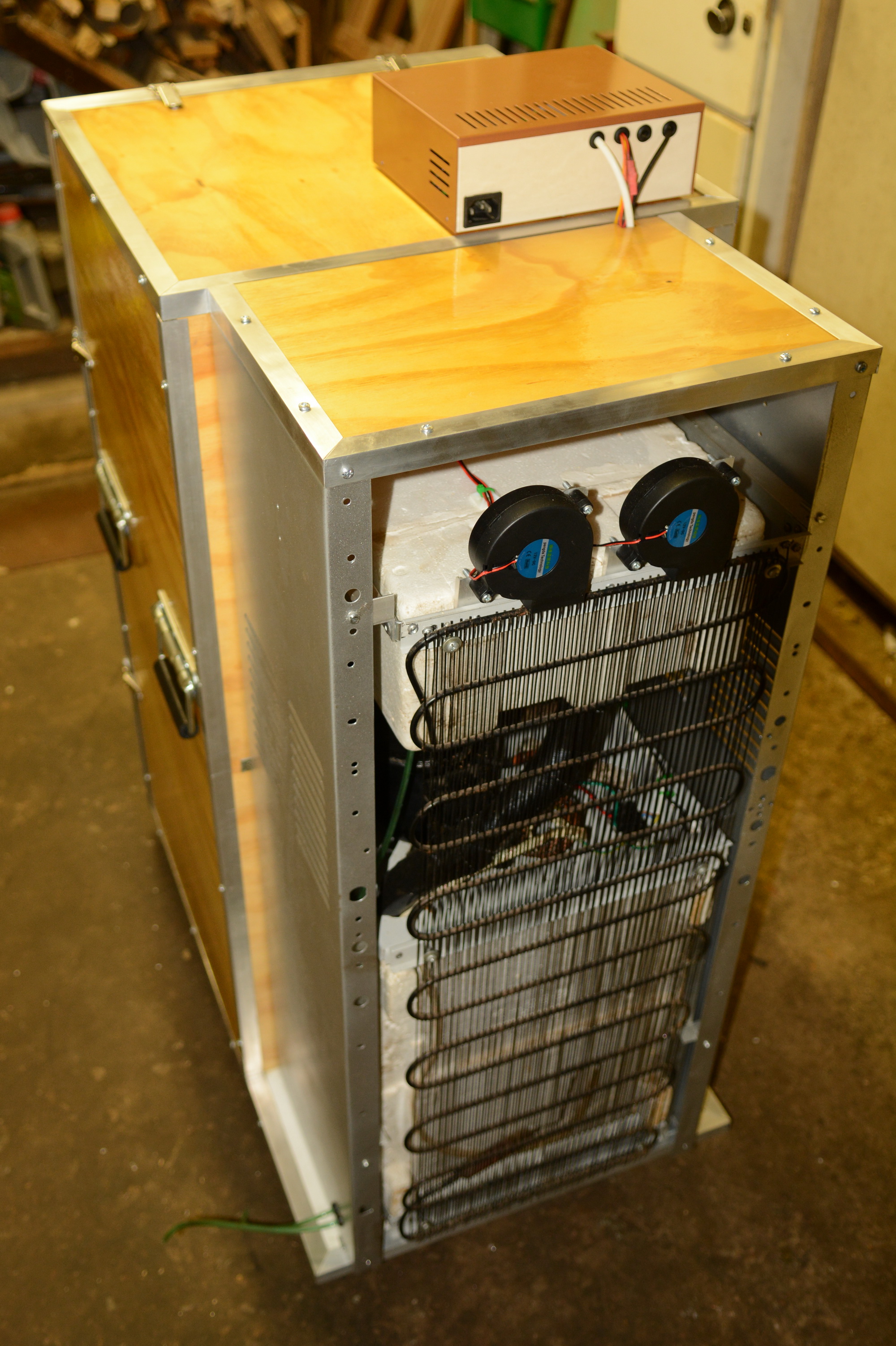
Photo 86 - Back right corner view
Finished all the final bits and pieces and tightened the last two screws at 23h13 last night. This weekend I'll be brewing my first batch to have proper temperature control.
Total costing on the system including the controller came to around R2400, about $160 at our current exchange rate. The controller, box and internal parts were about R900 ($60) which would have been incurred with a standard fridge as well. Construction tally came to R1500 ($100) and I believe it looks better than a fridge would. A sweep of the local classified is showing good quality fridges in the R2500 to R3500 range ($160 to $233), so I do think I saved some cash doing it this way.
One last sweep of photos.

Photo 83 - Front right corner view

Photo 84 - Front left corner view

Photo 85 - Back left corner view

Photo 86 - Back right corner view
madscientist451
Well-Known Member
Nice job, thanks for posting all the photos.
DuncB
Well-Known Member
Bruce you were after a suggestion to secure temp probe.
Somewhere I saw the mention of plumbers putty. I don't have any of this but have used blu tack to hold the probe onto the side of the fermenter and then put a piece of sleeping mat foam on top of this held on with a bungee cord. Much better than my previous double sided tape and foam insulation method.
I like the axial fans you've used to promote airflow over the condenser. I'm not sure which way the hot enters the condenser grid but you might find a cross flow or up flow is better ( heat rising etc ) something to experiment with.
bruce_the_loon
Well-Known Member
Thanks for the suggestion, that might work.Bruce you were after a suggestion to secure temp probe.
Somewhere I saw the mention of plumbers putty. I don't have any of this but have used blu tack to hold the probe onto the side of the fermenter and then put a piece of sleeping mat foam on top of this held on with a bungee cord. Much better than my previous double sided tape and foam insulation method.
I like the axial fans you've used to promote airflow over the condenser. I'm not sure which way the hot enters the condenser grid but you might find a cross flow or up flow is better ( heat rising etc ) something to experiment with.
Regarding the fan position, the hot gas enters at the top of the condenser and exits at the bottom. Most heat is in the upper third and the blowers exhaust over that section. There is a measurable difference of about 15 degrees Celsius on that section with the fans on. The flow seems to dissipate about halfway down.
MuffinJack
Member
- Joined
- Mar 23, 2021
- Messages
- 7
- Reaction score
- 4
Very nice!
Similar threads
- Replies
- 63
- Views
- 4K
- Replies
- 16
- Views
- 743
- Replies
- 21
- Views
- 2K


![Craft A Brew - Safale BE-256 Yeast - Fermentis - Belgian Ale Dry Yeast - For Belgian & Strong Ales - Ingredients for Home Brewing - Beer Making Supplies - [3 Pack]](https://m.media-amazon.com/images/I/51bcKEwQmWL._SL500_.jpg)


