• Please visit and share your knowledge at our sister communities:
  • If you have not, please join our official Homebrewing Facebook Group!

    Homebrewing Facebook Group

BruControl: Brewery control & automation software

Homebrew Talk

Help Support Homebrew Talk:

This site may earn a commission from merchant affiliate links, including eBay, Amazon, and others.
Having some trouble understanding the relationship between the PWM port, its values and the output of the Analog Amplifier 2. Am I correct in believing that the rage of values for a PWM port 0-255?

When I follow the instructions to configure the AA, connecting I1-4 (from P pins on PWM outputs on the UniShield) plus Vcc (5V) and Gnd but no outputs I can get 4.92V output on the AA for all ports while V+ reads 5V when the value of the PWM is set to 255. If I set the PWM output to 0 I get ~0.1V. If I set the PWM output to 127, I get 4.92V but I guess I'm expecting ~2.5V. When I set the PWM value to 50 I get about 3.1V. It seems any PWM value about 100 generates the maximum voltage.

What am I missing?
 
Yep, that's fine and all, but when you say you are still getting ~5v at 127 pwm, that makes me think your pot screws are set wrong. With pwm at 255, turn down the pot until you see some downward movement on your meter. Then try setting 127 and see if you get ~2.5v
 
Hi guys,

I agree with @RiverCityBrewer… sounds like the per-output pot needs adjustment.

Also, usually people power it with voltage above the max… like 12 or 24V. Certainly makes adjustment easier because at 255 the output could be above 5V, giving you the ability to dial it down. With a 5V Vcc, you’ll have to adjust it somewhere else, like RCB says, at 127 to get 2.5V.
 
@BrunDog. Do you have a schematic for Unicon build that you can share?
Also, on your 50amp schematic on your site, you show 22ga wire from the L1 to a 1amp fuse feeding the key switch and estop. Doesn't this need to stay as 6ga upstream of a fuse or breaker?
 
Also, usually people power it with voltage above the max… like 12 or 24V. Certainly makes adjustment easier because at 255 the output could be above 5V, giving you the ability to dial it down. With a 5V Vcc, you’ll have to adjust it somewhere else, like RCB says, at 127 to get 2.5V.

Let me switch it to a 24V feed and retry the alignment for 0-5V tonight. Thanks @RiverCityBrewer and @BrunDog!
 
No, because the load in that instance is a contactor, not a heating element, and the wiring is protected by a 1amp fuse.

He's right. Technically, it would be best to have the fuses fed by a bus that can handle the full current path, but this isn't really practical. Since the fuse inline will blow > 1A (in theory), the wires on either side of it are protected. Hypothetically, the line side wire could get shorted and feel the full brunt of 50A (in that case, it will be repurposed as a miniature space heater, if only for a few seconds).

Email us for the schematic - I can't always translate handle names from here to email. Thanks!
 
Hmmm... sounds like either the channel is blown (seems unlikely if its working, but voltage slope has shifted), or the potentiometer isn't working correctly.

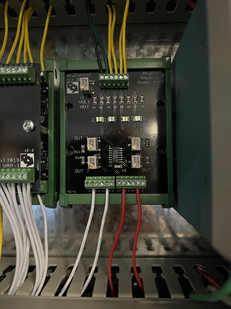
Please give it a visual to make sure all the solder contacts are in tact. Also, if you can take a picture, please do with good resolution so we can see the resistor values.
 
75469A11-4B3D-49AE-B043-529B762C49A2_1_105_c.jpeg
 
Well, maybe don't. I went back to retry things and I mistakenly had the voltmeter on the O3 voltage and adjusted the OUT 4 pot. It adjusted directly with each turn.

It's a minor problem, but I verified this a number of times.

The O3 voltage on my AA2 is actually adjusted with the OUT 4 pot and the O4 voltage is adjusted with the OUT 3 pot. They're backwards!
 
HOLY CRAP! A good bunch of these boards out there and this is the first time I've learned of this... OUT3 and OUT4 potentiometer labels are swapped. Therefore in order to change the range for the third channel, you need to adjust the OUT4 potentiometer, and vice versa. WOW I can't believe we overlooked this and haven't seen it pop up yet (perhaps all these channels are not used by many or everyone adjusts the range to 5V across the board and that's it...)

Thanks for pointing this out @DonWMason... are you ok with it as is?

For others with the AA-2 board, please note this error - while it is minor, please contact us if you would like to discuss options to remedy it.
 
It's strange. The pots are numbered just like you would expect them to be laid out on the board:

OUT 1 OUT 3
OUT 2 OUT 4

But what I'm seeing is this:

OUT 1 OUT 4
OUT 2 OUT 3

I'm totally fine with this. I was chatting with a friend yesterday who was saying it would drive me crazy, but I'm just going to relabel them with a metallic sharpie. No need to send a new one, @BrunDog - it's adjusted and works fine!
 
I just started wiring up my 50amp panel. For the incoming line, how should I terminate the neutral? My Din rail terminals are good up to 10awg and 30amps, but the incoming line is 6awg. The two hot lines go to the contactor and the ground is going to a lug on the backplane, but I am not sure the best way to handle the neutral.
 
I just started wiring up my 50amp panel. For the incoming line, how should I terminate the neutral? My Din rail terminals are good up to 10awg and 30amps, but the incoming line is 6awg. The two hot lines go to the contactor and the ground is going to a lug on the backplane, but I am not sure the best way to handle the neutral.
Your terminal blocks should be sized appropriately to your loads. I use Phoenix UT10 which can handle > 50 amps.

https://www.phoenixcontact.com/online/portal/us?uri=pxc-oc-itemdetail:pid=3044160&library=usen&tab=1
 
True, I'm not running 50+ amps through the neutral, but I'd rather size for worst case scenario, especially since the cost difference is in single dollars.
 
Problem is how do you down-size a 6 AWG wire to a terminal block that will only accommodate 10AWG. My first inclination is dont - get a proper 6 AWG and terminate into that. If the mating terminal blocks don't mix, then I suppose you could split 2x 10AWG off the one block or put two blocks together and split off that.

Lots of ways to rube this, but I don't feel good about recommending those!
 
Ref Post #6,252

@BrunDog
I'm not sure what you mean by "reverse polarity valves". More details needed here.

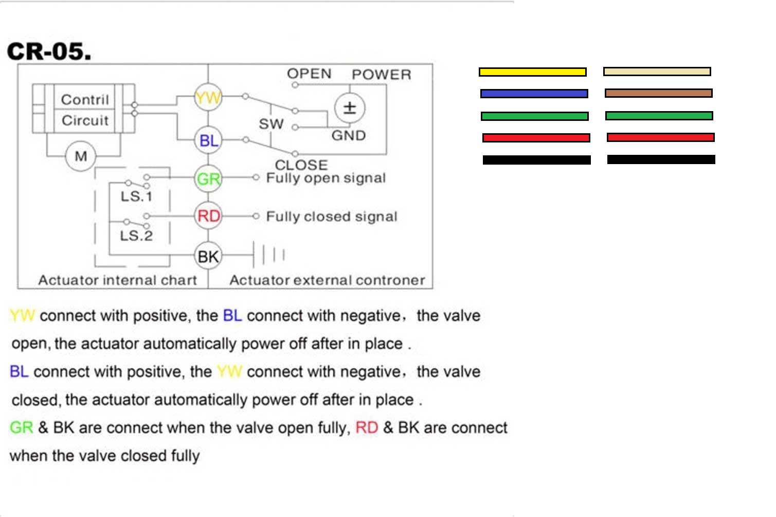
I have 5 wire ball valves that are "reverse polarity valves", They have Yellow , Blue, Red, Green and Black wires

Blue, Red, Green and Black wires are for LED Indicators to tell if Valve is Open or Closed and do not effect operation and are optional to be connected.

You use the Yellow and Blue wires to open and close the valves.

Reverse polarity valves can come in 2 wire as well.

A significant advantage to this type of valve is that it can be left in its last position when power is removed. That way you can leave all the valves "open" when you are between brew sessions with no power.

Power is also removed when the valve is fully opened or closed (except to the indicator circuit in a 5 wire configuration).
If you attach the Yellow to the (+) and the Blue to the (-) the Valve will Open.

Reverse the Polarity

If you attach the Yellow to the (-) and the Blue to the (+) the Valve will Close.


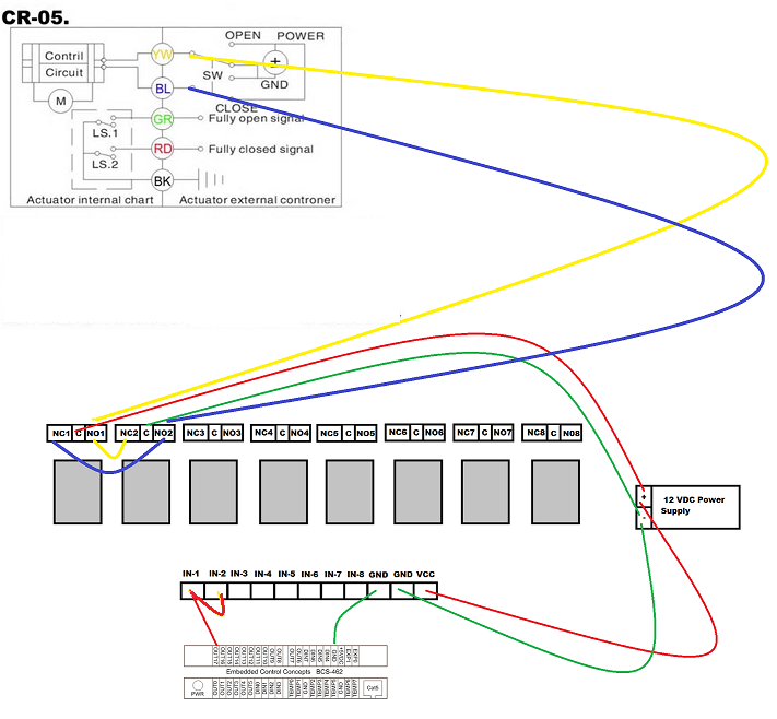
I was planning on using the UM-1 to Control the valves but am having a difficult time trying to figure out how to reverse the polarity. I have plenty of ports for the UM-1 available.

Any help would be appreciated.

I used a Double Pole Relay in the past to do this with the BCS and could do that again (and waste the benefit of the UM-1).

I know about H Bridges and Relays. Just wondering if there was a different solution using just the UM-1?
CR-O5 Wiring.jpg
cr-05 wiring q.png
 
Back
Top