• Please visit and share your knowledge at our sister communities:
  • If you have not, please join our official Homebrewing Facebook Group!

    Homebrewing Facebook Group

BruControl: Brewery control & automation software

Homebrew Talk

Help Support Homebrew Talk:

This site may earn a commission from merchant affiliate links, including eBay, Amazon, and others.
Following up on the 12bit firmware for the ESP32, overall the analog functionality works great. FYI though, I (and a few others) have noticed some issues when connecting a Tilt to boards flashed with the 12 bit firmware, and is immediately resolved by flashing back to the normal firmware. The issues are random disconnects, no readings from the Tilt, and incorrect readings from the Tilt.
 
Upgraded to BruControl Advance this morning... went to set up my Mega 2560 for Ethernet and smoked my ethernet shield when I connected to my PC via USB (ethernet cable was not connected on either end).

D'oh!

So I've ordered a new one but now have to wait to receive it...
 
Has anyone had issues with their BC dropping comms with their controllers? My BC will drop comms with both my ESP32 and ESP8266 for a few seconds then either cycle with trying to reconnect or finally reconnect.

Router shows them connected during those times, and neither controller is resetting during these instances (at least I don't see the devices connected to the ESP32 cycling through as if I switched the ESP32 off then on).

I used Node-RED to see if it maintains a general TCP connection with my ESP32 when BC showed drops, and NR also showed connection drops at the same time, so it's not. BC issue.

Because my router shows the devices as connected and it happens with both controllers, it seems like it could either by the router not sending the comms through reliably or my PC isn't maintaining a steady connection. Figured someone may have seen this before.

[Win 11; ESP32 is running 45O (just updated it to see if it helped here; nope); BC 1.1 build 22]
 
I have a thought, so what kind of router are you running and what kind of WiFi system do you run?

Netgear 4-Stream AX1800 WiFi 6. PC is connected via WiFi 6. I assume the controllers connect via WiFi 4, both 2.4Ghz. This is a more recent development; the PC had always been WiFi 6.

Did that cover the WiFi system question?
 
Netgear 4-Stream AX1800 WiFi 6. PC is connected via WiFi 6. I assume the controllers connect via WiFi 4, both 2.4Ghz. This is a more recent development; the PC had always been WiFi 6.

Did that cover the WiFi system question?
What are your interface settings in brucontrol? You might try increasing the timeout, depending on what it is set to.
 
Netgear 4-Stream AX1800 WiFi 6. PC is connected via WiFi 6. I assume the controllers connect via WiFi 4, both 2.4Ghz. This is a more recent development; the PC had always been WiFi 6.

Did that cover the WiFi system question?
If you look in your controller log, do the drops happen at a certain time/do you see a specific pattern, or are the drops random?
 
Last edited:
If you look in your controller log, do the drops happen at a certain time/do you see a specific pattern, or are the drops random?

Here's a screenshot that shows the connects and drops in a small time frame. My keezer controller stayed connected for a good bit here while my fermentation controller dropped and reconnected a lot, then the keezer joins in the same cycle.

Screenshot_20220306-121029_Word.jpg

Based on Jason's question below, I see the drops do come after 3 seconds consistently, which matches my timeout...

What are your interface settings in brucontrol? You might try increasing the timeout, depending on what it is set to.

My refresh is set to 1 second, and my timeout is set to 3 seconds. I keep the refresh at 1 so my pressure sensor/spunding setup is accurate. I'll change the timeout to 5 and see if that helps.
 
Upgraded to BruControl Advance this morning... went to set up my Mega 2560 for Ethernet and smoked my ethernet shield when I connected to my PC via USB (ethernet cable was not connected on either end).

D'oh!

So I've ordered a new one but now have to wait to receive it...

Whoops... what happened? The shield should not burn up without the Ethernet connected... are you sure it was plugged in correctly?
 
The better log is the interface log, which you need to enable. Also, another way to debug this is to connect a computer to the interface and put it in debug mode... it will report signal strength and when a disconnect occurs.

Also, in my personal (and limited) experience, consumer Wi-Fi tends to be more unreliable than commercial (I think this is where @RiverCityBrewer is going).

I've enabled the interface logs now, so I'll watch those for a bit. So far, I just see the series of Tx and Rx, with an occasional 5 second delay, w/ disconnect then a reconnect.

I'm gonna do a factory reset on my router for good measure. It's being obnoxious when I go into its settings, so something is up with it. It won't load certain settings pages without me having to click on other settings pages then try the ones I want again. Hooray QC processes at major internet tech companies...
 
Whoops... what happened? The shield should not burn up without the Ethernet connected... are you sure it was plugged in correctly?
I have no idea really on what happened… And it was plugged in correctly, as there really is only one way for it to interface with the mega. Someone else suggested that maybe it was a pin that had shorted out.

Nevertheless I have ordered a new one and hopefully it’ll be here in a couple days…
 
I know that there is a limit to the "output" of an interface (Mega, Grand Central, ESP 32 et al.)

What is the practical limit of concurrent outputs? In other words, I have 17 valves, can I control (via UNI or SSR) at the same time? Can I throw in 8 pumps?
What about PID elements x 4? That would be 29 concurrent outputs.

I do not plan on running them all at the same time but maybe a total of 15 concurrent is not out of the question.

I do have a Mega 2560, A Grand Central UNI, and one ESP-32, so the load will be divided, but a practical limit would help in planning the physical wiring if I needed to move one or more Elements to a different interface.
 
Depends on the interface. The MEGA alone has per-pin and group limits. The data sheet is most accurate but not easy to decipher. Practical Information is a bit variable online but I suggest to stay under 20mA per pin and not more than 100mA at one time. That’s at 5V of course. That can indeed be limiting. But this is a $12 board…

The ESP-32 is also limited. I’d keep per pin under 12mA and total to also less than 100mA. That’s at 3.3V.

The UniShield is different as it has purpose intended drivers for the outputs. The limits are listed in the product note, but think 2A per pin, 5 per driver chip, and 12A per bank. That’s at 12 or 24 VDC, so it’s a lot more power. This is designed to drive devices like solenoids, relays, lights, alarms, and small motors directly. You could, for example, drive.a TD-5 off of one. This shield is more expensive of course, but I think the

So bottom line is you need to determine the current loads of all your individual devices and work within the interface limits to make sure it operates properly. Otherwise it might function sporadically or even get damaged if way overloaded.
 
My BK an HLT have triclamp ports slightly above the heater element, presumably for a level switch to protect the heater from running dry. Is this a good place to install the Brucontrol volume sensor and can it reliably function as a safety switch in this configuration? I would hate to cut a hole in the vessel if I don't have to.
 
Depends on the interface. The MEGA alone has per-pin and group limits. The data sheet is most accurate but not easy to decipher. Practical Information is a bit variable online but I suggest to stay under 20mA per pin and not more than 100mA at one time. That’s at 5V of course. That can indeed be limiting. But this is a $12 board…

The ESP-32 is also limited. I’d keep per pin under 12mA and total to also less than 100mA. That’s at 3.3V.

The UniShield is different as it has purpose intended drivers for the outputs. The limits are listed in the product note, but think 2A per pin, 5 per driver chip, and 12A per bank. That’s at 12 or 24 VDC, so it’s a lot more power. This is designed to drive devices like solenoids, relays, lights, alarms, and small motors directly. You could, for example, drive.a TD-5 off of one. This shield is more expensive of course, but I think the

So bottom line is you need to determine the current loads of all your individual devices and work within the interface limits to make sure it operates properly. Otherwise it might function sporadically or even get damaged if way overloaded.
I understand about the bank limits as you have good instructions on the Uni. What I am worried about is the board (Grand Central) itself driving the Uni. Do I need to worry about the board limitations or just your limits per bank on the Uni.
 
For the ports you are using the "D pins" aka Driver output pins... you do not need to worry about the current from the microcontroller board. It is on the micro-amp level. For the "P pins" aka direct Pins, then the normal rules apply as if you didn't have the UniShield (3.3V input limit, <10mA output limit, etc.).
 
I can then use UniShield "P" pins to drive standard SSRs, using the Unishield Bank limitations. Can a UniShield "P" Pin drive a PWM type Out or an Analog Board? I am thinking about another UniShield as I think I will be over the limit without one. I have 5 pumps (March Riptides) and 4 PWM Heating Elements as well as two Selonoid Valves (propane) that All might be "true" or "enabled" at the same time on one Mega 2560. In addition, I have a 12 volt Alarm light that might be "on". There is one addition 12 vdc pump that might be on, but not when at least one of the March Pumps is off (Cooling Glycol for a Plate Heat Exchanger that cools water that is the cooling medium for another Wort plate chiller.

The Unishield I have is dedicated 17 CR05 valves.
 
No need to drive anything via the P pins. Use the driver pins for every output. SSRs still draw 15+ mA so keep the load off the microcontroller. Also keep in mind that the P pins are directly connected to the chip, so as these wires wander around your control enclosure, they are act like antenna that pick up noise and EMI, so the more you can isolate them, the better.

Use all the D pins you want. You have a lot of current available - keep an eye on the limits but I doubt you’ll overload them all.

You can use the P pin to drive analog amp or us a D pin with PWM to drive a DC motor - the driver chips can handle PWM. You can’t drive the analog amp board with the D pins though as they are higher voltage than the amp’s inputs.

Not sure what a March Riptide (do you mean Blichmann?) is, but those are AC and are not variable. Power those with SSRs.

You really should draw a schematic for all of this so you know how you are wiring it and cross-check all the signals, voltages, and currents. “Talking” about wiring is a recipe for burned up devices IMO.
 
For anyone's use. I made a diagram of the Pin/Port associated with the Unishield. I was having trouble wiring without the diagram. You should check it against the Interface Wiring Diagram as I can make mistakes. @BrunDog If this is good, you are free to use in any method you want (such as posting to Brucontrol.com).

UNI Mega 2560 (v45e+) or GrandCentral (v45e+).png
 
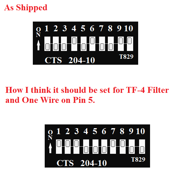
I was looking at my Grand Central Ethernet Unishield and saw that the dip switches were set in a non default way.

I want to maybe attach a TF-3 or TF-4 Filter in the future and thought the switches are no set properly. I also want the capability to add one wire probes off Pin 5.

I have attached a graphic of how it it set now and what I think it should be set to.

One addition question: The Grand Central VCC is a 3.3 v board. Will it run a TF-3 or TF-4?

Oakbarn Grand Central Uni.png
 
Nice!! Can be used in pictogram drawings (easier for some to read than schematics), and can be imported into a drawing program (like draw.io) as well.
I much prefer pics to schematics. I can read schematics but cannot draw them very well. I have tried various programs without much success. Too old a dog for new tricks!
 
Back
Top