• Please visit and share your knowledge at our sister communities:
  • If you have not, please join our official Homebrewing Facebook Group!

    Homebrewing Facebook Group

BruControl: Brewery control & automation software

Homebrew Talk

Help Support Homebrew Talk:

This site may earn a commission from merchant affiliate links, including eBay, Amazon, and others.
Hi there. Not sure what calibration you’re referring to… but for RTDs there is only one calibration - it’s the reference resistor value. Usually it’s 430 or 400 ohms for Pt100 probes.

If you find those temperature results are inaccurate compared to a “gold standard”thermometer reading, you can add additional calibrations such as offset, multiplier, or lookup table. They are processed in order, so if you add an offset, then a multiplier, you’ll get different results than if you add a multiplier then an offset (recommended).

That said,to do it right, one should take readings along the whole range, starting with zero (ice slush bath). Record probe temp vs. gold temp all the way up to boiling. Then either enter data table entries for each, or load those values into a spreadsheetand do a regression. I think the data table is much easier, and it feels like this is an underutilized tool in BC.
Ok, I see the Reference Resistor on the amplifier board. So, if I need to adjust the temperature to match the gold standard temperature, do I change the Linear multiplier value? Or the Reference Resistor value. I noticed on one of your post, I seen you set the Linear Multiplier to 1.0015.
 
Wiring Scematic and other info about using a BruControl volume sensor ?

There are 3 wires
Red: VCC1
Yellow: GND
Blue: Out

Assume (for Mega)
Red: +12 vdc (can take up to 30 vdc)
Yellow:GND
Blue: Analog Pin (A0-A15) and ASSOCIATED Analog Port (100 -115) (0 to +5 vdc )

I did find the Calibration speadsheet and have downloaded it.

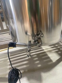
As an aside, has anyone tried an 90 degree Elbow between the sensor and the vessel? Since it measures pressure, I would not think it would make a difference except that you need to calibrate the way it is installed. I would pefer it vertical as it is on the end of a stand and sticks out less with an elbow.
 
Yes you have the wiring correct. However mounting that way is likely not a good idea, as liquid will be left in the Sensor when you are done, unless you take it off and clean it every time. I don’t really love that idea because the diaphragm is sensitive and disassembling to clean could run the risk of damaging it.
 
Could mount so that it drains every time. The elbow is slighty tilted where the elbow will fully drain.
IMG_5585.jpg

This is an HLT so only water although this could be an Electric Brew Kettle if I ever turned to the dark side ;)

It has 2 x 5500 watt Elements and a port where I could add a Steam Slayer (part of manual sight guage)

Laying out the frames for the stand!!!
IMG_5586.jpg
 
Last edited:
My pressure sensors are mounted on an elbow that’s turned up vertically. No issues to far. I make sure to clean and soak often though.
 
if you are going to have it upward, might as well have it fully vertical. The sensor diaphragm won’t actually get wet due to the air gap, but that should be ok. The only real issue I see with this is the sensor is going to get heat radiation from the hot vessel but it might now matter much.
 
I can add bubble wrap insulation to the HLT, I had my Mash Tun wrapped and never has issues with the wrap. I had also insualted with wrap a Chillzilla and it had 185 degree water run through it all the time. Might be good to have it vertical as the sensor wold never get wet! I can also wrap the sensor.
 
Is there a practical limit on concurent pin use on a Mega?
I would suspect that digital out control signals may be a limiting factor. I have search the internet and could Not find limit
 
There are some bank limits IIRC. I can try to find it. If you can keep each pin to less than 15mA you should be ok. On the UniShield, there is no concern because the input current to the drivers is at the micro-amp level.
 
How are others doing their rims return to the mash tun? I just bought a stout MT. It has a triclamp fitting on both outside and inside in the top of the vessel. They sell a triclamp tube with holes in it for recirc and sparge, but I read that it will clog if you recirc the mash through it. Sparging is fine.
 
How are others doing their rims return to the mash tun? I just bought a stout MT. It has a triclamp fitting on both outside and inside in the top of the vessel. They sell a triclamp tube with holes in it for recirc and sparge, but I read that it will clog if you recirc the mash through it. Sparging is fine.
MT drain valve out -> flow meter -> DC recirc pump -> RIM's Tube (vertical) -> MT In (top bulkhead via TC) -> MT inside bulkhead: Loc-Line adjusted just below surface. I don't use any type of filter in the RIM's recirc loop, everything is 1/2" straight through.
 
Any recommendation on flowmeters for rims and sparge? I looked at the plastic adafruit one, but it is out of stock. There are a lot on Amazon, but it is not clear what you are getting and what the materials are. A lot of them seem to be for fuel filling applications.
 
Love these. You can find some cheaper. BUT... check the fittings needed - they are often proprietary adapters for extra $$ and take up length. Also, check the output matches what you need. I wanted to use on my personal rig but the resolution at low flow was too low... cant get an effective measurement at fly sparge rates ~ 1 qpm.
 
Back
Top