BrewPi@ESP8266, no need of RPI and Arduino.

Homebrew Talk - Beer, Wine, Mead, & Cider Brewing Discussion Forum

Help Support Homebrew Talk - Beer, Wine, Mead, & Cider Brewing Discussion Forum:

This site may earn a commission from merchant affiliate links, including eBay, Amazon, and others.
I have yet to change the hostfile on windows to have a host name. I am slightly concerned that the device always connects to ...0.30...even though I've tried many times to set the static ip to ...0.50. That's why I tried to reset the router to see if it is something to do with that IP address.

Is post #532 still the best means of resetting the node mcu? My assumption is that this puts the device into a completely default state.

It’s Windows to be blamed, not the router or BPL if 0.50 is the last numbers of IP.
You have to specify the IP correctly.

I don’t have windows machine. I don’t know how the flasher works, but I bet it works.
 
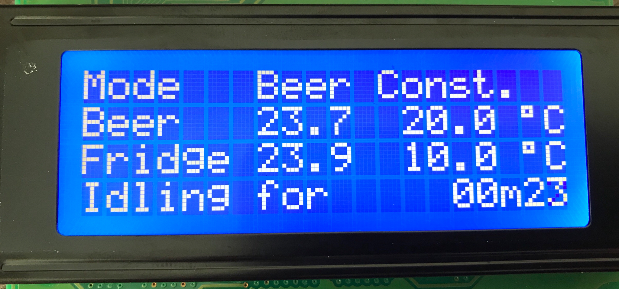
Hey guys, am I missing something here? My brewpiless is accessible from the web, seems to be working ok. I added an lcd screen tonight and the screen is dead, do I need to change some settings to get it to display anything?
 
Hey guys, am I missing something here? My brewpiless is accessible from the web, seems to be working ok. I added an lcd screen tonight and the screen is dead, do I need to change some settings to get it to display anything?

Make sure you have correct LCD type and the wires are connected correctly.

Make sure you have the correct image of options loaded.
 
Hey guys, am I missing something here? My brewpiless is accessible from the web, seems to be working ok. I added an lcd screen tonight and the screen is dead, do I need to change some settings to get it to display anything?
http://vito.tw/wp-content/uploads/2016/08/BrewPiLess-1.png

This image may help you to ensure you have the wiring set up right. Even without brewpiless flashed, my screen was on, blank and bright with zero characters/text on the screen. Once I flashed the BPL bin, I then saw "Initialize Wifi" until that timed out.

@pocketmon, I finally fixed my index page. I deleted all files from the file manager and then reflashed the 2.5.1 bin.
In your change log, you said that you merged Tom's front end. How come it still shows as the default view? A few posts back you said I would have to manually modify his config page to show the LCD timeout. However, I just figured you adopted his design based on the way that was worded.
Also, thank you for posting the OLED video! I was contemplating it as the 20x4 blue screen is too bright. I am definitely going to make the switch.

For those who use the OLED screen, it seems that 3d printed cases are more common with the esp8266/OLED combo than the 20x4 lcd
 
Bad wording. I know. The alternative frontend is created and maintained by Tom. I changed the interface, but I am not familiar with github. Therefore, I merged the change into my github repository. The files in Tom’s repository don’t work with latest version. You have to use those in “hrmljs/dst” folder.

I really like the little OLED LCD. It is cheap and small, yet has space for fifth line. It seems to have better EMI resistance.
 
Make sure you have correct LCD type and the wires are connected correctly.

Make sure you have the correct image of options loaded.

I blindly followed the order of the wiring per the pic provided above without actually checking the pin labels, so I had it configured incorrectly. Now that it is corrected, I am getting a red light on the back but the screen isn't coming on still I have probably bricked it. Its a 20x4 LCD. Also I loaded the stock firmware (2.5.1), just to be sure, also nothing. I have a couple of spare screens, so I will probably just solder another one up and try it.

Edit: I looked at one of the other LCD's and I noted there was a jumper missing from the breakout board at the back. After I put that back on my original one, it now lights up, but no text is showing.
 
Last edited:
I blindly followed the order of the wiring per the pic provided above without actually checking the pin labels, so I had it configured incorrectly. Now that it is corrected, I am getting a red light on the back but the screen isn't coming on still I have probably bricked it. Its a 20x4 LCD. Also I loaded the stock firmware (2.5.1), just to be sure, also nothing. I have a couple of spare screens, so I will probably just solder another one up and try it.

Edit: I looked at one of the other LCD's and I noted there was a jumper missing from the breakout board at the back. After I put that back on my original one, it now lights up, but no text is showing.
I had to keep turning the pot on the back to get the text image
 
OK, so I am making progress, I have the screen on and working, but the text is super dull, is there something I need to do to brighten it up? I have turned the pot as far clockwise as I think it can go (don't want to damage it), and it certainly helps, but you can basically only read the text from an angle.
 
OK, so I am making progress, I have the screen on and working, but the text is super dull, is there something I need to do to brighten it up? I have turned the pot as far clockwise as I think it can go (don't want to damage it), and it certainly helps, but you can basically only read the text from an angle.

Do you supply 5v or 3.3v to the LCD?
I had the same problem and solve it by supplying 5v to the LCD. I was worried about the 5V signal on I2C bus, but it seems to be no issue.
 
The 20x4 white-on-blue LCD requires 5V for the logic and LCD power inputs and ~4V for the backlight.
Like most CMOS signaling devices the logic input pins will work with either a 5V or 3.3V host...

Cheers!
 
Do you supply 5v or 3.3v to the LCD?
I had the same problem and solve it by supplying 5v to the LCD. I was worried about the 5V signal on I2C bus, but it seems to be no issue.

Success! Thanks so much for the help.

IMG_2340.JPG
 
My next question. I read the whole thread but I don't remember seeing anything about changing what's displayed on the LCD. Can you show the current SG rather than the idling time?
 
My next question. I read the whole thread but I don't remember seeing anything about changing what's displayed on the LCD. Can you show the current SG rather than the idling time?

You can't find because it doesn't exist. There is no such setting or function.
 
Well the you go! No worries, it's largely going to be headless anyway, would have been a nice to have.
I haven't gone down the iSpindel route...but that sounds like an awesome idea. The idling time overall doesn't seem too important to me.

Would it be worth while adding an "issue" to github? Maybe this functionality could be implemented in the future?
 
I decided the 20x4 lcd was too bright for me. I ordered a 128x64 OLED to replace it.

I know bigdaddyale is ordering some PCB boards. With that said, could we have some pictures of people's hardware setup? This is because I have a few questions:
1. With pocketmon's ongoing changes, is a breadboard setup still best?
2. Or has anyone used a testing base? Such as this: https://www.amazon.com/dp/B06XHGYPLY/?tag=skimlinks_replacement-20
3. Or is it safe enough to use a perforated solder board or even better...a pcb?

How about cases? I've seen the 1 acrylic case a few pages back as well as pocketmon's prototypes. There are a decent amount of OLED 3d printed options on thingiverse but not a ton for an esp8266 and oled combo.

I'm looking to make one of these for a friend (with the notion that it is early in our development phase). I'd rather not deal with header cables/breadboards that can come lose. Something more permanent would be great. This would even be useful for my own purposes.

Lastly, I will need to order another 1-2 esp8266 devices. Are we able to use a MINI version or will there not be enough gpio pins?
 
Last edited by a moderator:
I decided the 20x4 lcd was too bright for me. I ordered a 128x64 OLED to replace it.

I know bigdaddyale is ordering some PCB boards. With that said, could we have some pictures of people's hardware setup? This is because I have a few questions:
1. With pocketmon's ongoing changes, is a breadboard setup still best?
2. Or has anyone used a testing base? Such as this: https://www.amazon.com/dp/B06XHGYPLY/?tag=skimlinks_replacement-20
3. Or is it safe enough to use a perforated solder board or even better...a pcb?

How about cases? I've seen the 1 acrylic case a few pages back as well as pocketmon's prototypes. There are a decent amount of OLED 3d printed options on thingiverse but not a ton for an esp8266 and oled combo.

I'm looking to make one of these for a friend (with the notion that it is early in our development phase). I'd rather not deal with header cables/breadboards that can come lose. Something more permanent would be great. This would even be useful for my own purposes.

Lastly, I will need to order another 1-2 esp8266 devices. Are we able to use a MINI version or will there not be enough gpio pins?
There wasn't enough interest for me to put in the order for the boards. I need to sell at least 5 boards.If we can get the minimum order I will go ahead and send in the order.
 
Last edited by a moderator:
There wasn't enough interest for me to put in the order for the boards. I need to sell at least 5 boards.If we can get the minimum order I will go ahead and send in the order.
No worries! Thanks for the update. I'll keep an eye out.
 
Received my OLED. Great that I can simply throw a new bin on the device and everything works without fail.

But man, what was I thinking ordering .96" OLED. I can't see anything on that thing!
@pocketmon, does BPL ONLY support the 128x64 - 0.96" or can I use a larger OLED?

EDIT: I see that 128x64 seems to span to larger sizes. The pixel density just suffers. Although Amazon's selection seems to jump in price above 0.96". Might be stuck with the 20x4 LCD.
 
Last edited:
It must be SSD1306 128x64 whatever size.
The requirement of 128x64 is because I use fixed size font that just fits 20x5 characters.
 
If you are interested in placing the order I can help with filling out the order form over at Dirtypcb.
Thanks for the offer! I just took a look and it seems that I would end up with 10 boards. At most I probably need 3 or 4. I didn't explore shipping options but maybe for that quantity it would be worth printing myself. I'm sure I'll bug you if I decide to go forward.
I've never done anything with pcb before. Would you suggest this route with the ongoing BPL changes? I'd hate to have a bunch of paperweights. It does seem that Thorrak's board has been supported for a while, but I'm not sure if there have been any revisions to keep it up to date with BPL.

It must be SSD1306 128x64 whatever size.
The requirement of 128x64 is because I use fixed size font that just fits 20x5 characters.
Thanks for that. I'm probably going to stick with the 20x4 and just use the screen timeout and buy some buttons. Or I might try a color other than blue so I'm not blinded all the time :).
I'll probably order a 2.4" OLED for another esp project. But they're too pricey to also have for BPL which is less critical.

Thanks to both of you!
 
Thanks for the offer! I just took a look and it seems that I would end up with 10 boards. At most I probably need 3 or 4. I didn't explore shipping options but maybe for that quantity it would be worth printing myself. I'm sure I'll bug you if I decide to go forward.
I've never done anything with pcb before. Would you suggest this route with the ongoing BPL changes? I'd hate to have a bunch of paperweights. It does seem that Thorrak's board has been supported for a while, but I'm not sure if there have been any revisions to keep it up to date with BPL.
Every once in a while you have to eat a few orders.I do it mainly to make the boards available to others that would not have an opportunity to get a PCB. It's a fun hobby to build your own board. you end up with a paid for controller in the end. Once you build a controller you will always have it.newer versions might have better bells and whistles but the older units still should function as well as the day they were created.I still use an STC1000+. If you need 4 boards you won't have a problem getting rid of the others. I will pay for one and I send a freebie to the software developer and one to the designer of the pcb. Shipping to US customers is FirstClass nonbendable letter and not much more to ship internationally. If you need help let me know.
 
Every once in a while you have to eat a few orders.I do it mainly to make the boards available to others that would not have an opportunity to get a PCB. It's a fun hobby to build your own board. you end up with a paid for controller in the end. Once you build a controller you will always have it.newer versions might have better bells and whistles but the older units still should function as well as the day they were created.I still use an STC1000+. If you need 4 boards you won't have a problem getting rid of the others. I will pay for one and I send a freebie to the software developer and one to the designer of the pcb. Shipping to US customers is FirstClass nonbendable letter and not much more to ship internationally. If you need help let me know.

I think that is a really good plan. The developer and designer both deserve some love :).
I just took a quick glance at what is available via Thorrak as well as this latest design. Do you have any inputs as to which would be preferred? Looks like Thorrak hasn't had a hardware update in over a year but the RJ11 connector sounds like an interesting approach. But so does using this one for BPL and Brewpi maniac lol. Other than that, I am not nearly knowledgeable to discern the differences.

Maybe this is something better meant for a PM? Either way, I think it's a better use of $ than some perf board. I'd like to slowly get the ball rolling.

I think it is also time for me to go browse the brewpimaniac threads. I have NO equipment that would work with it yet...but still will be good to see what's going on.
I sent you a "conversation" the other day. I think that's the new PM.I like thorrak's PCB and run a version of Fermentrack on it. Thorrak is very active updating Fermentrack. BPL needs to run a special.bin because the pin outs are different.I use the SMD version of his board.I just got done with a run. I was interested to see the other board
 
I sent you a "conversation" the other day. I think that's the new PM.I like thorrak's PCB and run a version of Fermentrack on it. Thorrak is very active updating Fermentrack. BPL needs to run a special.bin because the pin outs are different.I use the SMD version of his board.I just got done with a run. I was interested to see the other board

I think Fermentrack already has the version of @pocketmon's bin linked which uses the same pinout as I used. If it doesn't, someone ping me & I'll get it added.
 
Hi guys, I made brewpiless on thorrak board (level shifter and screws). Everything seem to be working ( I am online, sensors show values, relays working too etc.) but lcd is not working. Only backlight is on (so power is there and it is exactly 5v) but doesnt show values. "Online display" shows right values. I tried another display (same type) but is the same. I used thorrak bin and lcd display 20x4. Any ideas what can be wrong? Thanks.
 
Capture6.JPG
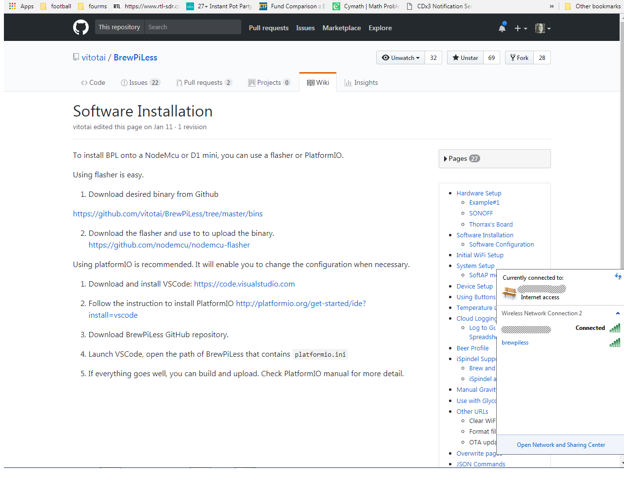
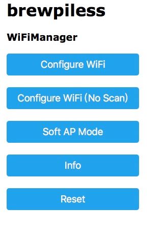
Help with wifi manager. This seems to be the hardest point of the installation for me.I can see brewpiless in the list of connections but when I click on to connect I'm stuck. Wifi manager never pops ups. Is the wifi manager included in BPL2.5 bin?I used NODEMCU to flash BPL2.5 to a D1mini Esp8266
 
Last edited:
WiFiManager acts like a captive portal. I haven't tried setting it up from a computer (only a phone), but you may need to open a browser after connecting to the brewpiless network and try browsing somewhere. That should send you too the configuration page. Otherwise try using a phone to do it and see what happens.

Robert
 
View attachment 560302 Help with wifi manager. This seems to be the hardest point of the installation for me.I can see brewpiless in the list of connections but when I click on to connect I'm stuck. Wifi manager never pops ups. Is the wifi manager included in BPL2.5 bin?I used NODEMCU to flash BPL2.5 to a D1mini Esp8266
I just tedted thetversion 2.52o BPL in a Wemos D1 using the NodeMcu flasher and it worked.

Once connected to the BPL SSID, I just typed 195.168.4.1 at the browser bar and it shows the menu you mentioned.

If it's not working I would try to reset the Wemos (I wrote a step-by-step some pages back).
 
I just tedted thetversion 2.52o BPL in a Wemos D1 using the NodeMcu flasher and it worked.

Once connected to the BPL SSID, I just typed 195.168.4.1 at the browser bar and it shows the menu you mentioned.

If it's not working I would try to reset the Wemos (I wrote a step-by-step some pages back).
When I do what you just did I end up with this screen.BrewPiLess.v2.5.1. Is there a new release of 2.5.2?
This site can’t be reached
192.168.4.2 refused to connect.

Try:

ERR_CONNECTION_REFUSED
 
Bingo.- almost. I was able to get BPL to load but I can't get BPL Thorrak to load 100%I get the infinite spinning loading indicator in the BPL tab of chrome browser. Looks like all systems go with regular BPL.
Steps I had to take
1.Scrub ESP8266 with the procedure in post 534
2. Flash ESP8266, post 532
3. Wait a few min. for SSDI Brewpiless to show up on "available networks"
4. log on to the router and find ISP address
5. Connect to Brewpiless
6.Go to ISP address from step 4, Brewpiless screen should pop up
7. I had to log out and then log back on before Wifi Management screen popped
 
6.Go to ISP address from step 4, Brewpiless screen should pop up
so on step 6, once you connected to the ESP8266 Wifi interface and put in the info for your wifi the ESP8266 will reboot and connect to it, then you can access BPL on a web browser either on "brewpiless.local/" or by its actual IP address, you can find out which ip it is by using "ping brewpiless.local" on a command prompt box.
 
I wonder you connect to 192.168.4.2 instead of the default 192.168.4.1.
 
Back
Top