Counterflow idea

Homebrew Talk - Beer, Wine, Mead, & Cider Brewing Discussion Forum

Help Support Homebrew Talk - Beer, Wine, Mead, & Cider Brewing Discussion Forum:

This site may earn a commission from merchant affiliate links, including eBay, Amazon, and others.

kklowell

Well-Known Member
Joined
Nov 5, 2010
Messages
188
Reaction score
2
Location
Lowell
I'm sure every idea has already been tried, but... would a copper pipe inside a cpvc pipe work as a CFC? I'm envisioning wrapping the copper pipe with copper ground wire, making the outside look threaded, to create some breaking up of the flow. The ends of the CPVC could be sealed around the copper pipe using compression repair fittings cut in half and glued to reducers in the end of the CPVC. I'm thinking that cut in half, or thirds, a 10 foot length length might do it. The ends of the copper pipes would be connected with elbows, and the CPVC sections connected with tees.
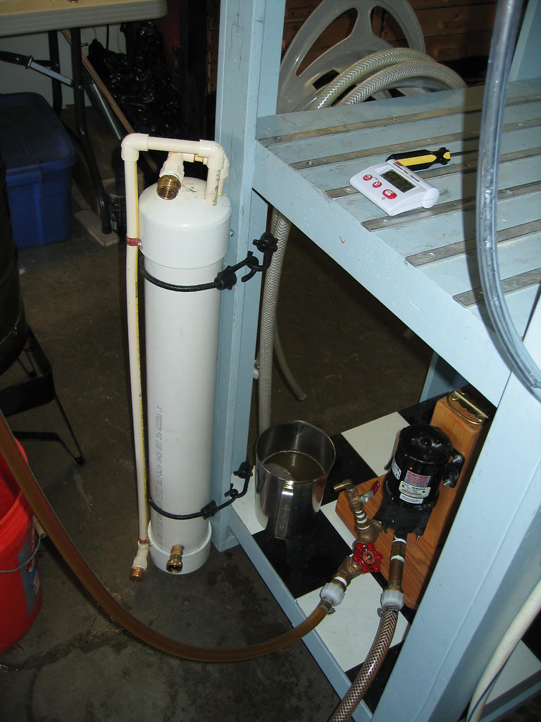
I made a graphic, but I can't post it.
 
It would work, but in order to keep the length down you would have to slow the flow of wort in order to get sufficient heat transfer with only 10' of flow path. The balance between longer fluid flow path vs slower flow velocity might not work in your favor.

I use a 3/8 copper tube inside a 3/4 hose about 25' long and can cool wort from 200+ to 70 with 66 deg. water for 5 gal. in about 10 minutes.

IMO the problem with rigid pipe for the outside will be the possibility of leaks in all of the joints necessary to keep the overall length down. An advantage of tubing through a hose is that things are never straight, causing turbulence in both the flow of water and wort. This removes the need for wrapping the inner pipe with something to create turbulence.
 
Or you could do it like I did using 20 ft of Copper & a PVC jacket:

4684367712_48c8a17a86_z.jpg


4684001647_dc84990572_z.jpg


4684891657_e0c180e571_z.jpg


4684892295_87a171da56_z.jpg


The pics don't show the cooling water inlet or the connectors for the wort as these were shot during assembly before it was finished. You should still be able to get the general idea. When in use it is mounted vertically. This insures that the outer jacket is completely filled with water and eliminates possible air pockets. The cooling rate will meet or beat any.
 
I've been contemplating the same design as the OP but I don't have any allusions that 10 feet will be enough. My rig is about 54" wide so I was going to have 6 passes of 4 feet each. I was going to use 100% copper because I have a few lengths of 3/4" rigid tubing that I found. I had also thought that clear acrylic tubing would be neat with a 1/2" stainless core.

The attraction to this design, for me, is the ability to have the ends connected with silicone tubing. After a few batches, you remove the tubing and run a long handle circular brush through the straight tubes to scrub them out.

It's not very portable though.
 
Cartt22, can you post some more pics of your setup. This looks very interesting.

Or you could do it like I did using 20 ft of Copper & a PVC jacket:

4684367712_48c8a17a86_z.jpg


4684001647_dc84990572_z.jpg


4684891657_e0c180e571_z.jpg


4684892295_87a171da56_z.jpg


The pics don't show the cooling water inlet or the connectors for the wort as these were shot during assembly before it was finished. You should still be able to get the general idea. When in use it is mounted vertically. This insures that the outer jacket is completely filled with water and eliminates possible air pockets. The cooling rate will meet or beat any.
 
Cartt22, can you post some more pics of your setup. This looks very interesting.

Sure thing. Here ya go:

4880832333_0760cec65e_b.jpg


This pic shows it in operating position, but not hooked up to the hoses. The wort enters through the CPVC pipe running down the the left side and exits at the top. The cooling water enters at the brass connection you see at the bottom. This fitting is threaded directly into the wall of the schedule 40 PVC. The cooling water exits at the top in the rear which is out of view, but it is also a pipe fitting threaded directly into the PVC jacket. I actually used a 1/2" NPT tap for these. The hard copper transitions to the cpvc internally. I was concerned that the hard copper pipe might get hot enough to melt the PVC cap where it passes through the jacket end cap during the initial circulation of hot wort, but that concern proved to be unwarranted. This was supposed to only be a prototype, but it works so well I've seen no need to make any changes. If I were to do it again, I would run two additional tubes down the center of the jacket. There's room enough to do so. I would also simply use copper pipe throughout and eliminate the cpvc. I would also probably shorten the overall length to 24" just to make it a little more compact. It's about 30" tall as shown. The 2 ft size using 10 tubes instead of only eight would still provide more than 20 ft total length. It would be a little more than 20 ft if you included the end returns and fittings, but not a whole lot more. OTOH, I've thought about increasing the length to 48" using 10 pipe runs for a total length of 40 ft+, but I think that might be overkill. The primary design goal was to achieve a very high flow rate for both the wort and the cooling water. It took me awhile to figure out how to cram all that pipe into the 4" PVC jacket. The key was to use street elbows at the end returns. This eliminated the need for a short nipple to connect the elbows. I think the cost to build it was about $50 and most of that was in the copper fittings and the PVC end caps. The end caps were about $7.50 each IIRC. The copper pipe wasn't too bad, but the street elbows were rather pricey considering that they are not all that much different than a regular 90 deg sweat elbow.

I can take more pics if you'd like to see more detail, but it may be a couple of days before I can do so. I'm brewing up a 12 gallon batch of Irish Red Ale on Sunday and I could snap some pics of it in action then. Let me know if you want to see anything in particular in more detail.

Here's a bonus pic of my brewing buddy at rest:

3818849951_fabc1b3289.jpg
 
I'm curious how you empty your CFC completely. It would seem that the tubes being vertical would hold a lot of wort.
 
I'm curious how you empty your CFC completely. It would seem that the tubes being vertical would hold a lot of wort.

The volume of the 20+ feet of 1/2" ID chiller piping is less than a quart. I don't bother trying to recover it. I brew 6 or 12 gallon batches which allows for the inevitable losses in the chiller, hoses, etc and when racking. This assures that I will get at least 5 or 10 gallons of finished beer in the kegs or bottles. I find it very annoying to come up short at the end. The excess, if any, gets force carbed in 2 liter PET bottles.
 
Cool... thanks for the quick reply. I like the compact nature of your design, and might just copy it.
 
Cool... thanks for the quick reply. I like the compact nature of your design, and might just copy it.

Thanks, if you do build one, be sure to post back and let us know how it works for you.
 
I though a while about doing such a chiller, then gave up the idea. I have my CFC wrapped around a dead Corney keg that was $5 from Northern Brewer or Midwest IIRC. It makes it pretty compact.

I am not an engineer, but it looks to me like the design as pictured essentially has the wort in wide tubing in a water bath. It looks like you aren't likely to get nearly as much in the way of countercurrent exchange of heat, as happens with a counterflow chiller. The smaller tubing of a CFC gives you more surface area for the volume of wort, also improving efficiency. I ended up going with the CFC, and it has worked out quite well. In fact, I have had to be a little careful not to overchill the wort. Cheap, simple, effective, & hard to beat.

Wanna race?
 
It looks like you aren't likely to get nearly as much in the way of countercurrent exchange of heat, as happens with a counterflow chiller. The smaller tubing of a CFC gives you more surface area for the volume of wort, also improving efficiency.

I built the exact same internal component out of 2X10' type L pipes. (16 X 18") and sunk it in a bucket of ice water. Still ended up stirring the ice water on brew day to achieve my desired results. Next brew I threw a small pump in the ice bath for a light circ, which helped a bit. Its been fun to tinker with only, with not a significant amount of difference than a good CFC. Good timing on this post, lets see what happens.

______
GPB
 
Back
Top