Interesting pump flow discovery/idea

Homebrew Talk - Beer, Wine, Mead, & Cider Brewing Discussion Forum

Help Support Homebrew Talk - Beer, Wine, Mead, & Cider Brewing Discussion Forum:

This site may earn a commission from merchant affiliate links, including eBay, Amazon, and others.

dzimm27

Active Member
Joined
Oct 2, 2011
Messages
31
Reaction score
4
Location
Fort Worth
Working on final flow setup for my eBIAB system and wanted to throw out something interesting. This is of course based on @Bobby_M 's design (and he did the kettle). I'm enamored with running recirculation through my counterflow chiller until I learn my own hard lesson that this is a bad idea. Attached is a pic of the first test run and just to confirm, fittings are all 5/8" and 1/2" tubing. Wort (or test water) exits through a pickup tube and goes to a Riptide pump, then through a Stout counterflow chiller, then up to a tee that splits to the low recirculation port and the high recirculation port (trying this vs through the lid, but have a TC port there as well if it proves necessary). Originally I had a valve placed between the tee and the high recirculation port like in Bobby's design, but I discovered that even wide open, test water would not flow up that hose UNLESS the valve to the low recirc port was partially closed. Once partially closed I start getting flow both to the high and low ports. The restricted flow of the counterflow chiller basically makes where we don't need the second valve leading to the high recirc port, so I removed it.

IMG_3212.jpg


What I'm wrestling with now (of course before having had the opportunity to do an actual brew on the system and finding out myself - admittedly) is whether or not the total flow restriction is going to be detrimental in any way. Reading up on fluid flow through two possible paths (in this case, high/low recirc ports, even with the extra head of the lift to the high port) will be equal to the input flow, but will be distributed between the two paths based on the restriction of the two paths. So whatever flow rate makes it through the counterflow chiller (ignoring tubing length loss) will make it back to the kettle.

What I could do however is apply that same principle to the counterflow chiller by placing a tee in front of the CF input and output and connecting it like the attached drawing, using only one valve (the dark circle with the little handle sticking out). This would allow an effective "bypass" of the counterflow chiller because when that valve is open, it has the full 1/2" tubing available to flow through and remove any flow loss from the CF chiller. The actual flow based on my understanding of fluid flow through two paths mentioned earlier is that there would still be flow through the CF chiller AND the direct hosing, but given the larger ID, the majority of the flow would be through the "bypass" and the end resultant flow as it exits that last tee should be equal to the input, effectively removing any flow restriction while that valve is open. Then, when chilling is needed, the valve could be closed and flow reduces but 100% of the flow is chilled. Additionally this avoids any need for disconnecting hoses during the mash, boil, chill to whirlpool temp, whirlpool, and final chill to the fermenter.

IMG_3246.jpg


It had occurred to me that if I put this bypass in, I'll then need to add that valve back in before the upward hose to the top recirc port as the flow rate will increase.

Has anyone done anything like this and have feedback/suggestions? Anything I may be missing here in my scheming? Primary goal here is to avoid moving hoses (and handling hot fittings during a brew) and having spillage. Also, bonus pic of my new 18" x 24" stainless table that I cut down to put it on. Bottom shelf is a little cramped but will work fine.

IMG_3247.jpg
 
Apologies if I'm misunderstanding anything, but why would you include the CFC in the path at all during a mash? Currently, I use camlocks and only put my CFC in the path in the last 15-20 mins of my boil. I've bought some 3-way valves from @Bobby_M for my next system that I'm currently building to solve that.
 
Apologies if I'm misunderstanding anything, but why would you include the CFC in the path at all during a mash? Currently, I use camlocks and only put my CFC in the path in the last 15-20 mins of my boil. I've bought some 3-way valves from @Bobby_M for my next system that I'm currently building to solve that.
Couple reasons actually:
  • Initially during design of this, I was needing to do a mash schedule that started high, then needed to drop temperature for an enzyme addition/rest before going back to a higher final step temp. I brew gluten free grains and this was the prior mash schedule I would follow. There are newer enzyme regimens that avoid this drop in temperature, but had built this into the design to be able to accomodate this if needed
  • To avoid having to move/handle hot fittings during the mash/boil process and avoid spillage/mess
The bypass method I mention would allow the ability to remove the restriction of the CFC during mash/whirlpool, yet since the CFC will always see some flow while the pump is running, it's always being flushed/sanitized regardless of valve status. This also allows me to use all TC butterfly/linear flow valves vs any ball valves.

That said, thanks for the question/challenge. If what I'm scheming here doesn't make logical sense, that's what I need to hear.
 
To avoid having to move/handle hot fittings during the mash/boil process and avoid spillage/mess
For that part of it, I can highly recommend a slightly oversized pair of the Rubbermaid (or equivalent) rubber gloves with a pair of cheap close fitting cotton work-gloves inside. [ https://www.amazon.com/EvridWear-Po...0756&sprefix=cotton+work+gloves,aps,87&sr=8-5 ] ...I keep a rectangular bucket under my brew-rig connections, and with that glove combo, I can even reach into boiling wort if I need to without any burns.
As to your temperature drop; Isn't using a CFC a bit extreme?..wouldn't you require already hot, temperature controlled water at the CFC inlet to avoid dropping it too low?
 
For that part of it, I can highly recommend a slightly oversized pair of the Rubbermaid (or equivalent) rubber gloves with a pair of cheap close fitting cotton work-gloves inside. [ https://www.amazon.com/EvridWear-Polyester-Protection-Industrial-Construction/dp/B082BJSBRK/ref=sr_1_5?crid=223V0QSSD2VTU&keywords=cotton+work+gloves&qid=1688320756&sprefix=cotton+work+gloves,aps,87&sr=8-5 ] ...I keep a rectangular bucket under my brew-rig connections, and with that glove combo, I can even reach into boiling wort if I need to without any burns.
As to your temperature drop; Isn't using a CFC a bit extreme?..wouldn't you require already hot, temperature controlled water at the CFC inlet to avoid dropping it too low?
Right, gloves would be required for sure, and it's doable for sure. With your 3 way valves I see you are clearly thinking along the same lines of not wanting to have to disconnect if you don't have to.

For the temperature drop, will be honest, have never used a CFC before this and have no idea how quick it will be. In my prior "rollercoaster mash" schedule I had to get it up to 190F for one enzyme, drop to 145F for a second enzyme addition, and then back up to 190F. Sounds crazy to barley brewers I am sure. That large of a drop had me adding ice and guessing previously. That's all moot because I don't need to drop temp anymore with new modern gluten free mash schedules, but that was the original thought/planning. The secondary (which I guess now is the primary) goal was the ability to not have to disconnect hoses during the process.
 
I’m not an engineer but would a 3/8” ID tubing leading to the upper recirc create more pressure and better upward flow? I built a kettle based on the Brewhardware design but I use an immersion chiller so I don’t have these issues. I move my Jaded Hydra IC between the kettle and a tubtrug of sanitizer as needed for temperature control. My prior (2 kettle) rig had 2 Blichmann pumps, plate chiller and more valves/tubing/fittings than a 5 gallon batch beer brewer really needs. It looked impressive, but was overly complex, created more wort loss, much longer cleanup time, all with no noticeable difference in beer quality. I now have a system with 2 ball valves, 1 small but powerful (Topsflo) pump, 1 tee and about 40” of tubing. As a result, I have minimal wort loss, no need to disconnect or reroute any plumbing throughout the entire brewing process and cleanup is a breeze.
 
I think my system does what you're trying to do. I'm at the store filling up some Reverse Osmosis water for the brew I'm about to do. When I get home and start the brew I'll link some pictures.
 
While total overkill, I did something similar for mash, whirpool and whirlpool with chiller. It's nice for the whirpool hops to be able to cool to 170ish, switch the valves to bypass the chiller and get a strong whirlpool, then switch back to chilling. One thing I'm going to try tomorrow is to send some wort to the top of the kettle during chilling at the end of the brew day. Sometimes I've seen where it's cooled the wort at the bottom of the kettle but isn't sufficiently mixing with the wort at the top. It helps to have the whirlpool port point up a bit to encourage some mixing.

1688398623226.png
 
I think the restriction of the CFC would be fine if you can verify that the flow hitting the whirlpool port is actively mixing the kettle.
I honestly need to hook it up without the CFC in line to see the difference in force, but the bottom whirlpool port was pushing water and mixes. Could visibly see it in the water when doing a water test filled to just over the false bottom, but have yet to do one at full boil volume - so speed of whirlpool may be an issue (hence the idea of the bypass). That said, until I do it I won't know. Through the CFC might still be sufficient, albeit slower.
 
While total overkill, I did something similar for mash, whirpool and whirlpool with chiller. It's nice for the whirpool hops to be able to cool to 170ish, switch the valves to bypass the chiller and get a strong whirlpool, then switch back to chilling. One thing I'm going to try tomorrow is to send some wort to the top of the kettle during chilling at the end of the brew day. Sometimes I've seen where it's cooled the wort at the bottom of the kettle but isn't sufficiently mixing with the wort at the top. It helps to have the whirlpool port point up a bit to encourage some mixing.

View attachment 823934
This looks great. I think you could do without the lower valve on the pump "tee" up to the whirlpool port "tee". Definitely a similar-but-different bypass method. Good point on the slight angle up in the whirlpool port. Probably would help with distributing the chilled wort without affecting whirlpool strength too much. I presume the white crimp connector on the hose to the mash recirc port is because partially opening the butterfly does not give you enough control to regulate flow up there?

I bought all butterfly valves to start with but then switched to the Blichmann Linear valves due to size/weight. Still have the butterflys unused (probably will sell). Interesting thing on the Blichmmann's is that their TC (maybe NPT) Linear flow valves have a flaw in them that the one built onto the RipTide does not. The saftey clip on them doesn't stop the linear valve knob/mechanism from fully unscrewing and being removed. Instead all it does is quite annoyingly stop you from being able to close the valve again once you've accidentally opened it too much (unless you remove the safety clip). On the RipTide it stops you at full open from going too far, which is what it really should do on the standalone valves. I contacted them about this after order regarding return/replacement and they confirmed it was a flaw in the design and would have to have that corrected in the next production run and would send replacements vs doing a return. They've since stopped responding to my emails and I'm sure they aren't looking forward to replacing these given it seemed like everything they had shipped wasn't correct. The good news I guess is when you unscrew them too far it takes extra force to pull them out and then (hopefully) is unlikely to come loose under the low pressures we're dealing with.

Edit:
Yeah the lower valve up to the whirlpool is probably unnecessary.

The white hose crimp is there because I haven't removed it. I originally put it there to stop any excess drips when removing the basket, but I pretty much just drain that whole tube now, so it isn't necessary.

The valves have been fine for flow control, in combination with the linear valve on the pump.
 
While total overkill, I did something similar for mash, whirpool and whirlpool with chiller. It's nice for the whirpool hops to be able to cool to 170ish, switch the valves to bypass the chiller and get a strong whirlpool, then switch back to chilling. One thing I'm going to try tomorrow is to send some wort to the top of the kettle during chilling at the end of the brew day. Sometimes I've seen where it's cooled the wort at the bottom of the kettle but isn't sufficiently mixing with the wort at the top. It helps to have the whirlpool port point up a bit to encourage some mixing.

View attachment 823934
Nice table setup, where did you get the mount for the Auber? Looking to do something similar with my Auber. Appreciate the feedback.
 
Remember flow is proportional to the 4th power of the tube radius.
So doubling a tubes radius increases flow 16 times. In general terms.
So keep the narrow tubes out of your system until you really need them.
 
Where do you tap into this setup to transfer to fermenter?
The line going up to the sight glass/top of basket. It gets filled with star san then, pushed into a cup for a second before going into fermenter.
 
I see, so you fully cool it then transfer.
I was assuming you would transfer through the CFC after the wort was partially cooled at the kettle, but could not see an easy line switch.
Yes, I fully cool in kettle, bypass the cooler for a stronger whirlpool, then I let it sit to drop out as much as possible before transferring.
 
Interesting thing on the Blichmmann's is that their TC (maybe NPT) Linear flow valves have a flaw in them that the one built onto the RipTide does not. The saftey clip on them doesn't stop the linear valve knob/mechanism from fully unscrewing and being removed. Instead all it does is quite annoyingly stop you from being able to close the valve again once you've accidentally opened it too much (unless you remove the safety clip).
I’m just about to buy a couple of these for my ebiab, but am not following what you are saying here. I guess without having seen one, not sure of this safety clip. Could you show a pic of what you are talking about? Do you think they could be modified to work? Also, do you know if these work with flow going in either direction? I’m wanting to install the NPT versions with the male NPT connected to the kettle coupling, and the female connected via fittings to the pump.
 
Last edited:
I’m just about to buy a couple of these for my ebiab, but am not following what you are saying here. I guess without having seen one, nit sure of this safety clip. Could you show a pic of what you are talking about? Do you think they could be modified to work? Also, do you lnow if these work with flow going in either direction? I’m wanting to install the NPT versions with the male NPT connected to the kettle coupling, and the female connected via fittings to the pump.
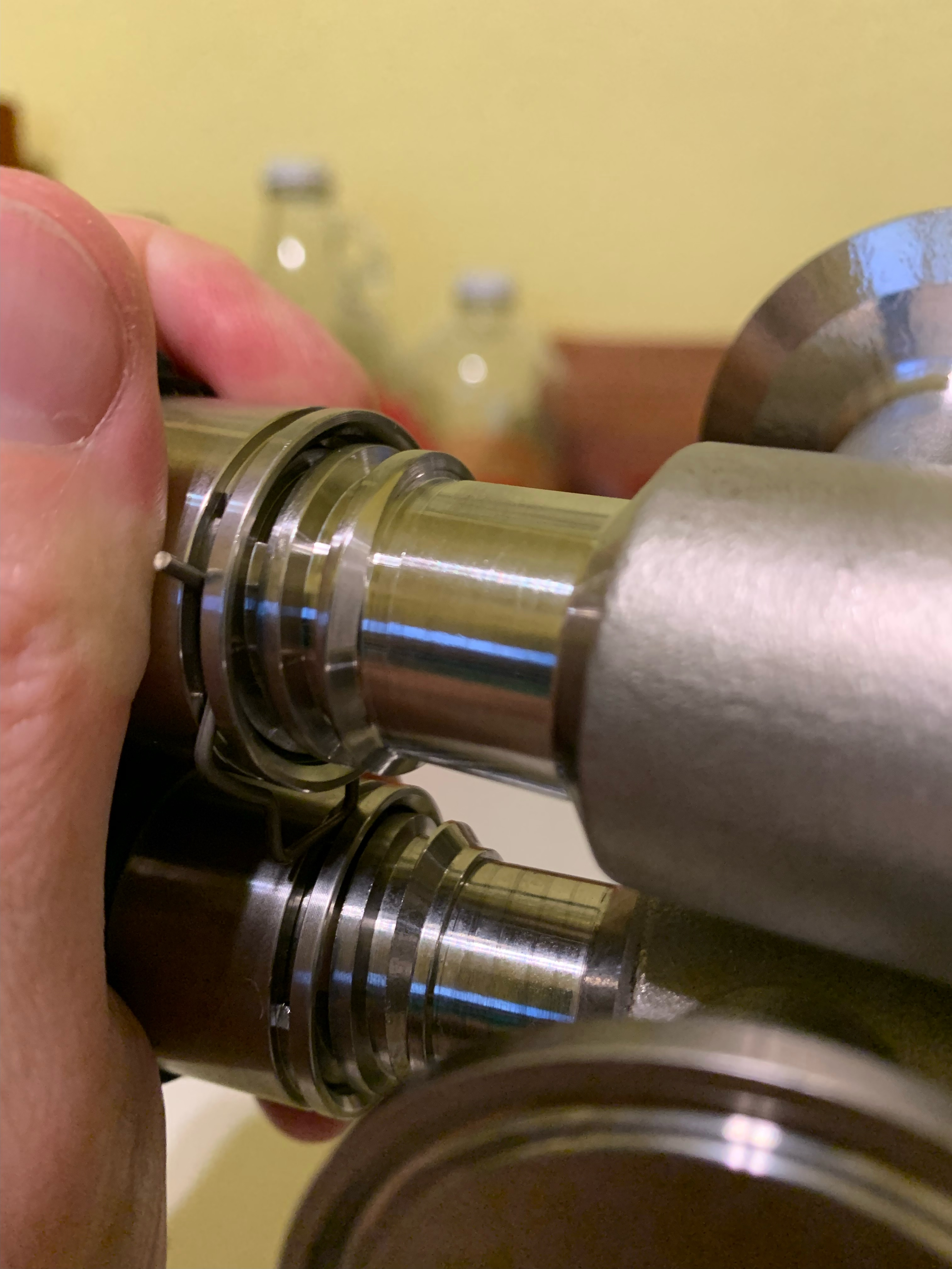
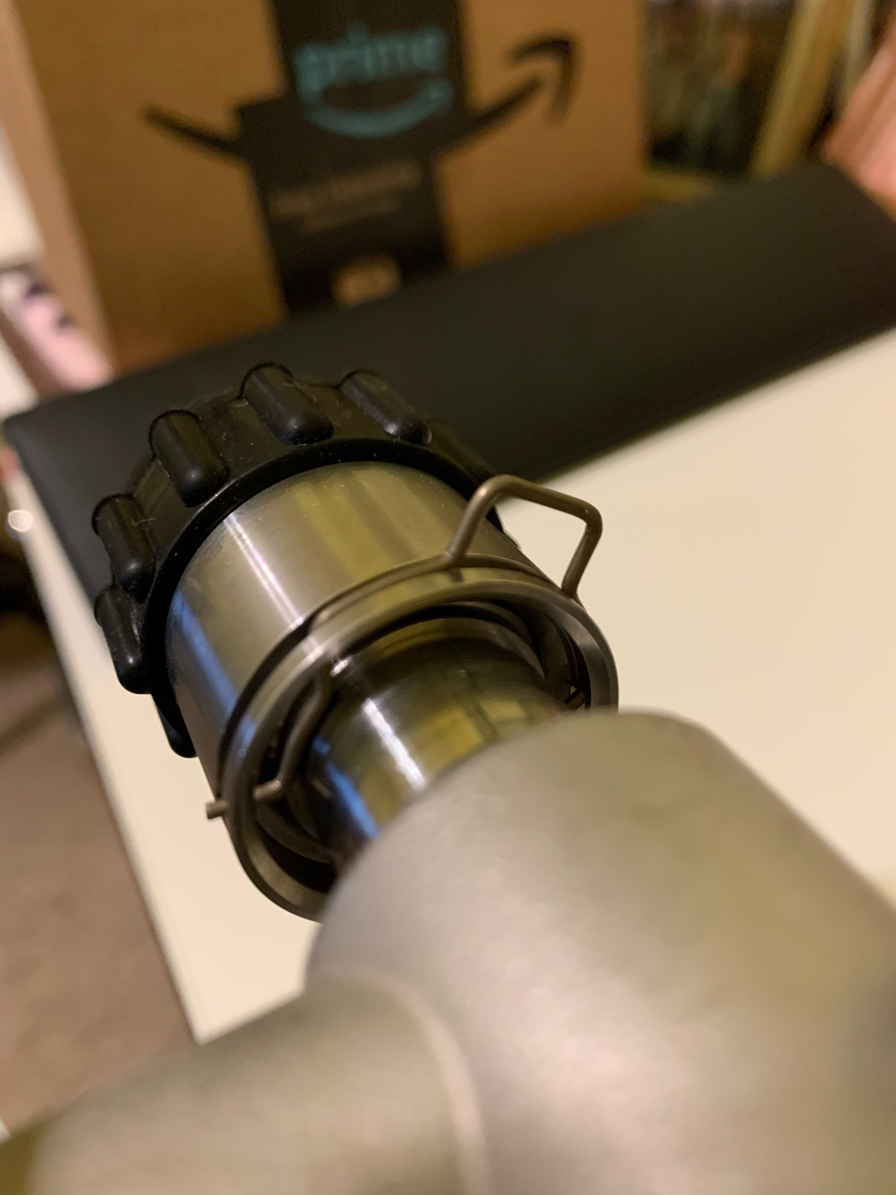
Sure, see below from what I sent Blichmann over a year ago now. Just emailed them again but I think their support is ghosting me after promising replacements so I wouldn’t return them…and now am past any return window. In the first pic the top is the g2 linear flow valve and the bottom is the valve on the riptide pump head. Note the small ridge on the front edge of the bottom one that the clip catches on (as illustrated in the second picture) and stops the valve from turning. The flow valves I received do not have this ridge so the clips just hit the threads on the valve and don’t stop you from turning it until it pops off (and then the worst part is you can’t screw it back on unless you remove the clip because with horrible irony the “safety“ clip does not prevent removal but DOES prevent re-securing the knob on the threads).
image1.jpeg
image2.jpeg
 
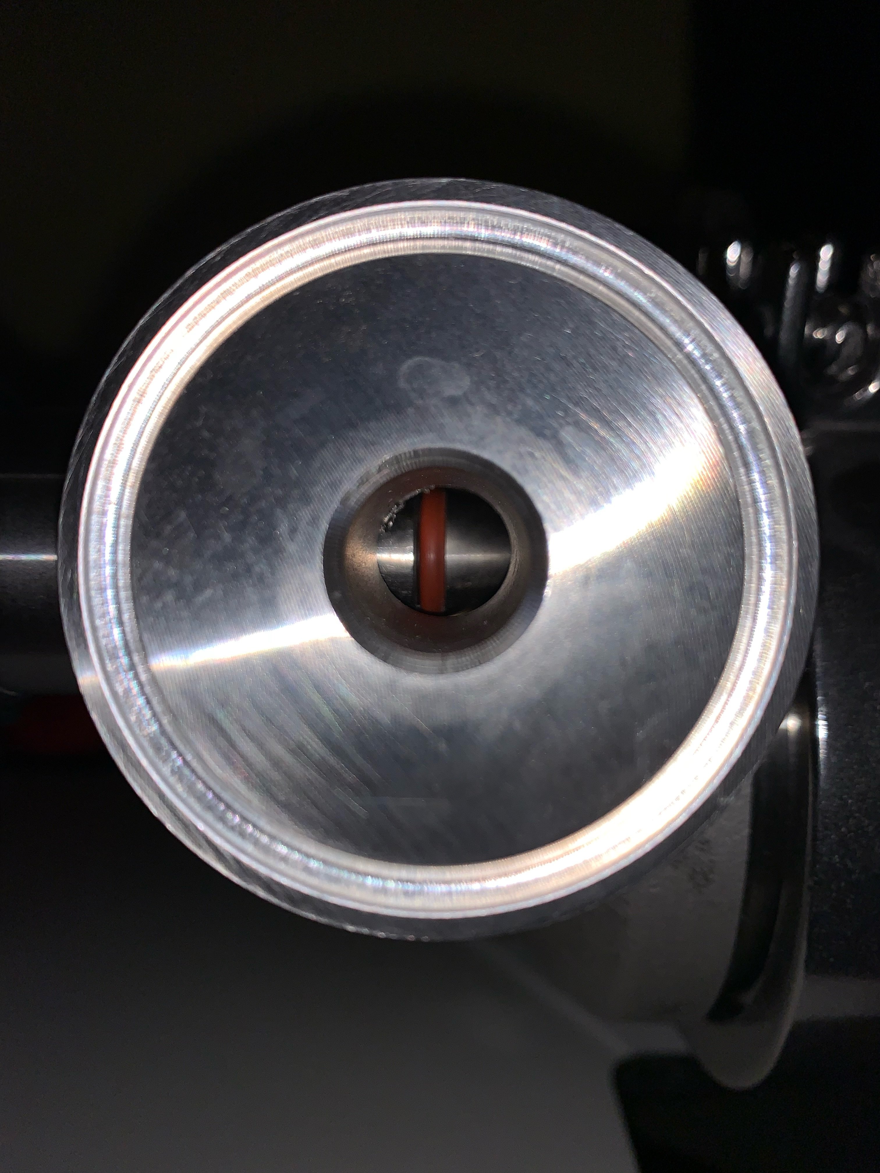
This pic is of the riptide pump head with the valve opened to where the clip hits the ridge to show how much of the “bullet” edge is still in the flow path. It makes it look more closed off than it really is, but flow would work fine in either direction - however perhaps more ideal if flow faced the bullet of the valve.
1689044482099.jpeg
 
Excellent, thanks much.
So on the pump version, you have to remove that clip to get the knob out to clean? And on the other valve, what purpose does the clip serve? Pressure/resistance?

I’ll go ahead and get a couple and see if they look any different. If they don’t have the ridge, I’ll be sure to let them know as well.
 
The one on the Riptide the clip serves to stop the valve from being unscrewed too far and removed, basically stopping the knob from unscrewing past their designated "full open" position. On the TC linear valve version, the flawed design means the clip has absolutely no purpose except for to get in your way when trying to close the valve after you've accidentally opened it too far (either you have to remove the clip or if you try to force it the clip will get caught in the threading). In my testing, even with the clip removed and unscrewed all the way, it still requires a solid pull to remove the valve knob/stem and it did not seem like brewing pump pressures would force them to pop out, nor did I have leaks. Am contemplating just removing the clip entirely next brew - but really wish they had the design right where it would stop the valve at the "full open" position.
 
Without seeing one in hand, and going by videos is looks like when you get to “fully open” it’s the resistance of the O-rings that stops it from coming out on the non-pump version. If the threads are completely disengaged at that point then the first thread would act as a sort of stop for the clip as long as you weren’t turning it. Do you think if a small V-groove were filed into it (in the same area as the little shelf on the pump version) the clip would hit a detent that might be enough to stop it but also allow you to screw it back without removing the clip? It could also be a U shaped channel as long as the clip has enough force to engage it. Just thinking out loud here.

Late Breaking News: I emailed Blichmann to ask about whether the valve works in either flow direction. They said it only works one way! That’s a little surprising to me. While the design looks like flow might be more optimal one way, I can’t see any reason why it wouldn’t work the other way.
 
Last edited:
What’s interesting is that the valves I got (with Bobby’s BIAB system) had no clips at all.
Maybe they pulled the clips off of them to stop people like me from asking for "working as originally designed" models. No way they would offer free replacements for an entire production run. They apparently weren't aware of the issue until I brought it up. Sigh. My desire for proper working products is conflicted with my appreciation of their generally good design and uniqueness. The reality is they work fine and don't push off with pump pressure so the clip isn't needed.
 
Late Breaking News: I emailed Blichmann to ask about whether the valve works in either flow direction. They said it only works one way! That’s a little surprising to me. While the design looks like flow might be more optimal one way, I can’t see any reason why it wouldn’t work the other way.

Huh? There is no reason why it wouldn't work in both directions.
Right... see that visible gap in my photo? Water/wort will pass through there. Guarantee it :) Maybe more turbulence if used backwards (which - who cares about), but this is not a one way fluid gate, it's an open/shut valve. You could use in either direction.
 
Huh? There is no reason why it wouldn't work in both directions.
Believe me, I was kinda dumbfounded by the response. I even asked if they could explain to me why it wouldn't work in both directions.
They responded "It will not work because of how the seals and the valve are set up. There wouldn't be a way to seal it up against the kettle wall plus the linear portion of the valve would not work properly."
In my application, which is following pretty close to your ebiab setup @Bobby_M , it would be screwed into the kettles female NPT couplings using the male NPT arm of the valve. Then I'd use the valves female NPT to connect a quick release fitting / silicon hose to the pump. I was going to respond but realized I would likely be snarky and I gave up. I'm still undecided on what I'll do. My main reason for the linear valve was ease of cleaning. 2 piece aren't bad once correctly opened, three piece are heavier and have lots of parts disassembled. I'm also wondering on the flow rate vs regular ball valve?
Sorry OP, I didn't mean to hijack.
 
Oh, maybe it's not a problem with letting flow through, as much as a problem with blocking flow. The seals are on the movable part, that slides forward into the cylinder. It might not seal between the "output" and the threaded side with the knob. Maybe it leaks if you turn it off and apply pressure on that side.
 
Oh, maybe it's not a problem with letting flow through, as much as a problem with blocking flow. The seals are on the movable part, that slides forward into the cylinder. It might not seal between the "output" and the threaded side with the knob. Maybe it leaks if you turn it off and apply pressure on that side.
The rear seal never loses seating until the knob/bullet portion is forcibly pulled from the rest of the valve, regardless of how far it is unscrewed, so that seal is intact. Flow in one direction or the other would not make a difference considering it manages to not leak when under pump pressure. It is possible that hop matter might be more likely to clog if the flow didn't get pushed in over the bullet nose of the valve but even likely wouldn't make a big difference. Same amount of gap in the valve opening to allow flow either way should yield the same results. @Komodo what's the use case for reversing flow?
 
In my application, I would be mounting the male side of the valve to my kettle wall female coupling. So, most of the time I would actually be using it in “reverse mode”. Underletting mash would be a case where I would use it in the other direction. Also, as my set up is basically @Bobby_M setup, the pickup tube valve would be reversed, but then for the recirc/whirlpool valve, it would be reentering the kettle the “correct” direction!
 
Believe me, I was kinda dumbfounded by the response. I even asked if they could explain to me why it wouldn't work in both directions.
They responded "It will not work because of how the seals and the valve are set up. There wouldn't be a way to seal it up against the kettle wall plus the linear portion of the valve would not work properly."
In my application, which is following pretty close to your ebiab setup @Bobby_M , it would be screwed into the kettles female NPT couplings using the male NPT arm of the valve. Then I'd use the valves female NPT to connect a quick release fitting / silicon hose to the pump. I was going to respond but realized I would likely be snarky and I gave up. I'm still undecided on what I'll do. My main reason for the linear valve was ease of cleaning. 2 piece aren't bad once correctly opened, three piece are heavier and have lots of parts disassembled. I'm also wondering on the flow rate vs regular ball valve?
Sorry OP, I didn't mean to hijack.

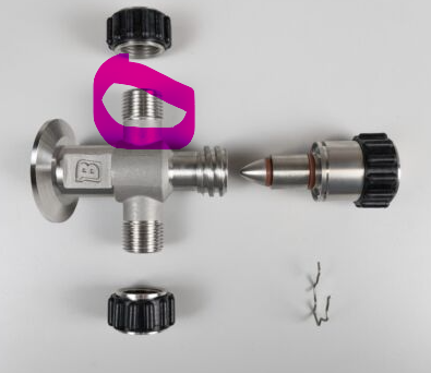
The only thing I can think of is that they made the NPT ones specifically to work as a bulkhead on one end and they have tunnel vision on that. I haven't specifically checked, but it's possible the female side is BSPP thread rather than NPT. In their design, the male threaded end of their bulkhead could also be BSPP loose thread and the assembly would work as designed without allowing an male NPT to thread in. I can easily check tomorrow.

One reason I'm speculating is that I know for certain these male threads on the aseptic valve are BSPP
1689132440063.png


Bobby
 
You know how I know Blichmann didn't really think their answer through? They use the linear flow valves on their own systems as the input to their whirlpool returns. That's why the flow direction doesn't matter but they absolutely were thinking about how the one end is made to attach to the kettle side (physically).
 
I’m guessing you may be right about the female BSPP since it’s clearly designed as a bulkhead and the valve has the sealing Oring. It’s odd they sell the male bulkhead insert separately and don’t mention BPSS thread, and the website lists the valve as 1/2” NPT although they don’t indicate whether that’s the male or female end. I guess I assumed both.
 
dzimm27: If your goal is to effect a tempature drop from 190 to 145 during mash, have you by any chance tried just tried circulating your 190° wert without the CFC in the loop to see how much heat all that pretty stainless steel hardware will shed into the ambient environment? It might be that a box fan blowing on your equipment will provide the temperature drop you need in an acceptable time frame. Try with a load of water for a simple test.
 
The only thing I can think of is that they made the NPT ones specifically to work as a bulkhead on one end and they have tunnel vision on that. I haven't specifically checked, but it's possible the female side is BSPP thread rather than NPT. In their design, the male threaded end of their bulkhead could also be BSPP loose thread and the assembly would work as designed without allowing an male NPT to thread in. I can easily check tomorrow.

One reason I'm speculating is that I know for certain these male threads on the aseptic valve are BSPP


Bobby
I’ve been back and forth with Blichmann a couple more times. This was like pulling teeth, but finally got: “The threads are 1/2 inch NPT both male and female.”

Since all their responses have either been wrong or almost resistant(?), I don’t even trust that answer. Did you ever check one of the valves @Bobby_M?
 
Back
Top