YAY!
Brilliant, thank you. I understand now that the voltage measurement is the two lines in to the meter, and the amperage measurement is through the transformer loop. I assume then that since I'll have the meter on the 240V circuit only, that all of the 120V Amperage is out of scope. If I understand all these components correctly, the biggest draw on the 120V circuit is going to be my pump, and that thing draws a max of 1A so I'm really not going to be measuring much there anyway. How am I doing here?
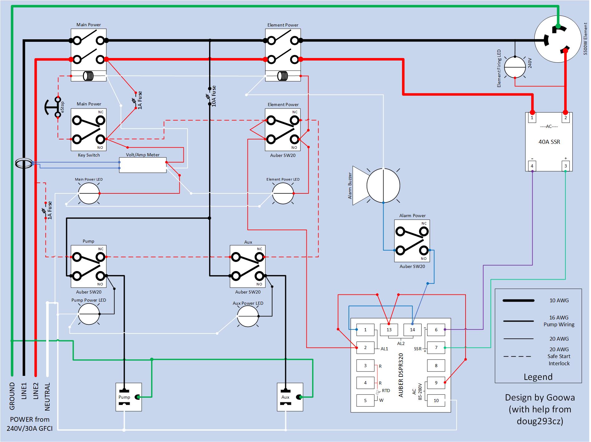
The current sensing transformer is on the black hot line, so it will measure the element current, pump current, and aux current. Element current goes thru both the black and red hots. Pump and aux current go thru the black hot and neutral. The only currents that won't be measured are the contactor coils, PID, and alarm currents, which should total less than 0.5 amp.
I based my diagram around similar ones you created, with the safe start diagram being from this post:
https://www.homebrewtalk.com/forum/...ectrical-diagrams.382286/page-23#post-7848752
You caught me. I didn't catch the problem in that design. I need to go back and see if I can figure out why I did it that way in that design. I also need to put a better design in that thread.
I also missed the post below it which has a very similar diagram to the one you posted in your example above. But yep, I see that the dotted line jumpered over the two contacts on the element switch would have the EZBoil turned on when all of the interlocked switches are off (as well as even the main power switch is off). Also, the dotted line would power the connection to the meter and the main power lamp in the same scenario.
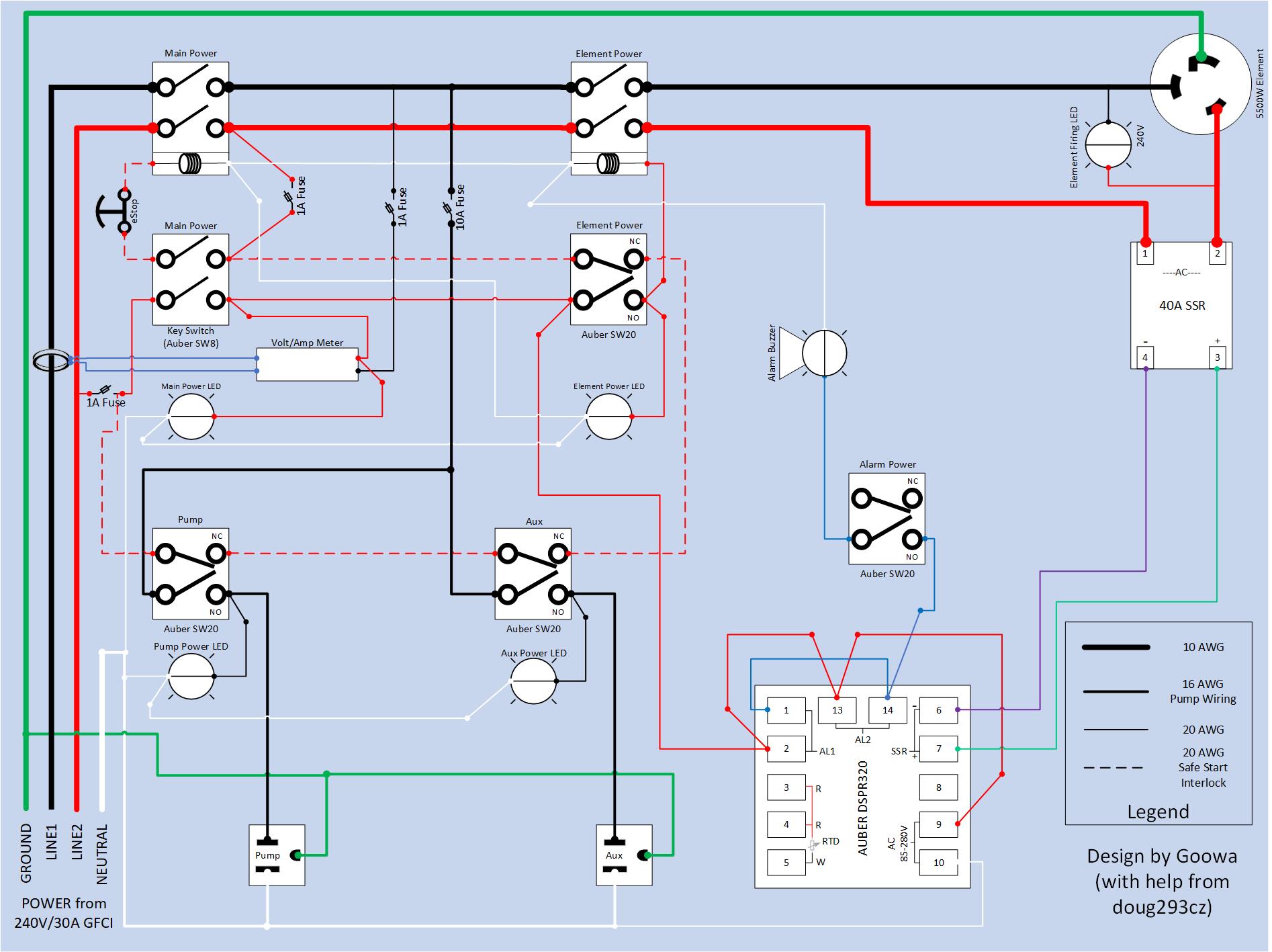
I touched up the diagram again (edit: attached it)
Looking at the latest example you provided there is no 1 amp fuses between the 10AWG line2 and the 20AWG line to the element switch. I thought any time you change wire sizes you should protect the smaller wire with a fuse?
You caught me again. The 20AWG black wire should be fused. It was an oversight, and I will go back and correct. Sometimes whether to fuse or not is a judgement call. For example, you often plug appliances into 15A or 20A outlets with wires not rated for that current. Wires inside structure walls are more of a risk for over heating than are wires in the open air. Inside an enclosure, it is often acceptable to use short runs of unfused wire to devices that are intrinsically current limited. Also, very fine wires (in enclosures) can act as fuses in the case of a short, without creating enough heat to start a fire. So, most designs don't fuse at all wire reductions, but only where there is a lot of downstream wiring. Another consideration is how many connections are in the unfused net, as fewer connections mean fewer possible points of failure, as do shorter wire lengths.
Also, see ho wi shared one 1 amp fuse between the interlock and the power to second pole on the main power switch? Is that kosher? If not, I'm going to have five fuses holders hanging out of my panel. :/
I haven't been able to come up with a reason why that would be a problem.
Thank you for your help!


![Craft A Brew - Safale S-04 Dry Yeast - Fermentis - English Ale Dry Yeast - For English and American Ales and Hard Apple Ciders - Ingredients for Home Brewing - Beer Making Supplies - [1 Pack]](https://m.media-amazon.com/images/I/41fVGNh6JfL._SL500_.jpg)


")