Yet another DYI Plato scale

Homebrew Talk - Beer, Wine, Mead, & Cider Brewing Discussion Forum

Help Support Homebrew Talk - Beer, Wine, Mead, & Cider Brewing Discussion Forum:

This site may earn a commission from merchant affiliate links, including eBay, Amazon, and others.

mper

Supporting Member
HBT Supporter
Joined
May 24, 2020
Messages
303
Reaction score
93
I've been building a scale for my keezer based on cheap hardware. There are quite a few projects on Github that shows how to build a simple scale on HX711 and load cells. But what I found that those are not really that stable over time and most software was not accurate enough for my needs. On my first builds it could shift 2 lbs over a 24 hour period which is not good if you want to implement advanced features. There are a few other projects that will provide excellent data quality like KegCop but I didnt want to have any sensors on my beer lines (and those flow sensors was really expensive in Sweden, more than 25 times more expensive than load cells.

I ended up with this setup so far: ESP8266, 2 x HX711 + Load Cells and 2 x 0.96" OLED displays. 3D printed scale bases. One build supports 2 scales.

I'm quite happy with my build so far since I think I managed to fix a lot of the stability issues. I have not really put that much efforts in to the documentation as with my other projects.

So my question here is if there are anyone that is interested in this type of build and would help to give feedback in order define the future path of the project.

Would you be interested to build this ?
What features would you like to have ?


These are the features that I have done so far:
* WIFI Enabled,
* Web based configuration
* Simple scale calibration via web interface (3 steps)
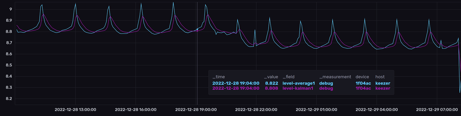
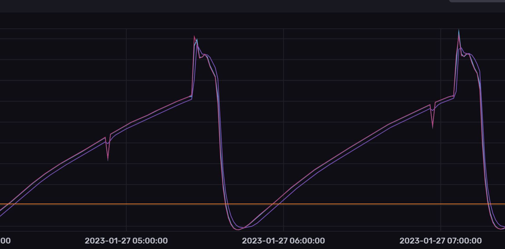
* Stable level detection (will filter out sudden changes of the hx scales)
* Ability to detect the pour of a beer (min 10 cl)
* Histogram over the last level changes and pours.
* Push changes to brewspy (pour and keg volume)
* Get brew/beer data from Brewfather (Beer name, abv, fg, ebc, ibu)
* Choose size of a glass of beer (so that the weight is correctly converted to remaining glasses)

The project can be found here;
https://github.com/mp-se/kegmon
 
Here is a short animation that shows the user interface as it looks today.

Kegmon2.gif
 
I'd been messing with scales as part of a different hobby - same issues here though: Interference (vibrations) and drift on the load cells. Beer was always in the back of my mind (as it should be!) and I'd considered solutions there that could apply here. I'm curious if you are using these (or other) methods:
  1. Keep the load < 50% of the load cell max capacity
  2. Filter out abrupt changes (possibly re-zero as a result) - this to prevent issues when jostling the kegs or kegerator, maybe the random floor-stomp
  3. Filter out slow changes - this to get rid of creep over time.
Somewhere in the middle of these "filters" is an envelope of "reasonable changes," such that which would indicate a pour being drawn.
I also noticed the drift and variations over time and it has been a lot of trial and error. I used the same clk signal for my two scales but that caused a lot of interference, so having those separate is a must.

1, yes i use 50kg load cells and im using standard cornelious kegs. Max 25kg
2,3, yes i average readings over a minium 20seconds. this handle spikes in values and sudden changes.

ive tried a few methods to get a stable reading and in the current version i use an average reading over at least 20 seconds to determine a stable value. If the deviation is to high (min/max) i restart and check for a new level. This seams to work fine and I can use this to detect a glass beeing poured if the level is dropping.

im currenly testing and gathering more data to see what can be improved.

im looking for other options but this has been the best so far. Tried a kalman filter as well but that is to slow to follow a change in level (might just need to tune the filter).
 
Tried a kalman filter as well but that is to slow to follow a change in level (might just need to tune the filter)
It's interesting you mention that - it's one of the filters I tried. I left the effort thinking that the filter (at least how I was messing with it) needed a much faster sample rate than I was able to achieve. I never did figure it out completely but I believe the (my?) lack of being able to apply a fast enough sample rate consistently without a dedicated interrupt. A single-core processor that's busy doing other things can't really be counted upon for microsecond accuracy, or at least that was my theory. It's possible using an ESP32 with it's second core could help with a dedicated interrupt (if you turn off WiFi for that sampling period.)

But, I kept coming back to "it's just beer" and never solved it all the way.
Reading the hx711 takes quite some time (think i clocked it at 700-800ms) per scale. But as you say the drift is an issue, I like you approach with the flow sensor for accuracy which is always going to be better. My goal has never been to make this as good, just good enough.

The variation of the scale is quite repetitive (raw values + kalman filter) and is probably caused by interference, quality of the loadcells or the temperature variation in the keezer. But it should be possible to filter/smooth out the values....

I have been considering upgrading to an ESP32 to see if that is better. But I guess one of the limitations is the I2C bus speed and how many reads are fetched on the HX711.
 

Attachments

  • scale.png
    scale.png
    139.9 KB · Views: 0
I have been considering upgrading to an ESP32 to see if that is better. But I guess one of the limitations is the I2C bus speed and how many reads are fetched on the HX711.
I'll give you a fair warning that the HX711 and the ESP32 are not on good speaking terms. bogde finally sees to have gotten it working but it's a blocking library so it's got limited uses. The NAU7802 is a better choice there and gives a real I2C - SparkFun has or had a breakout board for it that's handy for breadboarding a solution.
 
I’m using a few HX711s with a esp32 and have never had any issues with them interfacing. My issues are all aligned with drift over time. I’m using them to measure kettle volume, which works fine but after an hour or so I find my tare reading has drifted by enough to make me annoyed. I also suspect that is in part due to using load cells harvested from bathroom scales for weights under 50lbs. They’re really only close to linear in the typical human weight range of 100-200lbs
 
I'll give you a fair warning that the HX711 and the ESP32 are not on good speaking terms. bogde finally sees to have gotten it working but it's a blocking library so it's got limited uses. The NAU7802 is a better choice there and gives a real I2C - SparkFun has or had a breakout board for it that's handy for breadboarding a solution.
Thanks, i will get one of those to try it at least to compare it towards the hx711
 
Here is an example on how the level detection works. I'm currently working on applying a kalman filter on the raw values in order to remove spikes that can occur when reading from the scales. This makes the detection slower but hopefully provides better accuracy.

In the example below you have the raw values in red and the filtered values in blue. The green is the stable level that the software has been detecting. Here I removed 33cl in the first step and 66cl in the second step. It currently takes around 40 seconds to detect a new level and pour. It's half the time without the kalman filter but more errors. Will be interesting to see how this works in my keezer and not just on my desk.

1672997766479.png


Here is an example of a false reading from the scale and the level detection is not affected by it.

1672998157667.png
 
That looks like it’s very effective. Do you use a temp coefficient for temperature based changes?
I've been investigating the impact on temperature on the weight and found that on my scales it has a really small impact. I have between 4-5C temperature in my keezer and the weight changes about 100g. The interference from the compressor seams to have a bigger impact on the signal.

When you did you investigation did you find any examples on formulas for compensating the weight based on temperature ?

I've added the code for compensating for temperature but have not yet found the relationship between weight and temperature....
 
I've been investigating the impact on temperature on the weight and found that on my scales it has a really small impact.
When you use load cells without getting to far up in their max range as you have, it seems that there are lest issues with temp.

The interference from the compressor seams to have a bigger impact on the signal.
You might use a ferrite choke on the leads to see if you get any relief. If you do that remember you are trying to cut down on common mode noise, so wrap all leads together through/around the choke.

When you did you investigation did you find any examples on formulas for compensating the weight based on temperature ?
I didn't save any as being especially interesting, no. When I was messing with it a few years back I noted that there was only a range of temps in which there was any significant change. Rather than doing some cool formula I simply did an "if temp > x and < y then compensate with a ratio, if temp is > y compensate by set value." It was always consistent, anyway.

I've added the code for compensating for temperature but have not yet found the relationship between weight and temperature....
I have seen some load cells that publish temperature compensation graphs with the literature. Lacking that you might have to use a polynomial function like in GravityMon.
 
When you use load cells without getting to far up in their max range as you have, it seems that there are lest issues with temp.


You might use a ferrite choke on the leads to see if you get any relief. If you do that remember you are trying to cut down on common mode noise, so wrap all leads together through/around the choke.


I didn't save any as being especially interesting, no. When I was messing with it a few years back I noted that there was only a range of temps in which there was any significant change. Rather than doing some cool formula I simply did an "if temp > x and < y then compensate with a ratio, if temp is > y compensate by set value." It was always consistent, anyway.


I have seen some load cells that publish temperature compensation graphs with the literature. Lacking that you might have to use a polynomial function like in GravityMon.
Thanks for your input. Always good to get some new ideas and inputs. I will try a ferrite to see if that clears up the signal. To do temperature compensation I would need a clear signal first.

Here are two of my scales and they behave quite differently when the temperature varies.

I did find one discussion on load cells and temperature compensation at a beehive community where there was quite a lot of in-depth discussions and some proposed formulas.

I have implemented the same formula engine as in gravitymon so polynomial could be an option. What I'm concerned with is that it would be hard to find a generic formula and you would need to create a unique one scale build.

I will do some more tests, which also includes drinking and brewing more beer.
 

Attachments

  • temp_variation.png
    temp_variation.png
    132.8 KB · Views: 0
  • temp_variation2.png
    temp_variation2.png
    144.5 KB · Views: 0
I will try a ferrite to see if that clears up the signal. To do temperature compensation I would need a clear signal first.
Another option is to address it at the compressor. AC line filters are semi-expensive, but the components themselves are pretty cheap. Here is an interesting article from a Ham Radio magazine on finding and addressing noise. It does get to actually fixing things around page 40, but the rest is very interesting.

Here are two of my scales and they behave quite differently when the temperature varies.
That's ... yes different. Those tiny wires are pretty sensitive to noise and self-induced current. You could look at routing them exactly them same, or using some shielding on them.

I did find one discussion on load cells and temperature compensation at a beehive community where there was quite a lot of in-depth discussions and some proposed formulas.
Yep, that's where I was messing with it a bit.

What I'm concerned with is that it would be hard to find a generic formula and you would need to create a unique one scale build.
I think GravityMon just plugs your derived formula into it's processing - do it is custom for each installation.

I will do some more tests, which also includes drinking and brewing more beer.
Now there's a fantastic idea!
 
I've just released a new version of the firmware for this project.

https://github.com/mp-se/kegmon/releases/tag/v0.5.0
Some of the new features:
  • Optional build with Async webserver (regard this as experimental)
  • Level detection has been refactored and I added a Kalman filter to remove the worst interference.
  • Added option to do temperature compensation of load cells in software (formula still to be concluded). Requires a temperature sensor close to the load cells.
  • Added integration with Home Assistant (via MQTT)
  • Added graphs in web interface that shows the stability (requires the web browser to be open, data storage and rendering is done in the browser)
  • Added some advanced configuration options to define params used by the level detection algorithm.
If you want to try out the software you can load this to a plain esp8266 without any sensors. You can experience the UI but you will not get any data.
 
Was this done with just an MQTT push? What did you use as a reference for this?
There is a feature in Home Assistant called MQTT discovery. If you put a standard message on the broker then HA will automatically create a sensor for that.

https://www.home-assistant.io/integrations/mqtt#mqtt-discovery
This is an example of what I use to create a beer sensor with some value and attributes:

Code:
homeassistant/sensor/${mdns}_beer${tap}/config:
{\"name\":\"${mdns}_beer${tap}\",\"state_topic\":\"homeassistant/sensor/","${mdns}_beer${tap}/state\",\"json_attributes_topic\":\"homeassistant/","sensor/${mdns}_beer${tap}/","attr\",\"unique_id\":\"${mdns}_beer${tap}\"}

homeassistant/sensor/${mdns}_beer${tap}/state:
${beer-name}

homeassistant/sensor/${mdns}_beer${tap}/attr:
{\"abv\":${beer-abv},\"abv\":${beer-abv},\"ibu\":${beer-ibu},\"ebc\":"${beer-ebc}}
 
@mper I'm 6 months into my HomeAssistant journey and your post has just opened out a whole new world of exploration, integration and further "smart homing". Time for some reading and testing :thumbsup:. GravityMon and BrewBubbles integration here we come, but next week unfortunately.
 
@mper, Love your integration. Thank you. Better than handing out the dough for a Platto. Is there anyway you can add the option into KegMon for a BME280? The BME's are a little more accurate. Also i have them :)
 
@mper, Love your integration. Thank you. Better than handing out the dough for a Platto. Is there anyway you can add the option into KegMon for a BME280? The BME's are a little more accurate. Also i have them :)
might be possible, depends if it can be run on the same pins as the oled displays. i can give it a try, i think i have one of those somewhere
 
might be possible, depends if it can be run on the same pins as the oled displays. i can give it a try, i think i have one of those somewhere
Thank you. I personally am not running the OLED, but understand. just have it in Home Assistant via MQTT.
 
Thank you. I personally am not running the OLED, but understand. just have it in Home Assistant via MQTT.
After doing some more research this is probably not feasible. The i2c bus that the BME280 is using was not designed for longer distances, the recommendation is to have as short cables as possible (less than a meter / few feet) so putting that in a scale base is probably not a good idea. Longer cables might work but would require a lower frequency = slower communication.

I have been planning to add support for the standard DS18B20 sensor which will work over long distances. So other similar devices has a better chance of working.

When I look at the datasheets for the various sensors it looks like all of them have a accuracy of 0.5C but the BME will have lower accuracy below zero degrees (1.5C accuracy) while the others maintain the accuracy.
 
Nice to find this thread. I has been experimentig with hx711 and load cells to weight the fermenter.
I want to find the delta as co2 exit to calculate the amount of alcohol and then the Plato.
As you mention time drift make it almost impossible.
 
After doing some more research this is probably not feasible. The i2c bus that the BME280 is using was not designed for longer distances, the recommendation is to have as short cables as possible (less than a meter / few feet) so putting that in a scale base is probably not a good idea. Longer cables might work but would require a lower frequency = slower communication.

I have been planning to add support for the standard DS18B20 sensor which will work over long distances. So other similar devices has a better chance of working.

When I look at the datasheets for the various sensors it looks like all of them have a accuracy of 0.5C but the BME will have lower accuracy below zero degrees (1.5C accuracy) while the others maintain the accuracy.
Ok. Thanks for the research. I do have my setup a little different all in the fridge. I’ll pick up a DHT22.

Question, I know you just implemented MQTT and works great, it reports in litres. Is there a way to get it to report pints or Oz? Or shall I covert this on HA side? Thanks again!
 
Ok. Thanks for the research. I do have my setup a little different all in the fridge. I’ll pick up a DHT22.

Question, I know you just implemented MQTT and works great, it reports in litres. Is there a way to get it to report pints or Oz? Or shall I covert this on HA side? Thanks again!
Good question, it would not be to difficult to push the data in the format selected on the device. Internally I use C and Liters as the internal so this was just the easy way to go.

I have not investigated if HA will handle the conversion for you or it just used the format of the sensor, do you know ?

Feel free to add this as an enhancement on github for the next release if you want me to fix it when pushing.
 
Nice to find this thread. I has been experimentig with hx711 and load cells to weight the fermenter.
I want to find the delta as co2 exit to calculate the amount of alcohol and then the Plato.
As you mention time drift make it almost impossible.
I have not noticed that there is much drift when I have done long term tests. My main issue is interference from the fridge and temperature that causes the level to change in intervals.

I dont know if the load cells have the needed accuracy for your applications, what is the difference in weight that you are trying to detect ?

You are probably better off trying to measure the gas that is exiting using some kind of flow sensor. I've been tinkering on another project for measuring pressure in a fermentation vessel but I haven't worked on that for a while.
 
What do you guys mean by time drift? Inaccuracies of measuring over time? What causes this? Software or hardware issue?
 
What do you guys mean by time drift? Inaccuracies of measuring over time? What causes this? Software or hardware issue?
Typically the level will change over time, for example it can drop over time. This is most often hardware related and due to poor quality in the load cells. A cheap scale will typically do a zero leveling when starting up and turn off over time. These scales are most reliable that way, which is not really the case here... I have noticed that temperature and humidity will have an effect but it quite stable over time. I try to compensate for some of these issues in the software which is a challenge.
 
I have been running Kegmon v0.6.0beta1 with ESP32-s2 for a few days now. Stable and no big issues.

When I first built the unit with D1 mini, I connected VDD on DHT22 to 3V3 according to the schematic at that time.
Yesterday, I changed DHT22's VDD connection to JP1.5/D6 as in the latest schematic.
ESP32-s2 did not recognize any temp sensor unless I flashed firmware via Web interface again. Then it worked for some time before temp sensor was gone again (Web interface/ MQTT).
Today, I connected VDD back to 3V3. All ok.

I wonder if the voltage level from ESP32-s2 I/O's is on the edge to be too low for the DHT22 (Rated 3.3 - 6V). Sorry, forgot to measure.
DHT22 current (1-1.5mA) should be ok.
Any voltage differences on the I/O ports for D1 mini vs ESP32-s2 maybe?
 
I have been running Kegmon v0.6.0beta1 with ESP32-s2 for a few days now. Stable and no big issues.

When I first built the unit with D1 mini, I connected VDD on DHT22 to 3V3 according to the schematic at that time.
Yesterday, I changed DHT22's VDD connection to JP1.5/D6 as in the latest schematic.
ESP32-s2 did not recognize any temp sensor unless I flashed firmware via Web interface again. Then it worked for some time before temp sensor was gone again (Web interface/ MQTT).
Today, I connected VDD back to 3V3. All ok.

I wonder if the voltage level from ESP32-s2 I/O's is on the edge to be too low for the DHT22 (Rated 3.3 - 6V). Sorry, forgot to measure.

DHT22 current (1-1.5mA) should be ok.
Any voltage differences on the I/O ports for D1 mini vs ESP32-s2 maybe?
You can run the DHT22 on VCC as well, but I had issues that it stopped working and I lost the temperature readings, if its connected to D6 I can try to power on/off the sensor and get it up and running again. I also read that the sensor should not be read too often so I also changed the interval when the sensor is read. I have not confirmed if the read interval was the reason or not.

Both the ESP8266 and ESP32 should deliver enough current on the GPIO to power the temp sensor. The S2 can deliver 40mA which I think is twice the power of the ESP8266.

Its interesting that you have issues with powered by the D6 pin, i have not converted my build to ESP32S2 yet but I plan to do that.

It could be that the power drops too much if the cable to the temp sensor is long. I will check that when I convert my build. I have only tested it on my breadboard setup with the S2.

I have added support for DS18B20 in the beta 1 so that might be a more stable option for temperature and long distance, but you will loose the humidity data then.
 
I have been running Kegmon v0.6.0beta1 with ESP32-s2 for a few days now. Stable and no big issues.

When I first built the unit with D1 mini, I connected VDD on DHT22 to 3V3 according to the schematic at that time.
Yesterday, I changed DHT22's VDD connection to JP1.5/D6 as in the latest schematic.
ESP32-s2 did not recognize any temp sensor unless I flashed firmware via Web interface again. Then it worked for some time before temp sensor was gone again (Web interface/ MQTT).
Today, I connected VDD back to 3V3. All ok.

I wonder if the voltage level from ESP32-s2 I/O's is on the edge to be too low for the DHT22 (Rated 3.3 - 6V). Sorry, forgot to measure.
DHT22 current (1-1.5mA) should be ok.
Any voltage differences on the I/O ports for D1 mini vs ESP32-s2 maybe?
I swapped my esp8266 to a esp32s2 and I got the same result as you, no temp sensor. I will do some more tests during the weekend to figure out if this is the power level or data signal from the sensor. There is a recommendation to add a pullup resistor (5k) the data signal that might solve the problem.
 
I swapped my esp8266 to a esp32s2 and I got the same result as you, no temp sensor. I will do some more tests during the weekend to figure out if this is the power level or data signal from the sensor. There is a recommendation to add a pullup resistor (5k) the data signal that might solve the problem.
From datasheet, there seems to be a possibility to define pullup/down in software for GPIO pins. Maybe it is only a "fake" pullup.

I did some tests yesterday. Connected AM2302 (DHT22) with short leads to the replaced D1 mini. Unfortunately, I do not have any spare ESP32-s2 at the moment, which would be more correct to test with.
D6 voltage on the D1 mini was negligible lower than the 3V3 pin.
On the scope, everything seemed to be fine.

According to your build description, pin8/Brown on the Cat6 is DHT22 data. Pin7/Brown-White is unused. Instead of floating, maybe it is better to connect it to DHT22 GND (Pin1/Orange-White)?
I have to check my layout if I have already done this.
Btw: My Cat6 cables are 1.5m round UTP.

I read somewhere that the 4-pin AM2302 already has an inbuilt pullup(?) Some also recommends adding a 100nF, and maybe a 10nF cap close to the DHT22 to fight noisy signals.

According to misc forums, it looks like the DHT22 is quite unpredictable. A good idea you added DS18B20 as an alternative. Rock solid if you are able to get hold of original Maxim ones :)
I've tried the GPIO pin configuration on the ESP32 and none of them seams to work when I have long cables. I measured the output on my board and it was 3.3V which is the same as on the ESP8266. I also tried adding a 4.7k pullup to the data signal without success.

Connecting the brown white to GND is a good idea, I will update the build instructions. Could not hurt.

I'm building an extra base and I will use the DS18B20 sensor on that instead to see if that work better with the s2. I've also read that the DHT22 is an unstable sensor so I might be better to move away from that one. I have had issues, which is why I added the possibility to reset it and get some readings. For the temperature correction to work I need to have a stable temperature reading.
Is the DS18B20 connected the same way:
GND ---> GND
VCC ---> 3V3
DQ ---> D7
And a 4k7 between DQ and VCC "as usual" ?
 
Back
Top