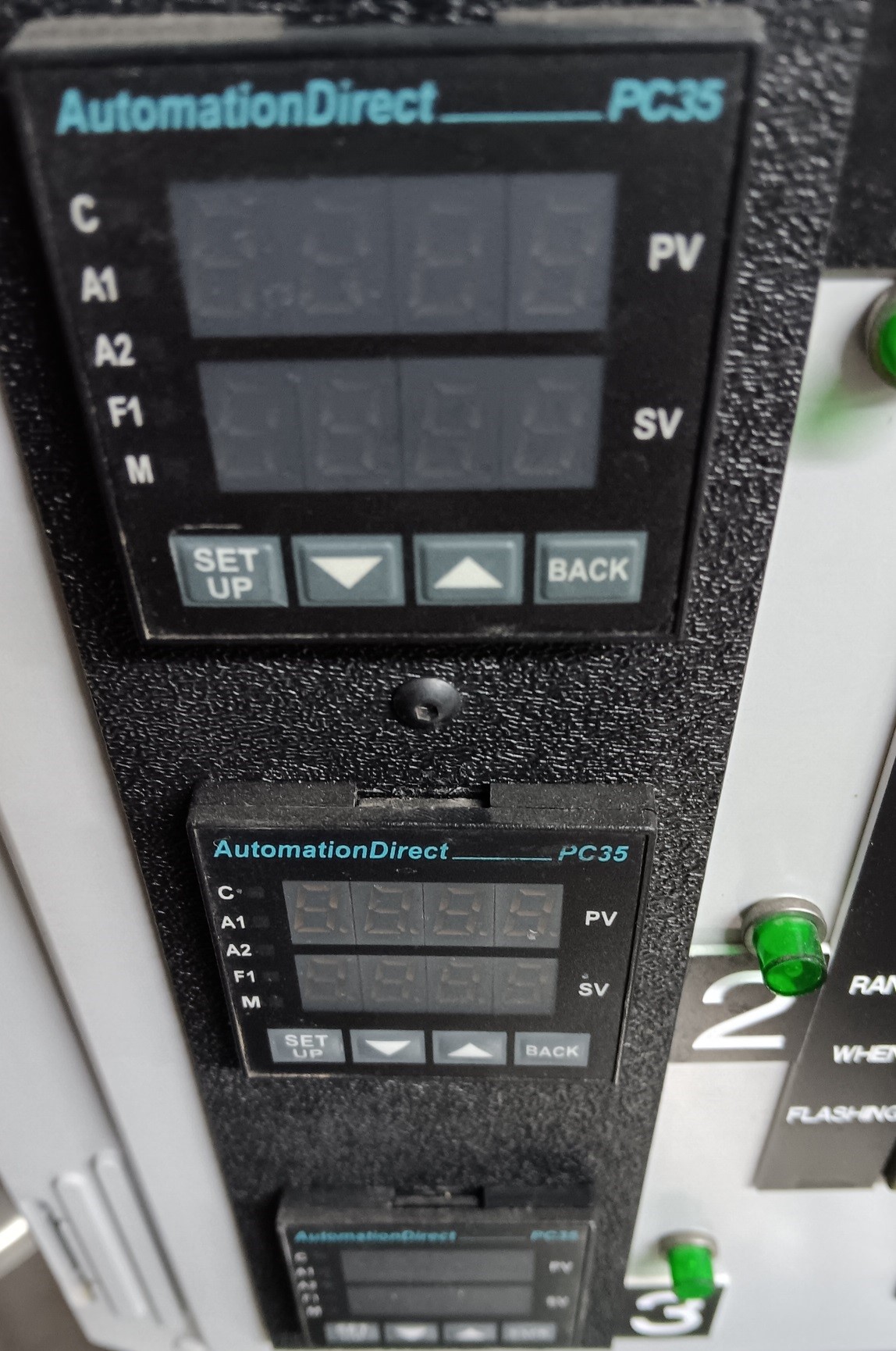
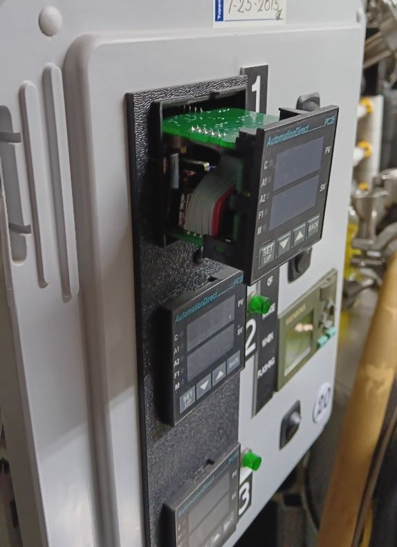
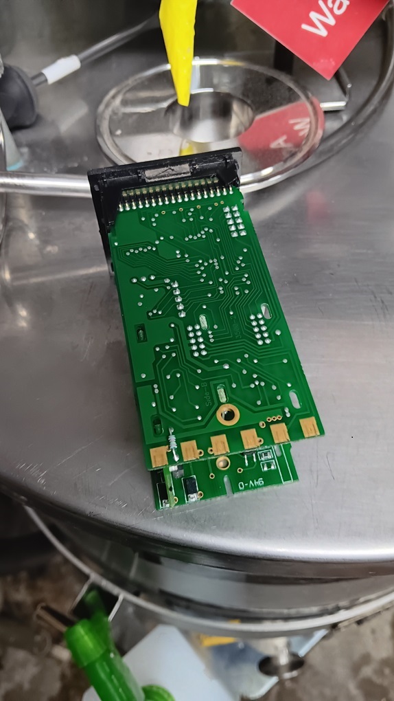
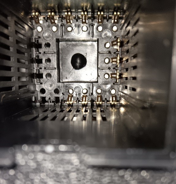
I'm finally getting back to brewing after nearly six years, so I'm putting everything back together. I plugged in the control panel, pushed all the buttons (the pump works!), but the PID will not turn on. I opened the box and checked all the connections, and they're all secure, no apparent shorts, all the fuses are fine. I did notice a low hum from the circled part (second picture) when I turned on the heating element, but it goes away when I turn off the heating element.
How can I figure out why the PID isn't turning on? Or should I just replace all the essential bits and call it a day? It's been so long since I built this that I don't even remember what all the parts are called or where I bought them!


How can I figure out why the PID isn't turning on? Or should I just replace all the essential bits and call it a day? It's been so long since I built this that I don't even remember what all the parts are called or where I bought them!


![Craft A Brew - Safale S-04 Dry Yeast - Fermentis - English Ale Dry Yeast - For English and American Ales and Hard Apple Ciders - Ingredients for Home Brewing - Beer Making Supplies - [1 Pack]](https://m.media-amazon.com/images/I/41fVGNh6JfL._SL500_.jpg)