2 PID and 1 switch for Firing Elements

Homebrew Talk - Beer, Wine, Mead, & Cider Brewing Discussion Forum

Help Support Homebrew Talk - Beer, Wine, Mead, & Cider Brewing Discussion Forum:

This site may earn a commission from merchant affiliate links, including eBay, Amazon, and others.

handbrewing

Member
Joined
Dec 3, 2014
Messages
20
Reaction score
0
Location
Issaquah
Hi,

I’m looking for a wiring diagram for the below controller setup.

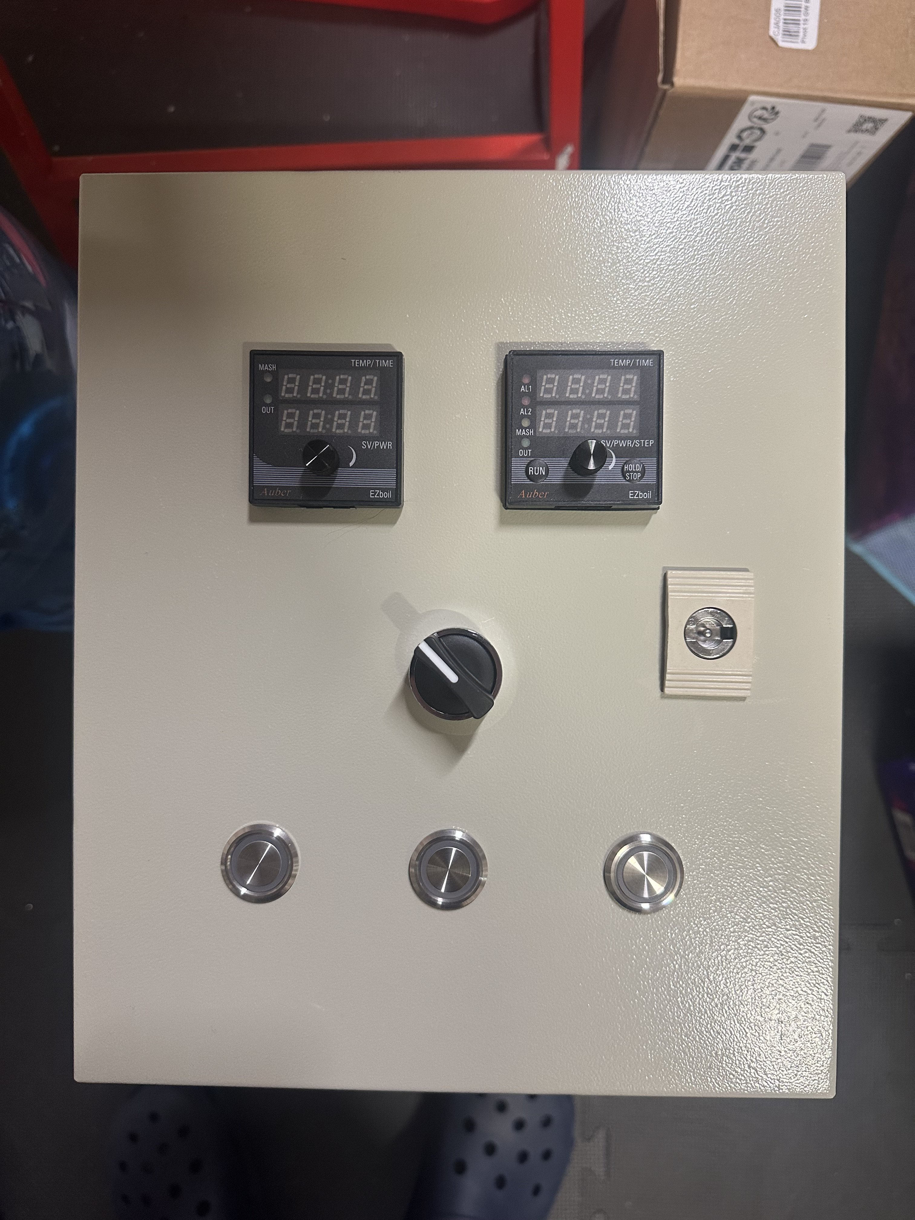
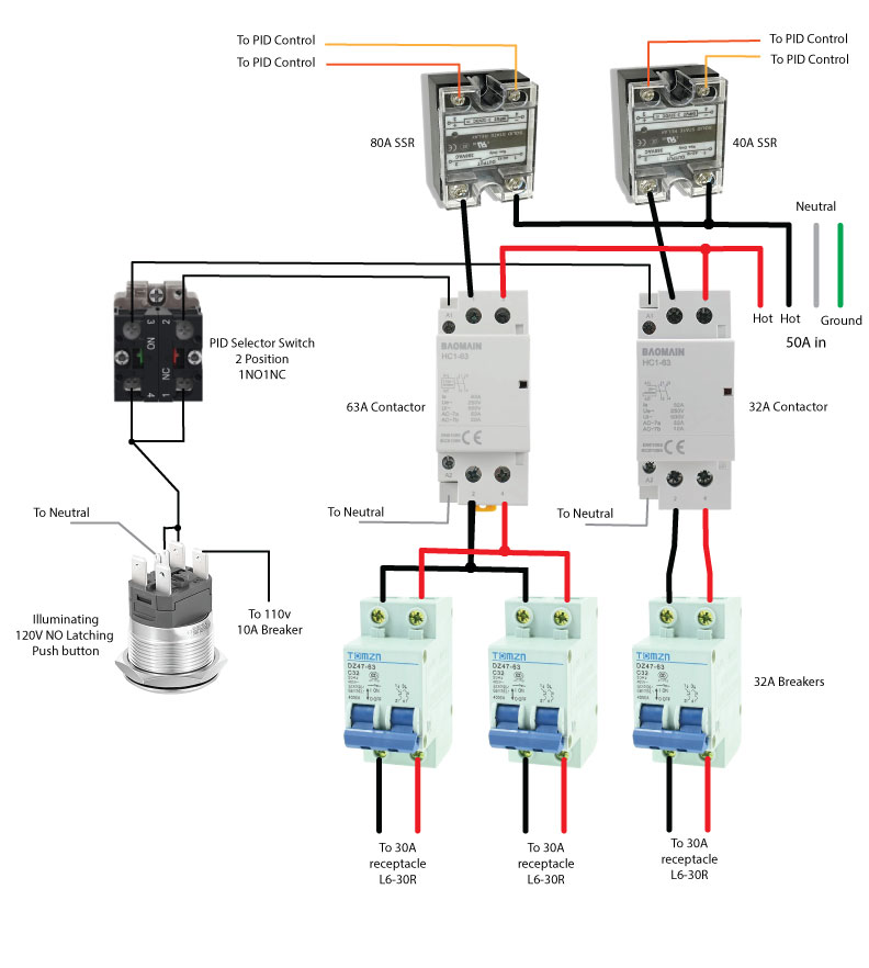
50amp controller with 2 PIDs and 2 SSRs.

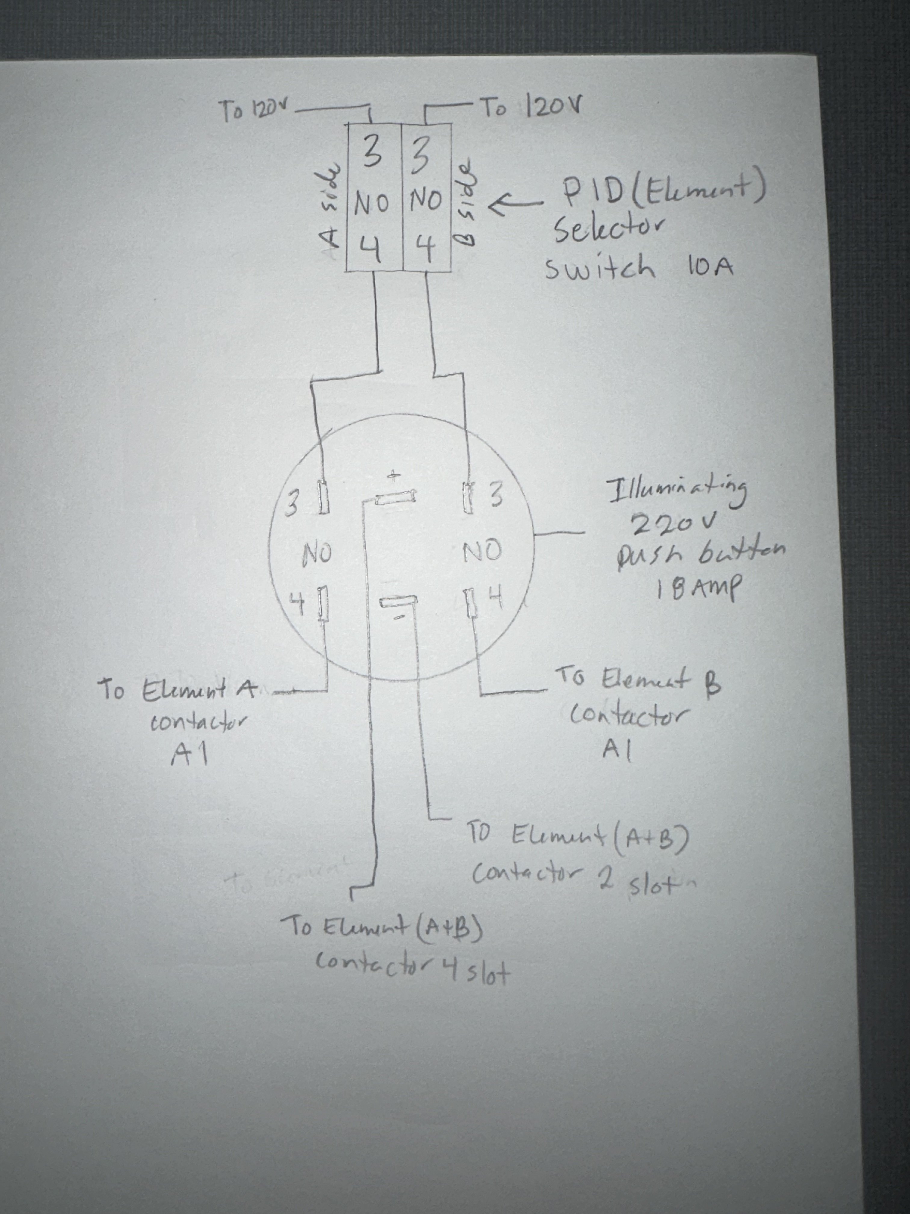
The PIDs will have a selector switch that turns on the PID that’s selected.

I’d like to have a single stitch that fires the elements that has the selected PID on and assigned to its respected elements.

Similar to the Ssbrewtech controller that has one push button that fires the elements on and selector switch for the PIDs

So only 1 element switch total. The elements that fires is the one for the PID that’s on with the PID selector switch.

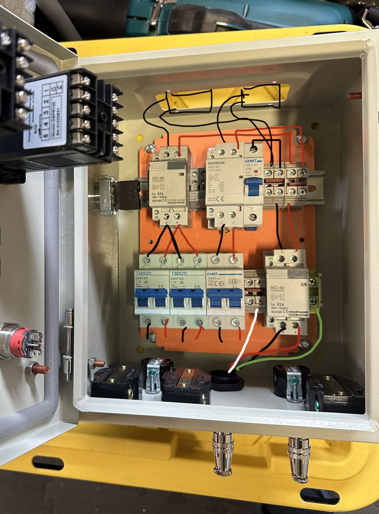
I have most of the controller wired using contactors but can’t wrap my head around the single element switch wiring.

Thanks!
 

Attachments

  • IMG_9021.png
    IMG_9021.png
    425 KB · Views: 0
  • IMG_5013.jpeg
    IMG_5013.jpeg
    1.8 MB · Views: 0
Put some extra contact blocks on your selector switch, and you’ve got it.

Switch position A
Block 1: power to PID A
Block 2: element fire switch to element contactor coil A

Switch position B
Block 1: power to PID B
Block 2: element fire switch to element contactor coil B
 
Why? I can't thing of any reason to do this. PIDs typically use less than 5W of power (2 mA of current @ 240V), why not just leave them both on whenever the system is on?

Brew on :mug:
 
Why? I can't thing of any reason to do this. PIDs typically use less than 5W of power (2 mA of current @ 240V), why not just leave them both on whenever the system is on?

Brew on :mug:
I guess the PIDs can both stay on. I just want the selector switch to manage the single element button and want correct element to fire. I like the cleaner look than having individual element switches.
 
I guess the PIDs can both stay on. I just want the selector switch to manage the single element button and want correct element to fire. I like the cleaner look than having individual element switches.
Then why do you have a 50A panel? Those are usually designed to be able to drive two 5500W elements simultaneously.

I get the attraction of a clean/uncluttered panel, but how do you detect if your system is malfunctioning? When I design panels, there are enough indicators to tell by looking at the panel whether or not things are working as expected.

Brew on :mug:
 
Then why do you have a 50A panel? Those are usually designed to be able to drive two 5500W elements simultaneously.

Brew on :mug:
What I didn’t originally describe is one of the PIDs will be controlling 2 elements in my boil kettle and the other a rims coil element.

One of the contactors splits off to two 30amp breaker and the other a single 30amp breaker.
 
What I didn’t originally describe is one of the PIDs will be controlling 2 elements in my boil kettle and the other a rims coil element.

One of the contactors splits off to two 30amp breaker and the other a single 30amp breaker.
How big is your boil kettle (volume)?

Brew on :mug:
 
Put some extra contact blocks on your selector switch, and you’ve got it.

Switch position A
Block 1: power to PID A
Block 2: element fire switch to element contactor coil A

Switch position B
Block 1: power to PID B
Block 2: element fire switch to element contactor coil B
Thanks! One side should be NO and NC correct?

I might have more questions as I wire those up.
 
Something like this, I believe -

One way using DPDT selector/switch, one way using SPDT selector/switch.

Two SSR One Heater.png
 
Ok so below is a quickly drawn diagram that I hope solves my selector switch with a push button element on switch. Does this look correct? This would be a scenario where both PIDs have constant power but the selector switch selects the element assigned to the PID that it’s switched to.

Is my wiring correct or does the selector switch need to be wired to the ssr power? And not the push button?
 

Attachments

  • IMG_9040.jpeg
    IMG_9040.jpeg
    1 MB · Views: 0
  • IMG_5013.jpeg
    IMG_5013.jpeg
    1.8 MB · Views: 0
The way it's described and then clarified in follow up posts makes this really hard to understand regarding the requirements.

I'll say it another way and you verify if it's right.

You have 50amps coming into the controller. You want one control module to run the boil kettle which has two elements in it. You want the other control module for a RIMS element. You want one switch to select between "boil on" or "rims on" and neither at the same time.

If that's correct, one option:

1x 50 amp contactor
1x 30amp contactor

Source cable runs to the inputs of both of those. You can probably run the 6 gauge wire directly into the set screw lugs and then jump over to the 30a contactor via 10 gauge wire with female push terminals if there's not enough room under the lug also.

On/Off/On low current rotary selector switch with NO contacts on both sides. One "on" position energizes the 50a contactor coil which later splits off to the boil kettle elements. The other "on" position energizes the 30 amp contactor that sends power to the RIMS.


Another option...

Use a single 50amp contactor that is energized via a single "elements enabled" switch and use an on/off/on selector switch simply to interrupt the SSR control signals. There is a very slim chance that a malfunction could power all element outputs at the same time, but that will trip your 50 amp breaker in the main panel if that happened.


Last, not necessarily what you asked...
I've used a single control module (Auber DSPR120) and switched both the element power via the contactor method AND temp probe through stacked blocks on the same switch. There were a lot of questions whether probe circuits could be switched that way but the controller is going strong after a year in use so I guess the answer is yes.
 
Ok so below is a quickly drawn diagram that I hope solves my selector switch with a push button element on switch. Does this look correct? This would be a scenario where both PIDs have constant power but the selector switch selects the element assigned to the PID that it’s switched to.

Is my wiring correct or does the selector switch need to be wired to the ssr power? And not the push button?

Not going to work via that drawing. In order to use a push button, you would need a NC contact going to one contactor coil and a NO contact going to the other contactor coil. That way when it's NOT pressed it might be RIMS ON and when you push it in it would be BOIL ON. You could only have the button illuminate for ONE of those conditions. An On/Off/On selector would be more useful since you gain and off function. Personally I wouldn't leave off an "element firing" light for boil and RIMS... in other words "BOIL FIRING" and "RIMS FIRING"...
 
The way it's described and then clarified in follow up posts makes this really hard to understand regarding the requirements.

Thanks @Bobby_M i was working typing about the same thing.


@handbrewing I think you’ve got this. Just plan it out and make sure you are working within the specs of the components you have (or buy new ones that meet your needs, we’ve all been there).

Draw up your whole diagram and I’m sure some folks here would be happy to take a look and offer advice.
 
I've used a single control module (Auber DSPR120) and switched both the element power via the contactor method AND temp probe through stacked blocks on the same switch.

Not to hijack, but curious. We’re these standard PT100 RTD temp sensors. Did you switch all the conductors?
 
Not going to work via that drawing. In order to use a push button, you would need a NC contact going to one contactor coil and a NO contact going to the other contactor coil. That way when it's NOT pressed it might be RIMS ON and when you push it in it would be BOIL ON. You could only have the button illuminate for ONE of those conditions. An On/Off/On selector would be more useful since you gain and off function. Personally I wouldn't leave off an "element firing" light for boil and RIMS... in other words "BOIL FIRING" and "RIMS FIRING"...
basically mimicking the SSbrewtech V2 econtroller. They have one illuminating push button that fires the element based on the PID that’s selected with the switch.

In my case: 50amp controller, 2 PIDs (boil and rims)

Boil PID selected: boil elements fire when button is pushed and illuminated. Rims stays off.

Rims PID selected: Rims element fires when button is pushed and illuminated. Boil stays off.

Attached is my interior components minus the SSRs. Did a few of the basic wire drawings. Also exterior of box showing pids, selector switch, middle element button and 2 pump buttons. Main power switch is on side of enclosure.

This may have been easier with independent buttons that fire each element but I like the PID selector switch design for whatever reason.
 

Attachments

  • IMG_5013.jpeg
    IMG_5013.jpeg
    1.8 MB · Views: 0
  • IMG_5198.jpeg
    IMG_5198.jpeg
    650.8 KB · Views: 0
The way you describe the SSbrewtech, it's a combination of selector switch AND element enable which is kind of redundant. I would leave both control modules powered up regardless of which function is enabled so you can program them whenever you want.

I'll stand by my first recommendation. 3-position maintained On - Off - On rotary selector switch with two NO contact blocks. Middle position is the same as not pressing any of the pushbuttons on the SSbrewtech.

Two red 240v LEDs... One for Boil firing and one for RIMS firing, both of those are just bridged across the element output receptacles so they fire when the elements do.

I've made a controller just like the one you're describing, but since you can always fire two elements at any given time on 50amps, I actually made it:
2 boil elements enabled.
no boil, 1 RIMS
Added one additional function:
*1 boil element and 1 RIMS element - This was so that the brewer could start up a second batch while the boil was still going. Once you reach a boil, one element running 100% output can take it from there. The RIMS was then used to heat strike water for the next batch.
 
Yeah I realized it’s redundant. I guess the selection and physically pushing a button is satisfying to me. I do plan to keep the PIDs maintained with power so they can be adjusted.
 
Ok Gents,

I have my controller all wired up. I did a test last night and I seem to have an issue with the elements not turning off when the PID isn't sending a signal.

The elements are off when the push button is off which is correct.
The button is pushed the selected contactor switches on and the receptacle receives power which is correct.

However the receptacle power doesnt seem to be affected by the PID control output.

The lights on the SSR seem to function properly by turning off and on whether above or below the set temp. However the receptacle don't turn off when suppose to.

The element receptacles are on when the SSR light is on and also seem to be on when the SSR light turns off (when the set temp is below the probe temp). I was simply testing if the 30A receptacle had power with a non-contact voltage detector. I haven't tested with the actual elements hooked up.

It's the same experience with both SSRs, whether I have PID 1 or 2 selected the assigned receptacle stays on.

One of the SSRs is new and other was out of my old controller but still worked.

Here is the wiring diagram of the elements.

What am I missing here?

FGyugKE.jpg
 
The element receptacles are on when the SSR light is on and also seem to be on when the SSR light turns off (when the set temp is below the probe temp). I was simply testing if the 30A receptacle had power with a non-contact voltage detector. I haven't tested with the actual elements hooked up.
Try with a load hooked up (element etc,,) SSR's will leak current across the circuit without a load attached and provide an "ON" situation.
 
Back
Top