Just wondering if anyone has any ideas on what my problem could be. Recently I bought a used 1bbl Colorado brewing system (didn't do my research before to find out they are out of business). Hooked everything up and it doesn't heat the elements. I have tested the power all the way down to where the plug and the element are connected and am getting power. I thought maybe the elements had been broken or fired up without water so I bought a couple new ones and still no heat. Any ideas with what could be wrong? Any help would be appreciated!
You are using an out of date browser. It may not display this or other websites correctly.
You should upgrade or use an alternative browser.
You should upgrade or use an alternative browser.
Two 5500 watt 240v heating elements not heating up.
- Thread starter LoganBrew
- Start date

Help Support Homebrew Talk:
This site may earn a commission from merchant affiliate
links, including eBay, Amazon, and others.
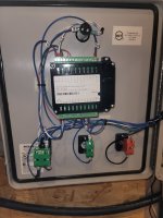
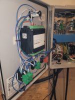
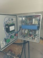
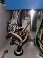
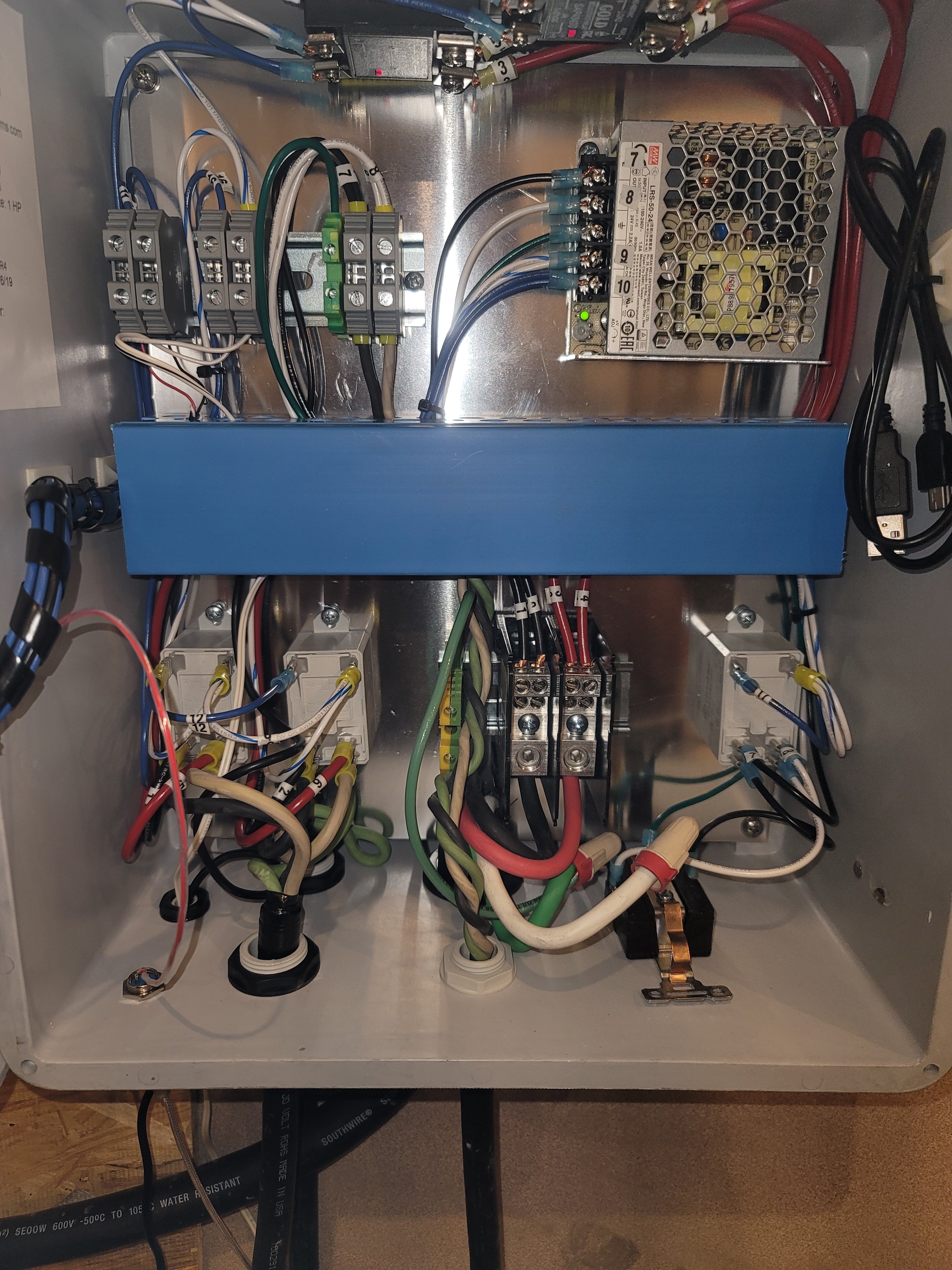
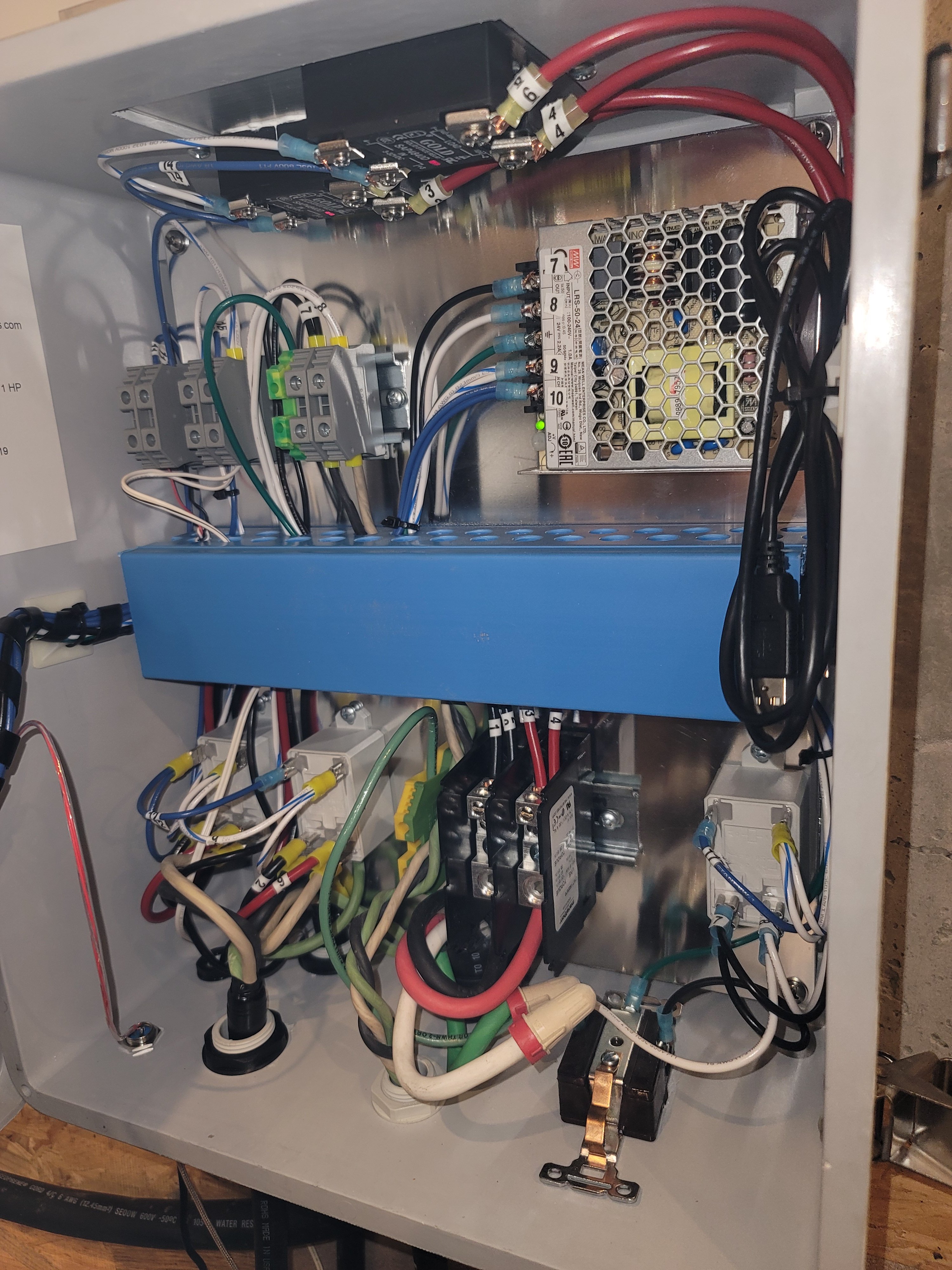
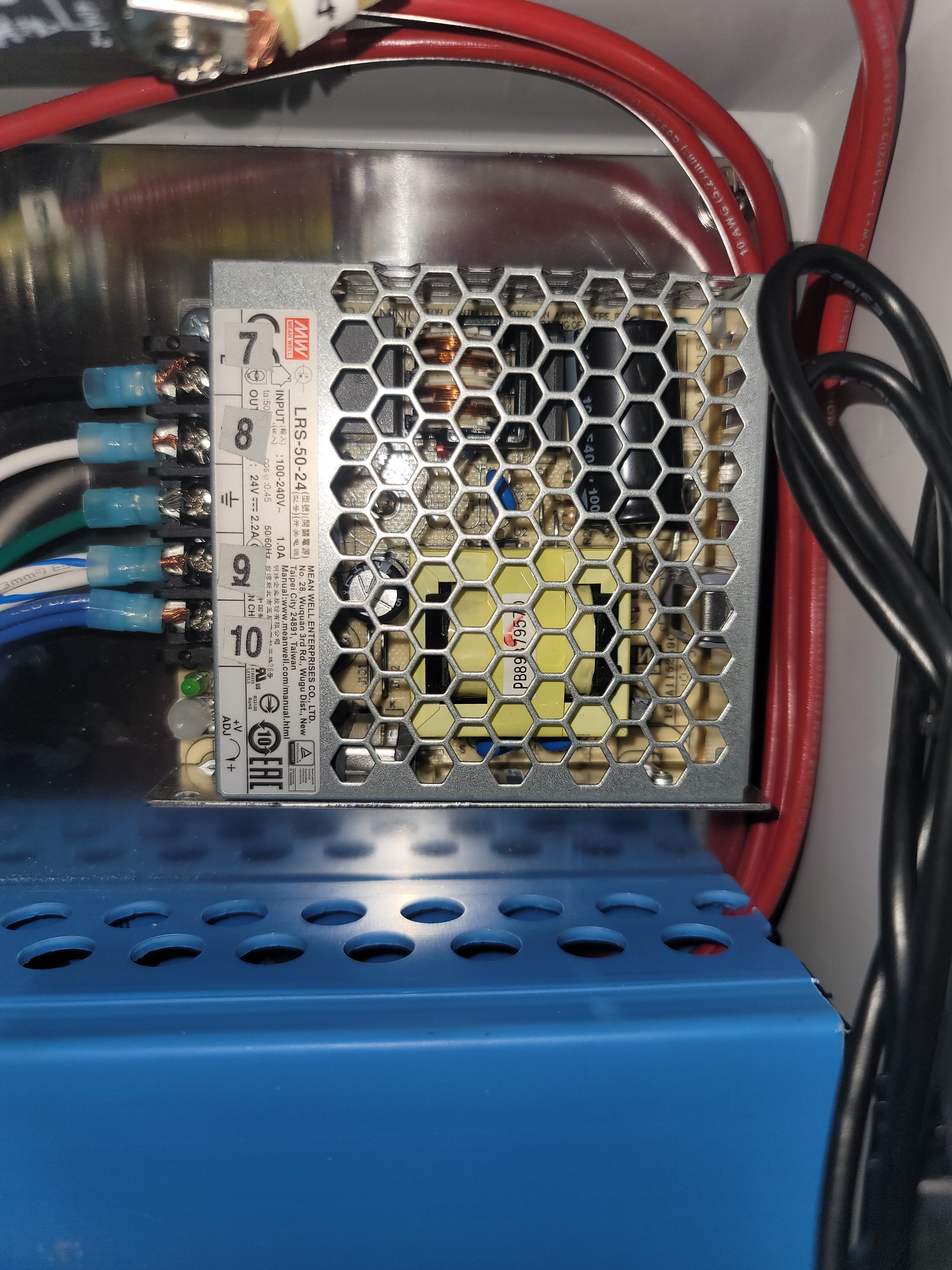
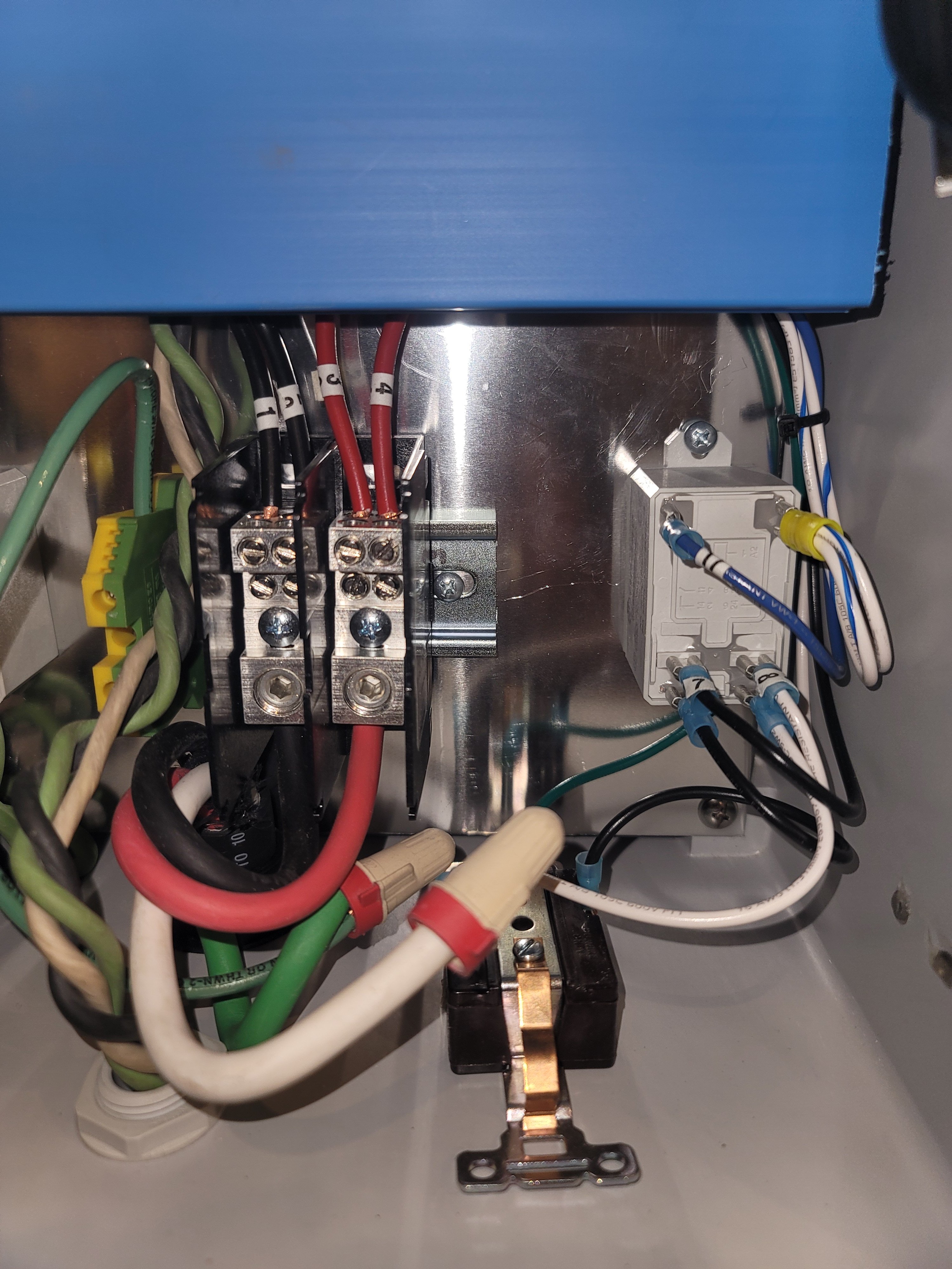
Is there a schematic available for the control panel? If not, can you post a bunch of high resolution, well focused, pics of the insides of the control panel enclosure. The more angles the better.
Brew on
Brew on
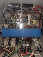
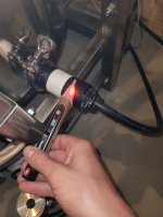
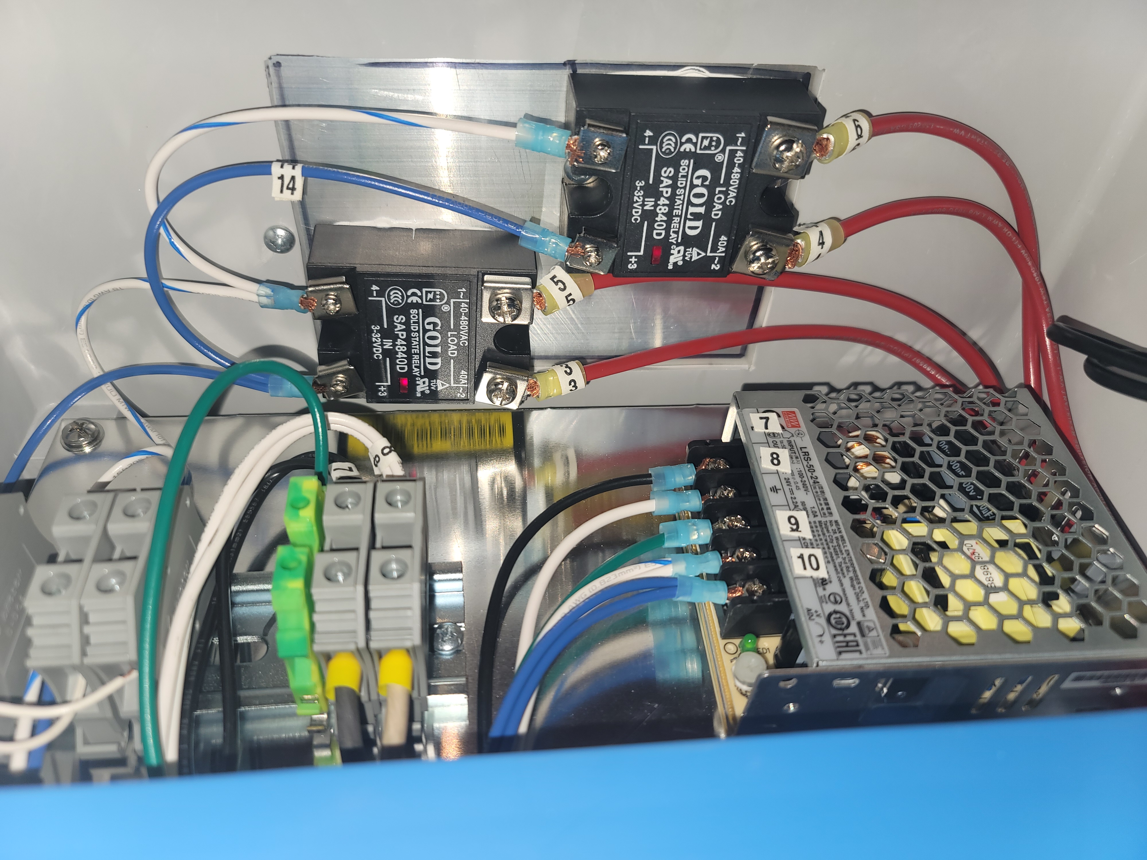
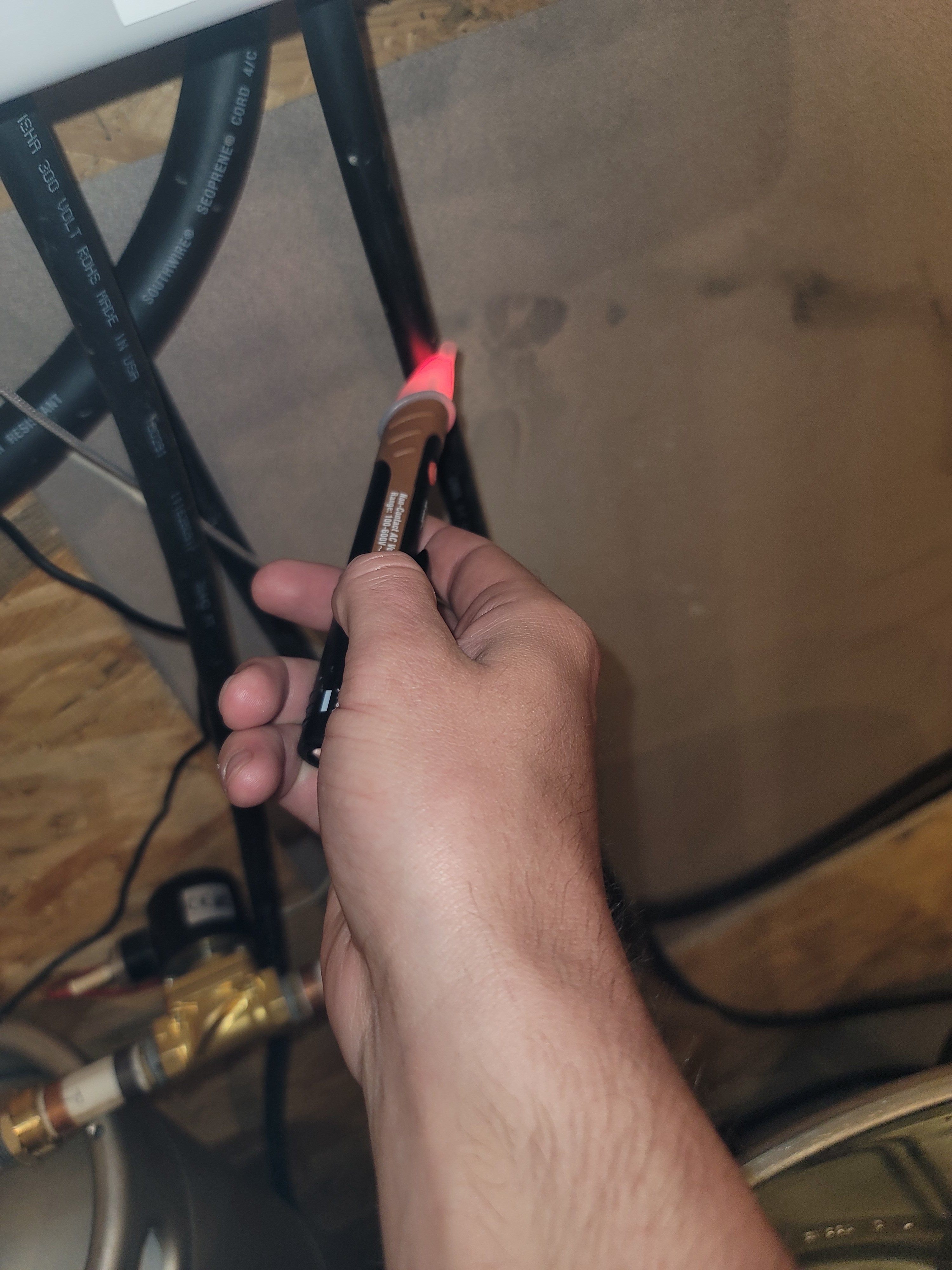
The tricky part is that SSRs will pass voltage even if they are not getting a signal to "fire". You can look inside at the SSRs and see if they are getting the control signal as the red LED on the relay itself will be on or flashing. If it's dark, the control signal is not hitting it.
Hope these help
Attachments
-
 20210513_212122.jpg1.3 MB
 -
 20210513_212138.jpg1.4 MB
 -
 20210513_212142.jpg1.3 MB
 -
 20210513_212149.jpg1.5 MB
 -
 20210513_212159.jpg1.8 MB
 -
 20210513_212207.jpg1.8 MB
 -
 20210513_212212.jpg1.6 MB
 -
 20210513_212217.jpg2 MB
 -
 20210513_212225.jpg3 MB
 -
 20210513_212229.jpg2 MB
 -
 20210513_212229.jpg2 MB
 -
 20210513_212233.jpg1.8 MB
 -
 20210513_212240.jpg1.5 MB
 -
 20210513_212243.jpg1.4 MB
 -
 20210513_212243.jpg1.4 MB
 -
 20210513_212331.jpg1.2 MB
 -
 20210513_212335.jpg1.3 MB
 -
 20210513_212343.jpg1.4 MB
 -
 20210513_212356.jpg1.3 MB
 -
 20210513_212358.jpg1.3 MB
 -
 20210513_212401.jpg1.2 MB
 -
 20210513_212405.jpg1.3 MB


RufusBrewer
Well-Known Member
Putting a meter across two terminals can be misleading. You can read 240 VAC, but the signal might not be able to provide the current to do the work.
The best thing to do is put the meter probes on the terminals while a heating element is connected. Known as testing/measuring under load conditions. You may or may not be able to do this in a safe manor. Depends on the mechanical design of your rig.
Other things to look for is that somebody confused an SSR (Solid State Relay) with an SSVR (Solid State Voltage Regulator).
You can take a 9 volt battery and apply it to input terminals of the SSR as an alternative to using the PID. Disconnect the PID first and know that you could be running the heating element @ 100%.
Good luck.


$56.70
Wilbur Curtis Thermal Dispenser Seamless Pourpot, 64 Oz, Ss Exterior/Liner, Brew-Thru Lid - Commercial Airpot Pourpot Beverage Dispenser - CLXP6401S100 (Each)
BEACON HILL ( ALL Serial NUMBERS recorded)


$172.35
2 Inch Tri Clamp Keg Manifold With Ball Lock Posts, Pressure Gauge, PRV (0-30 PSI) – Homebrew, Fermentation, Kegging System
wuhanshijiayangzhiyimaoyiyouxiangongsi


$58.16
HUIZHUGS Brewing Equipment Keg Ball Lock Faucet 30cm Reinforced Silicone Hose Secondary Fermentation Homebrew Kegging Brewing Equipment
xiangshuizhenzhanglingfengshop


$22.00 ($623.23 / Ounce)
AMZLMPKNTW Ball Lock Sample Faucet 30cm Reinforced Silicone Hose Secondary Fermentation Homebrew Kegging joyful
无为中南商贸有限公司


$7.79 ($7.79 / Count)
Craft A Brew - LalBrew Voss™ - Kveik Ale Yeast - For Craft Lagers - Ingredients for Home Brewing - Beer Making Supplies - (1 Pack)
Craft a Brew

$53.24
1pc Hose Barb/MFL 1.5" Tri Clamp to Ball Lock Post Liquid Gas Homebrew Kegging Fermentation Parts Brewer Hardware SUS304(Gas MFL)
Guangshui Weilu You Trading Co., Ltd


$33.99 ($17.00 / Count)
$41.99 ($21.00 / Count)
2 Pack 1 Gallon Large Fermentation Jars with 3 Airlocks and 2 SCREW Lids(100% Airtight Heavy Duty Lid w Silicone) - Wide Mouth Glass Jars w Scale Mark - Pickle Jars for Sauerkraut, Sourdough Starter
Qianfenie Direct


$20.94
$29.99
The Brew Your Own Big Book of Clone Recipes: Featuring 300 Homebrew Recipes from Your Favorite Breweries
Amazon.com

$53.24
1pc Hose Barb/MFL 1.5" Tri Clamp to Ball Lock Post Liquid Gas Homebrew Kegging Fermentation Parts Brewer Hardware SUS304(Liquid Hose Barb)
yunchengshiyanhuqucuichendianzishangwuyouxiangongsi


$10.99 ($31.16 / Ounce)
Hornindal Kveik Yeast for Homebrewing - Mead, Cider, Wine, Beer - 10g Packet - Saccharomyces Cerevisiae - Sold by Shadowhive.com
Shadowhive


$176.97
1pc Commercial Keg Manifold 2" Tri Clamp,Ball Lock Tapping Head,Pressure Gauge/Adjustable PRV for Kegging,Fermentation Control
hanhanbaihuoxiaoshoudian


![Craft A Brew - Safale S-04 Dry Yeast - Fermentis - English Ale Dry Yeast - For English and American Ales and Hard Apple Ciders - Ingredients for Home Brewing - Beer Making Supplies - [1 Pack]](https://m.media-amazon.com/images/I/41fVGNh6JfL._SL500_.jpg)
$6.95 ($17.38 / Ounce)
$7.47 ($18.68 / Ounce)
Craft A Brew - Safale S-04 Dry Yeast - Fermentis - English Ale Dry Yeast - For English and American Ales and Hard Apple Ciders - Ingredients for Home Brewing - Beer Making Supplies - [1 Pack]
Hobby Homebrew


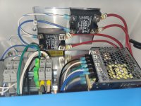
The SSRs are legit, based on the photos....
Other things to look for is that somebody confused an SSR (Solid State Relay) with an SSVR (Solid State Voltage Regulator).
...
Brew on
I don't really know a lot about electrical stuff but we have the two elements and they are 240v 5500w and have it hooked up to a 40 amp breaker. In my head I would think that the elements would be heating up a little bit or blow the breaker if it was trying to pull to much power. But not since it's not doing anything I'm stumped.
Toxxyc
New and loving it
5,500W 240V will be fine on a 40A breaker. Have you tried wiring up the elements to a simple extension (make sure it's thick enough) and plugging it into the breaker directly, without the control box in the middle?
Mad Mann
Well-Known Member
- Joined
- Nov 15, 2020
- Messages
- 65
- Reaction score
- 45
Sounds like you are going to have to do some good old trouble shooting. Suggest starting with simple things first. Unplug your controller and check that you have continuity on all wires starting with the load side of the SSR. SSRs, if failed, can fail open or closed; if this is the case it will show it is firing but either stay on all the time or not allow any current to pass. I have also seen PIDs that fail that contribute to electrical issues. A thread above mentioned a way to test the SSRs. Kal has schematics available but for the system he designed.
5,500W 240V will be fine on a 40A breaker. Have you tried wiring up the elements to a simple extension (make sure it's thick enough) and plugging it into the breaker directly, without the control box in the middle?
He wrote "TWO" 5500 watt elements and that requires 50 amps, not 40. When it's working, it will trip the breaker..
Toxxyc
New and loving it
Yup but I said one. He can plug one directly into a breaker and see where the problem lies. If it works, elements are fine. If it doesn't problem is somewhere in the control box.He wrote "TWO" 5500 watt elements and that requires 50 amps, not 40. When it's working, it will trip the breaker..
Also, an inline coil ammeter will also work well on the feedline to one or both of the elements, you'll be able to see what current goes to the elements and see where the issue lies.
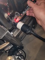
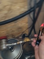
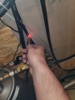
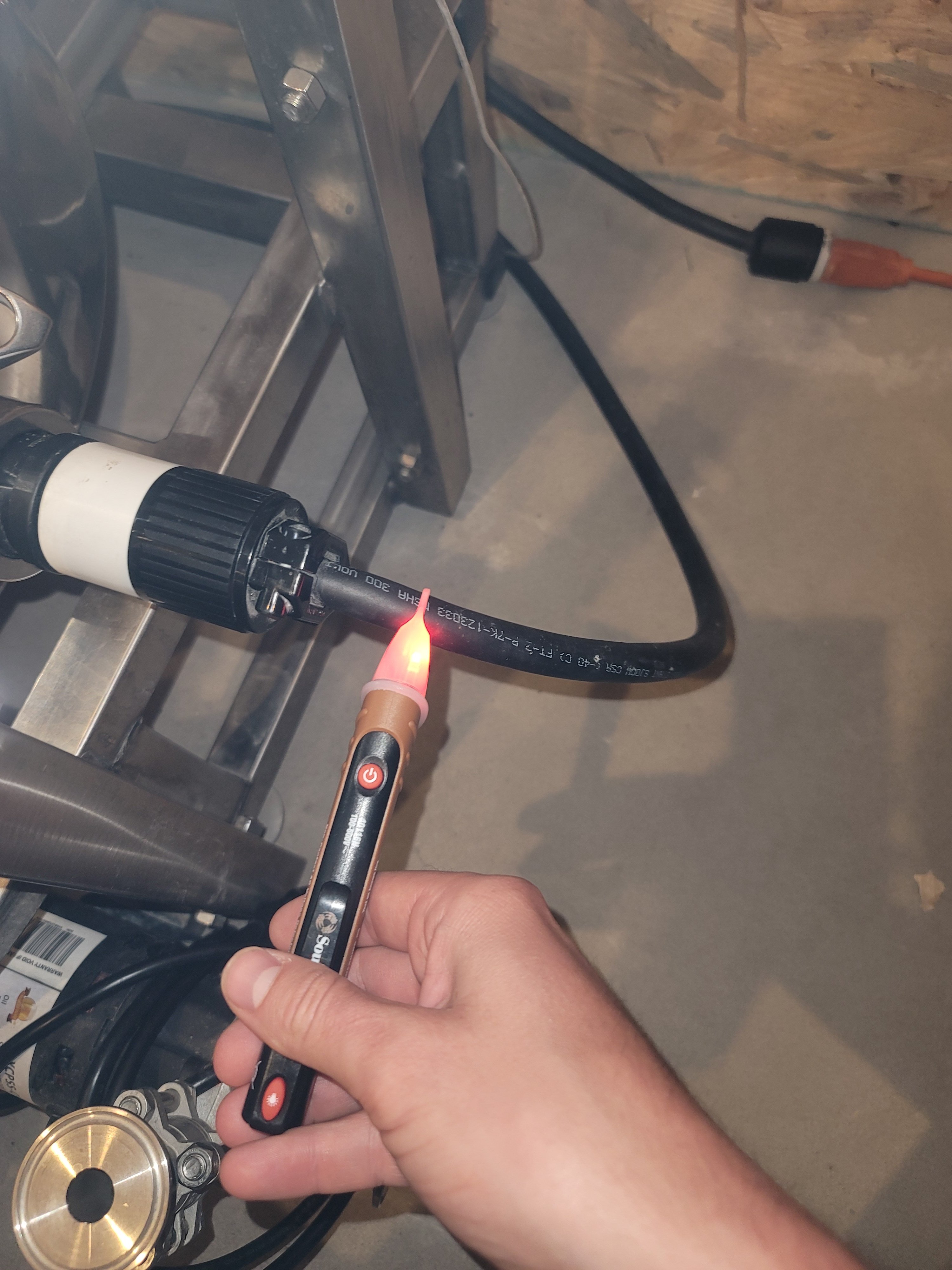
What is the lighted test probe you are using? Specifically, what is it testing for? Also, the pictures you provided are very good - much better than a lot of others that ask for help often provide.
I think I have figured out the basic design of this controller.
There are two SSRs - do the LEDs on both of them flash (you said at least one flashed)? The LED flashing indicates that the SSR is receiving a signal to turn on. If the SSRs are receiving a modulated control signal, that indicates that the PLC output to the SSRs is working. You will have voltage at the elements whether the SSRs are working or not. If the SSRs are not working, then you will have no current or power at the elements (even if you have voltage.)
If the element contactors (mechanical relays) are malfunctioning such that none of the contacts close, then there will be no voltage at the elements. If some, but not all, of the contacts close, then you will have voltage at the elements, but no current or power.
That's what I have so far.
Brew on
I think I have figured out the basic design of this controller.
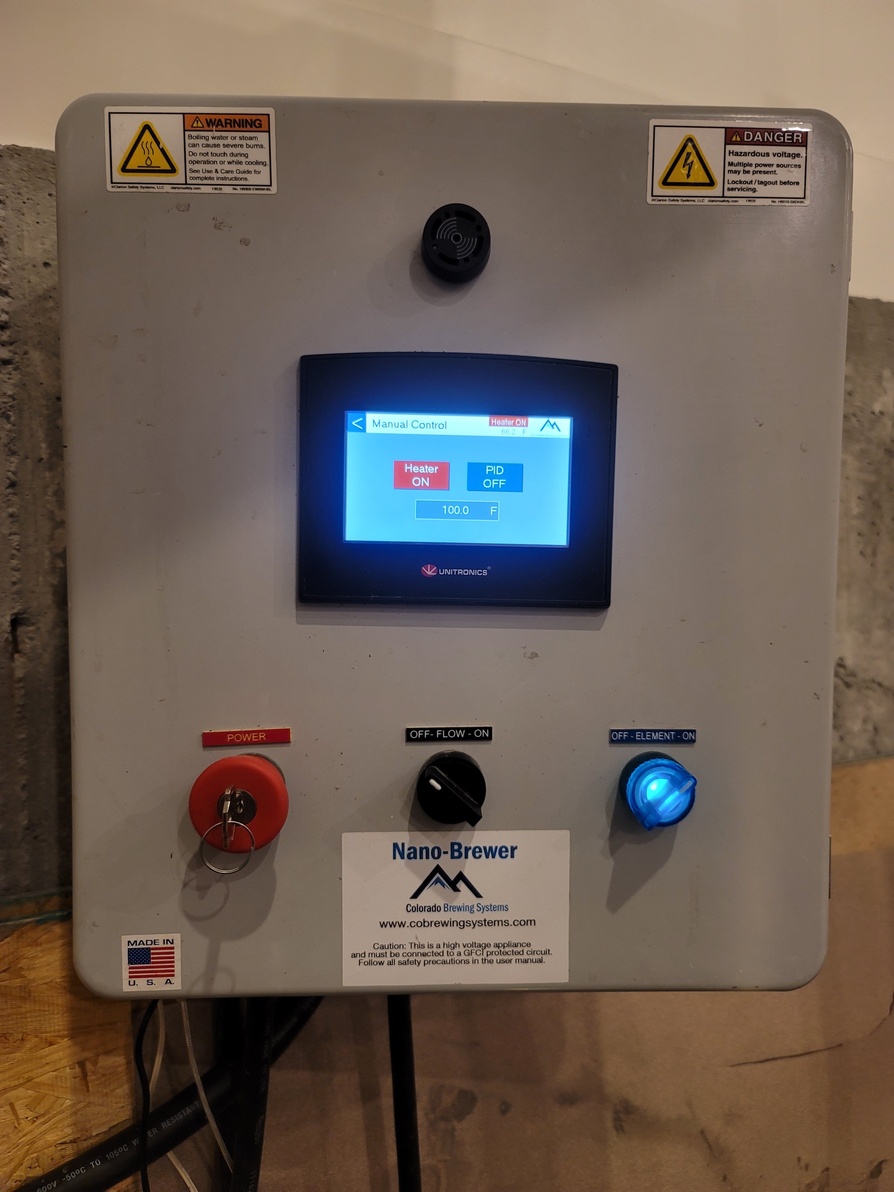
- The "brains" are a Unitronics PLC+HMI (Programable Logic Controller + Human Machine Interface [the touch screen LCD.] The PLC provides the PID function for the system (and probably other things as well.)
- It is a single vessel controller that controls two elements which always fire simultaneously. Since each element draws 5500/240 = 22.9A, the box needs to be feed from a minimum 50A circuit, and 60A would be better.
- It also controls a single pump thru a mechanical relay controlled by the PLC, with a mechanical enable switch between the PLC and the pump relay.
- One of the hot lines goes from the input power thru two element relays and then to the two elements.
- The other hot line goes from the input power to two SSRs, then to the two element relays, and then to the two elements.
- A single (lighted) mechanical switch controls both element relays simultaneously. This provides galvanic isolation of the input power from the elements when this switch is off. This switch lights up when the switch is on.
- The PLC drives both SSRs with a single control input, so both SSRs are on and off at the same time.
There are two SSRs - do the LEDs on both of them flash (you said at least one flashed)? The LED flashing indicates that the SSR is receiving a signal to turn on. If the SSRs are receiving a modulated control signal, that indicates that the PLC output to the SSRs is working. You will have voltage at the elements whether the SSRs are working or not. If the SSRs are not working, then you will have no current or power at the elements (even if you have voltage.)
If the element contactors (mechanical relays) are malfunctioning such that none of the contacts close, then there will be no voltage at the elements. If some, but not all, of the contacts close, then you will have voltage at the elements, but no current or power.
That's what I have so far.
Brew on
Last edited:
How are your elements connected to the control panel? Do you have the TC base elements with integral L6-30 plug, or are the element cords hard wired (screwed) to the element terminals?
You can do a lot better with diagnosing problems if you get a digital volt/ohm meter, than with the probe you are using.
Brew on
You can do a lot better with diagnosing problems if you get a digital volt/ohm meter, than with the probe you are using.
Brew on
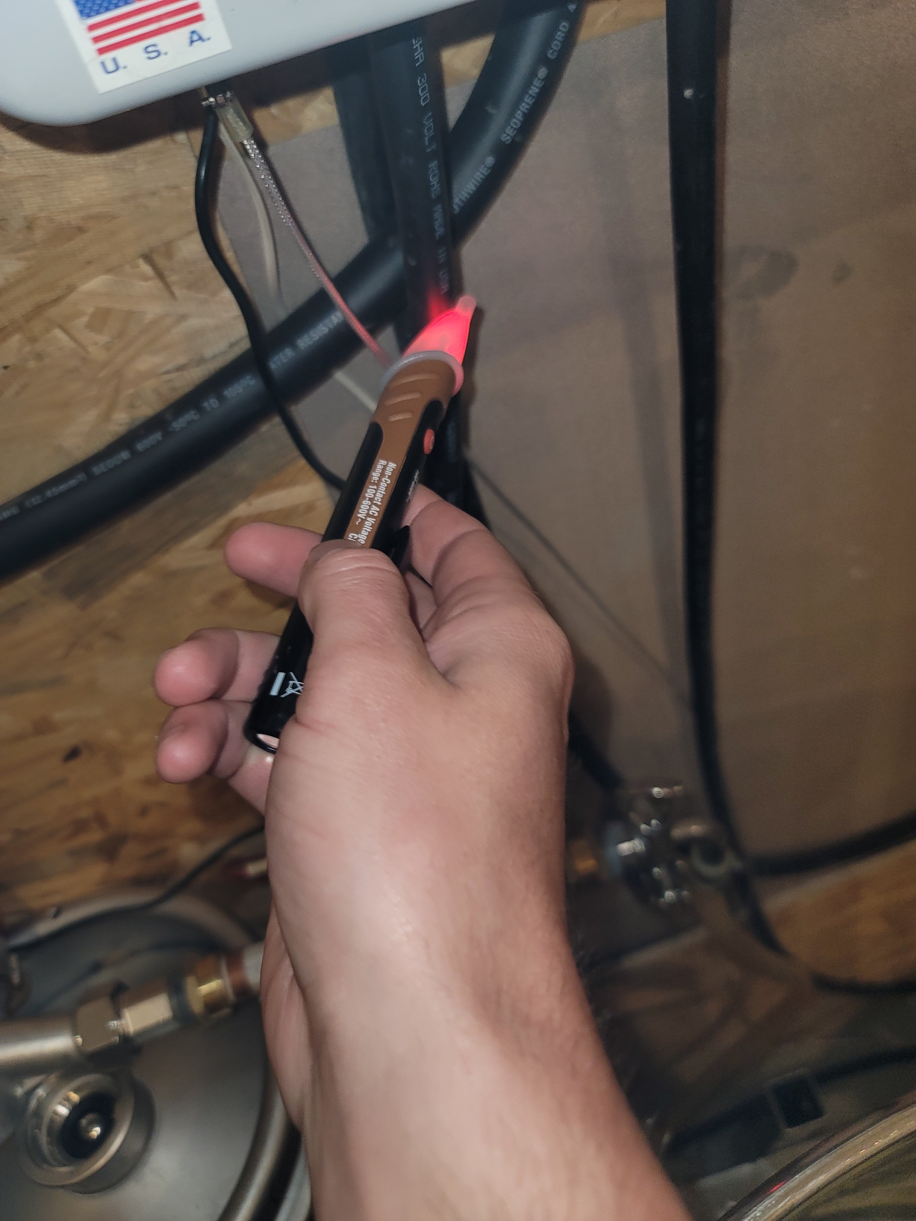
That tester is just an induction based voltage detector which you'd use to quickly tell you if the circuit you're about to work on is indeed as off as you think it is. An SSR would pass enough current to light it up.
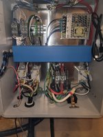
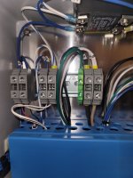
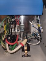
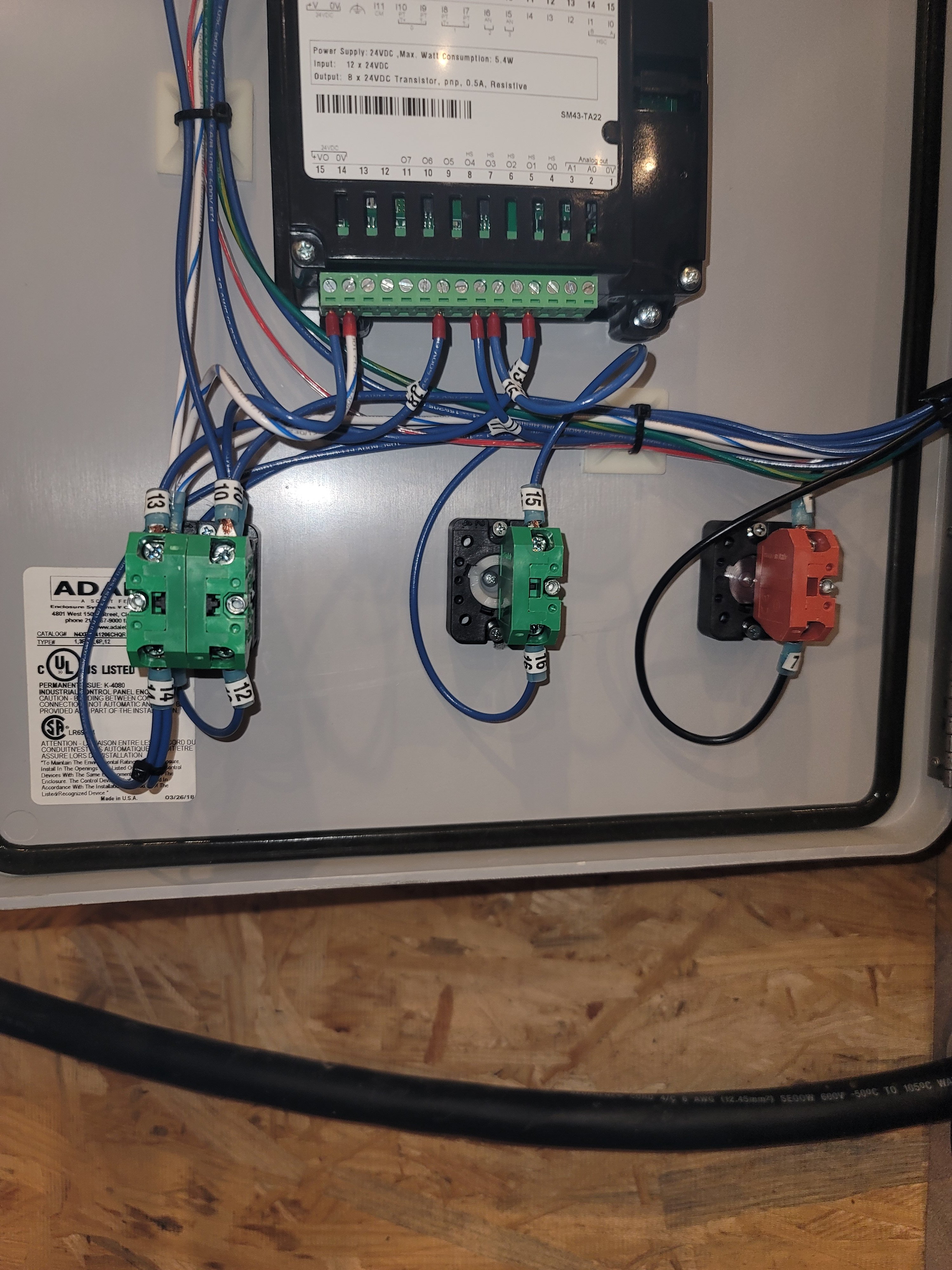
Can you get a closeup of the specs on those mechanical relays? It's the pair of off white rectangular units next to each other. It looks like the incoming neutral "white" wire may be just wirenutted off. I'm wondering if those relay coils might be 120v and in that case, the disconnected neutral would explain why it's not closing those relays.
The neutral on the 240V feed cable is indeed dead ended at a wire nut. However, I'm assuming the relays have 24V DC coils. The white wires with blue stripe seem to all be connected back to the negative output of the 24V DC power supply.Can you get a closeup of the specs on those mechanical relays? It's the pair of off white rectangular units next to each other. It looks like the incoming neutral "white" wire may be just wirenutted off. I'm wondering if those relay coils might be 120v and in that case, the disconnected neutral would explain why it's not closing those relays.
The panel also appears to have a separate 120V power feed, which is used for the pump, and maybe the 24V power supply.
Brew on
@LoganBrew There is a white two wire zip cord with black line that exits the bottom of the control panel. Where does this go? It appears to have something to do with the pump control.
Also, did you receive any operating instructions with the unit? Are they in pdf format (or can you create a pdf from them) that you can upload?
Brew on
Also, did you receive any operating instructions with the unit? Are they in pdf format (or can you create a pdf from them) that you can upload?
Brew on
Last edited:
ITV
Well-Known Member
I suggest starting with the basics since it never worked. I would measure the voltage at the power distribution block (Red & Black wires). You should read 240VAC, if not then check the power feed from your breaker panel.
faithie999
Well-Known Member
- Joined
- Jun 27, 2008
- Messages
- 144
- Reaction score
- 88
do you have the manual/wiring diagram?
Ok, here is what I have reverse engineered about the high current control circuits. The failure must be somewhere in this section of circuitry, or the elements are bad or connected incorrectly.

That's it for tonight.
Brew on
That's it for tonight.
Brew on
bruce_the_loon
Well-Known Member
Looking at the 2nd photo, that upper connector bank seems to be partially unplugged from the PID controller. See if you can push it deeper into the sockets, just push downwards. It might just be that the socket bank below it is mounted skew, but it might also be unplugged on the one side.
- Joined
- Jul 12, 2017
- Messages
- 489
- Reaction score
- 422
Good eye bruce_the_loon.
The end that appears to be least well plugged in contains the power feed to the PLC and the Pt100 temp probe. If this connector were the problem, the PLC display would not even light up.Looking at the 2nd photo, that upper connector bank seems to be partially unplugged from the PID controller. See if you can push it deeper into the sockets, just push downwards. It might just be that the socket bank below it is mounted skew, but it might also be unplugged on the one side.
Brew on
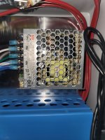
If you get a proper multi-meter, the next step would be to measure the two coil terminals on the relays to see if they are getting 24 VDC.
The relays/contactors you want to check are outlined in yellow below. The one on the right side is for the pump. Coil terminals are on the top. The blue wires are positive and the white with blue stripe are negative. In the schematic a few posts above, the blue wires are represented by blue lines and the white with blue stripe represented by cyan lines.If you get a proper multi-meter, the next step would be to measure the two coil terminals on the relays to see if they are getting 24 VDC.
To check the voltage at the relay coils, power up the system and turn the element switch on. Set the multimeter to read DC volts, and place the red probe on the positive (left) coil terminal, and the black probe on the negative (right) terminal. If you reverse the probe you should read -24V rather than +24V.

Brew on
Last edited:
the white two wire zip cord goes to the solenoid for the water pump@LoganBrew There is a white two wire zip cord with black line that exits the bottom of the control panel. Where does this go? It appears to have something to do with the pump control.
Also, did you receive any operating instructions with the unit? Are they in pdf format (or can you create a pdf from them) that you can upload?
Brew on
Similar threads
- Replies
- 20
- Views
- 1K
- Replies
- 9
- Views
- 779
- Replies
- 25
- Views
- 2K
- Replies
- 6
- Views
- 1K
