Awesome! I've not yet had the pleasure, but next time I'm in Sac, I'll look for some bottles. What do you recommend?
You are using an out of date browser. It may not display this or other websites correctly.
You should upgrade or use an alternative browser.
You should upgrade or use an alternative browser.
Show us your sculpture or brew rig
- Thread starter Onescalerguy
- Start date

Help Support Homebrew Talk:
This site may earn a commission from merchant affiliate
links, including eBay, Amazon, and others.
I just drew up some plans for a simple 2-tier wooden stand. I'll be buying materials and building it tomorrow, then I'll post the pictures of it here when I'm done.
Demon
Well-Known Member
Not my homebrew setup, but I like shiny stuff so I'll post it anyway. This is the 3.5bbl PsychoBrew system for my brewery in Chicago, we'll be open in September. The system is customized from their typical 4 burner system by using larger mash tuns and stainless steel pumps.

Most homebrew setups are HLT, MT, BK. I'm curious to know the purpose of the 4th kettle. Full of PBW to clean house afterward?
Demon
Well-Known Member
Most homebrew setups are HLT, MT, BK. I'm curious to know the purpose of the 4th kettle. Full of PBW to clean house afterward?
Two 75gal mash tuns in the center, two 75gal boil kettles on the ends. No hot liquor tank, we use a large tankless water heater that puts out 185* water on demand.


$58.16
HUIZHUGS Brewing Equipment Keg Ball Lock Faucet 30cm Reinforced Silicone Hose Secondary Fermentation Homebrew Kegging Brewing Equipment
xiangshuizhenzhanglingfengshop

$10.99 ($31.16 / Ounce)
Hornindal Kveik Yeast for Homebrewing - Mead, Cider, Wine, Beer - 10g Packet - Saccharomyces Cerevisiae - Sold by Shadowhive.com
Shadowhive


$20.94
$29.99
The Brew Your Own Big Book of Clone Recipes: Featuring 300 Homebrew Recipes from Your Favorite Breweries
Amazon.com


$53.24
1pc Hose Barb/MFL 1.5" Tri Clamp to Ball Lock Post Liquid Gas Homebrew Kegging Fermentation Parts Brewer Hardware SUS304(Liquid Hose Barb)
Guangshui Weilu You Trading Co., Ltd

![Craft A Brew - Safale BE-256 Yeast - Fermentis - Belgian Ale Dry Yeast - For Belgian & Strong Ales - Ingredients for Home Brewing - Beer Making Supplies - [3 Pack]](https://m.media-amazon.com/images/I/51bcKEwQmWL._SL500_.jpg)


$7.79 ($7.79 / Count)
Craft A Brew - LalBrew Voss™ - Kveik Ale Yeast - For Craft Lagers - Ingredients for Home Brewing - Beer Making Supplies - (1 Pack)
Craft a Brew


$22.00 ($623.23 / Ounce)
AMZLMPKNTW Ball Lock Sample Faucet 30cm Reinforced Silicone Hose Secondary Fermentation Homebrew Kegging joyful
无为中南商贸有限公司


$176.97
1pc Commercial Keg Manifold 2" Tri Clamp,Ball Lock Tapping Head,Pressure Gauge/Adjustable PRV for Kegging,Fermentation Control
hanhanbaihuoxiaoshoudian


$53.24
1pc Hose Barb/MFL 1.5" Tri Clamp to Ball Lock Post Liquid Gas Homebrew Kegging Fermentation Parts Brewer Hardware SUS304(Liquid MFL)
yunchengshiyanhuqucuichendianzishangwuyouxiangongsi


$33.99 ($17.00 / Count)
$41.99 ($21.00 / Count)
2 Pack 1 Gallon Large Fermentation Jars with 3 Airlocks and 2 SCREW Lids(100% Airtight Heavy Duty Lid w Silicone) - Wide Mouth Glass Jars w Scale Mark - Pickle Jars for Sauerkraut, Sourdough Starter
Qianfenie Direct


$172.35
2 Inch Tri Clamp Keg Manifold With Ball Lock Posts, Pressure Gauge, PRV (0-30 PSI) – Homebrew, Fermentation, Kegging System
wuhanshijiayangzhiyimaoyiyouxiangongsi


Gotcha. Do you blend the wort into a single fermentor, or are they typically used for different batches?
Demon
Well-Known Member
Blended in to the same fermenter. In an 8-10 hour brew day we can fill a 7bbl fermenter.
trub quaffer
Well-Known Member

Just finished mine last week. More pics posted in the automated brewing forum.
Just put the finishing touches on my two tier stand for three tier brewing. Can't wait to brew with it, it should make life a whole lot easier. Built out of 2x4's and 3/4" plywood, put on casters. Real easy to move around and should put everything at hand rather than running around everywhere on brew day. Got room for the propane tank, CFC, filter, and spare hoses. Dimensions are 2' by 6' for the bottom tier, top tier is 2' by 3.5'. To the top shelf is 39".

dyqik
Well-Known Member
I used this system for the first time yesterday. CampChef burner, two 5 gallon coolers, an 8 gallon kettle from Morebeer and a CFC bought from another forum user and some commercial shelving from Costco ($30).
I have a eBay tan pump on the way so I don't have to lift the full HLT or full kettle for cooling next time.
Fly-sparging under gravity

Feeding the CFC under gravity

I have a eBay tan pump on the way so I don't have to lift the full HLT or full kettle for cooling next time.
Fly-sparging under gravity

Feeding the CFC under gravity

Travestian
Well-Known Member
What container is your CFC flowing into? The bucket? What kind of temperature are you seeing out the end of the CFC after only the one pass?
StinkyVp
Dictator
Just put the finishing touches on my two tier stand for three tier brewing. Can't wait to brew with it, it should make life a whole lot easier. Built out of 2x4's and 3/4" plywood, put on casters. Real easy to move around and should put everything at hand rather than running around everywhere on brew day. Got room for the propane tank, CFC, filter, and spare hoses. Dimensions are 2' by 6' for the bottom tier, top tier is 2' by 3.5'. To the top shelf is 39".
That is the coolest thing I've ever seen. Can you get a closer photo of how the legs attach to the lower level? I'm going to build something like this. I think I may have something close already using an old desk and adding casters.

NWAleDad said:I have waited a long time to post to this thread. In the words of Sean Connery THE DAY IS MINE! Finished her on Sunday and going to run through the first brew this coming saturday.
Awesome job! I wish I could be that automated!
dyqik
Well-Known Member
What container is your CFC flowing into? The bucket? What kind of temperature are you seeing out the end of the CFC after only the one pass?
This was my first go using the cfc, and I got 78 in the bucket from near boiling in the kettle. Since it was 95 outside, this wasn't too disappointing, although I'm sure I used a lot of cooling water. A couple of hours in the fermentation cabinet got it down to pitching temps. Since I'll have a pump next time I brew, recirculation should be easy, which will also get the cold break out.
That is the coolest thing I've ever seen. Can you get a closer photo of how the legs attach to the lower level? I'm going to build something like this. I think I may have something close already using an old desk and adding casters.
Here's a close up of the underside of where one of the legs attaches to the upper level frame. The bottom is attached the same way, I have a 2x4 running in the middle of the bottom level under the plywood that can't be seen. The two center legs are anchored to this piece. Everything is just screwed together with a box of deck screws I had laying around.

NWAleDad said:I have waited a long time to post to this thread. In the words of Sean Connery THE DAY IS MINE! Finished her on Sunday and going to run through the first brew this coming saturday.
Can I ask what you are using for your MLT burner (in the middle I assume?). I can see you have 10" banjos for the HLT and bk. I am building a Brutus 10 as well and have one 10" banjo now (from my kab4) and thought I would get a second one for the HLT and bk and use a 6" banjo for the MLT. Trying to figure out the regulator setup for that mix.
Can I ask what you are using for your MLT burner (in the middle I assume?). I can see you have 10" banjos for the HLT and bk. I am building a Brutus 10 as well and have one 10" banjo now (from my kab4) and thought I would get a second one for the HLT and bk and use a 6" banjo for the MLT. Trying to figure out the regulator setup for that mix.
my MLT is not direct fire. No burner for the MLT, only the HLT and BK.
NWAleDad said:my MLT is not direct fire. No burner for the MLT, only the HLT and BK.
Ah that explains it thanks. I would like to fire my mash tun for steps and mashouts but definitely don't need a 10" banjo just something small. But I need I figure out what regulator for both.
Ah that explains it thanks. I would like to fire my mash tun for steps and mashouts but definitely don't need a 10" banjo just something small. But I need I figure out what regulator for both.
You can just do step infusion mashes, they are much more gentle than direct fire. With direct fire mash you are going to need some good mixing to avoid scorching your mash. That the way I did it till i built my herms system.
You can just do step infusion mashes, they are much more gentle than direct fire. With direct fire mash you are going to need some good mixing to avoid scorching your mash. That the way I did it till i built my herms system.
Yep, that is why I did not add burner for the MLT. I can easily run the wort through my HEX at the desired temp. in a scenario like this (and for the first few uses) i'm going to measure the temp between the MLT and exit of the HEX and compensate for heat loss.
I haven't tried step infusions but it seems easier to direct fire while recirculating with a pump, like Lonnie Mac does on his original Brutus 10. I figure moving up to a HERMS is the next step, seems like that would get the most accurate temps but it sounds like people are successful direct firing as long as a recirc is running?
groundchuck
Well-Known Member
I tried to go with a stand that was as small / simple as I could get. I checked out lots of other designs to figure out how to make this one. It's pretty simple to make.
1 - 4x8 (3/8") sheet of particle board
7 - 2"x4"x8' boards
Box of 2 3/4" screws
Casters of your choice
I used it once already to make an American Wheat. We are planning for the next brew shortly.

1 - 4x8 (3/8") sheet of particle board
7 - 2"x4"x8' boards
Box of 2 3/4" screws
Casters of your choice
I used it once already to make an American Wheat. We are planning for the next brew shortly.
I haven't tried step infusions but it seems easier to direct fire while recirculating with a pump, like Lonnie Mac does on his original Brutus 10. I figure moving up to a HERMS is the next step, seems like that would get the most accurate temps but it sounds like people are successful direct firing as long as a recirc is running?
As long as you have good flow and accurate control over mash temp, direct fire works very well.
Smithy
Well-Known Member
Curious as to why so many benches are referred to as "Brutus" design? The design of such a bench and the arrangement of the kettles lend itself to "form follows function" and common sense design when using pumps for transfer. It also allows for stability, user interaction, and clean storage.
Prior to my bench design and build I didn't know what a "Brutus 10". I am an amateur engineer, and an professional fabricator and wanted a clean, easy to use, easy to store, everything has a place in a small footprint, that is expandable "brew bench". After I was finished I was complemented on the "Brutus" copy. NOW I know what it is but curious as to why that is the so-called standard of design? (seriously... just curious)
Prior to my bench design and build I didn't know what a "Brutus 10". I am an amateur engineer, and an professional fabricator and wanted a clean, easy to use, easy to store, everything has a place in a small footprint, that is expandable "brew bench". After I was finished I was complemented on the "Brutus" copy. NOW I know what it is but curious as to why that is the so-called standard of design? (seriously... just curious)
Curious as to why so many benches are referred to as "Brutus" design? The design of such a bench and the arrangement of the kettles lend itself to "form follows function" and common sense design when using pumps for transfer. It also allows for stability, user interaction, and clean storage.
Prior to my bench design and build I didn't know what a "Brutus 10". I am an amateur engineer, and an professional fabricator and wanted a clean, easy to use, easy to store, everything has a place in a small footprint, that is expandable "brew bench". After I was finished I was complemented on the "Brutus" copy. NOW I know what it is but curious as to why that is the so-called standard of design? (seriously... just curious)
As pumps started being used more in home brewing, single level stands started becoming more popular. Lonnie Mac built one such stand and did a write up on it that was published in BYO magazine. He called the stand "Brutus". Once it hit BYO, the single level stands started becoming even more popular and similar designs just get referred to as a "Brutus".
SpentGrains
Well-Known Member
Curious as to why so many benches are referred to as "Brutus" design?
I think it is the same reason tissues are "Kleenex" and bandages are "band-aids."
Brand recognition- it is the most copied/inspired single tier design around, and it is easier to explain to other people this way.
Smithy
Well-Known Member
Okay makes sense! Thanks for the replies!
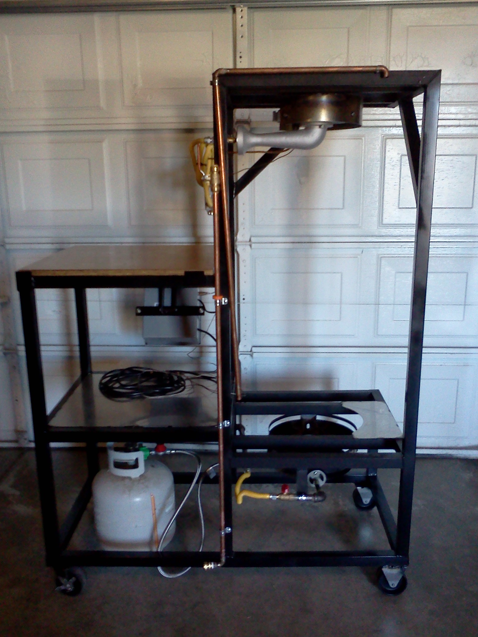
Here's my 20 gallon brew rig. I decided to build it for two reasons 1) I like beer; 2) I wanted to learn how to weld. It wasn't the first thing I built - a workbench, compressor stand, and welding cart came first - but it was my first real project.
The butcher block table in the first picture is a recent (and incomplete) addition. I use it as a prep table when brewing and the rig stores away underneath it when not in use.


The butcher block table in the first picture is a recent (and incomplete) addition. I use it as a prep table when brewing and the rig stores away underneath it when not in use.


Similar threads
- Replies
- 11
- Views
- 1K
- Replies
- 132
- Views
- 9K
- Replies
- 45
- Views
- 5K
