
goatchze
Well-Known Member
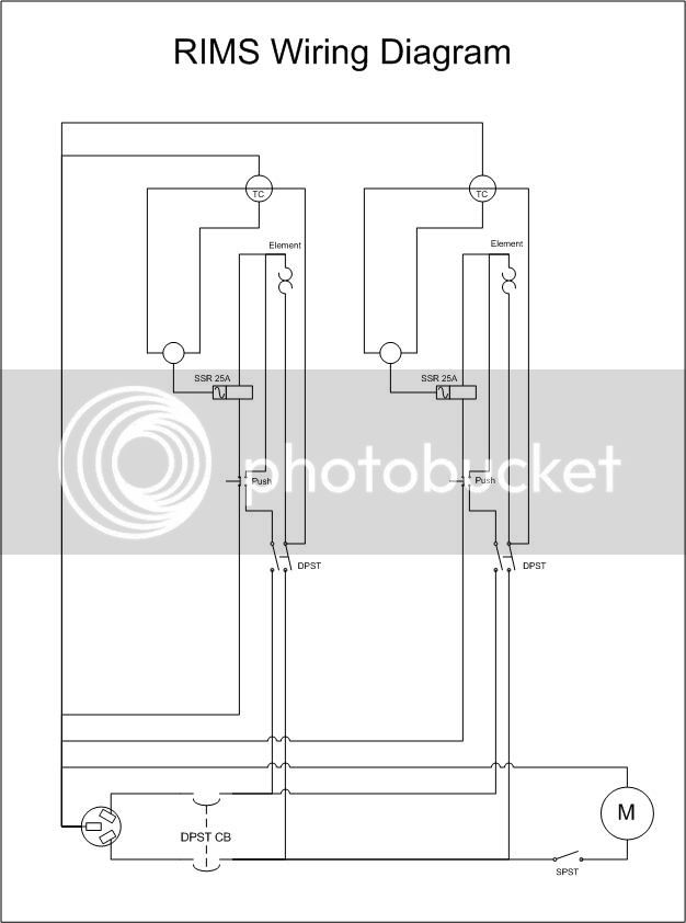
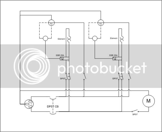
So I'm thinking of putting together the wiring for my RIMS system in the following way. One element will be my RIMS tube, the other my eKeggle.
The purpose is:
1. To be able to operate the two elements independently
2. To have the PID also work as my "ON" indicator. i.e. if the PID is on, the element is on
3. Be able to switch between 120/240V on the elements.
4. The PID conrtroller will only be used during 120V mode. i.e. during start up the temperature won't be close to the set point and I'll be running 240V manual. Then, when it gets close to the set point I'll flip to 120V and let the controller take over.
I'll have the 4th ground wire but the grounds aren't shown in the diagram.
Any advice? Comments? Experience?
P.S. I've also considered adding another relay on the RIMS tube so that it can only be on if the pump is on...

")


![Craft A Brew - Safale BE-256 Yeast - Fermentis - Belgian Ale Dry Yeast - For Belgian & Strong Ales - Ingredients for Home Brewing - Beer Making Supplies - [3 Pack]](https://m.media-amazon.com/images/I/51bcKEwQmWL._SL500_.jpg)


