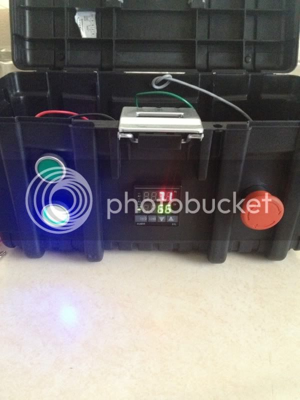
Hi all. I'm looking for some help wiring my basic basic RIMS tube cooler MLT. I believe I have all the correct parts but I'm looking for some opinions on how to wire up the system. Here is a list and pic of my parts:
Cooler MLT w/false bottom
SS Chugger pump w/SS ball valve
1.5" SS tri-clover RIMS tube
Camco 1500W 120v heating element
4" temp probe
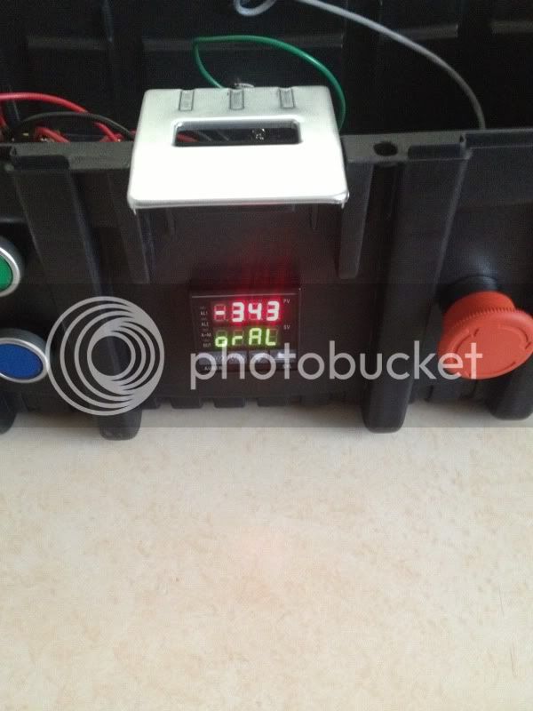
Auber 2352 PID
Auber 25A SSR
Heat sink to be mounted outside box
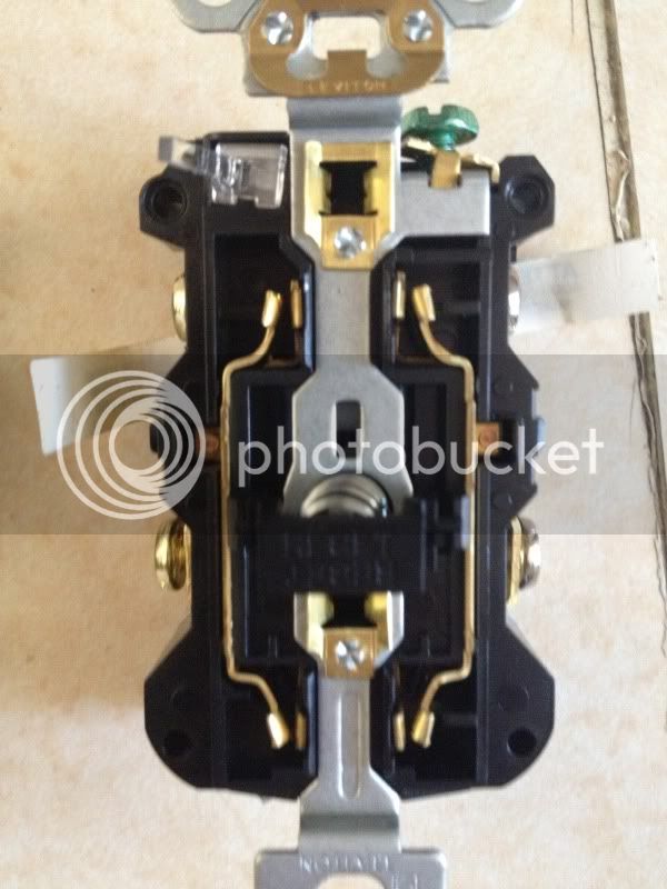
2 120V lighted switches (pump & element)
2 outlets for pump and element
1 LED indicator for element power
I plan on running the system off a standard 110 GFCI. Any direction/criticism will help. I'm just beginning. Thanks.
View attachment 170935


![Craft A Brew - Safale BE-256 Yeast - Fermentis - Belgian Ale Dry Yeast - For Belgian & Strong Ales - Ingredients for Home Brewing - Beer Making Supplies - [3 Pack]](https://m.media-amazon.com/images/I/51bcKEwQmWL._SL500_.jpg)


")